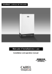
1
humiSet - Humidifier Programming Tool
User manual
INDEX
Introduction ...................................................................................................................................................... 3
Components ...................................................................................................................................................... 5
Installing the hardware ..................................................................................................................................... 7
Classifying the connections .............................................................................................................................. 8
Point 1 . On-board connections ...................................................................................................................... 13
Type A connection...................................................................................................................................... 13
Type B connection...................................................................................................................................... 14
Type C connection...................................................................................................................................... 15
Point 2. Off-board connections (“on the table”)............................................................................................. 16
Type D connection...................................................................................................................................... 16
Type E connection ...................................................................................................................................... 17
Type F connection ...................................................................................................................................... 18
Type G connection...................................................................................................................................... 19
Installing the Software.................................................................................................................................... 20
Changing the default serial port (COM1)....................................................................................................... 20
Using the software .......................................................................................................................................... 21
Programming with humiSet ........................................................................................................................ 21
Stopping humiSet............................................................................................................................................ 28
humiSet
Introduction
CAREL have developed a kit —humiSet— intended for both OEM customers and CAREL branches. It contains all
the HW & SW parts and components necessary to program any of CAREL controllers for any type of humidifier for
series humiSteam, heaterSteam, humiFog, gaSteam, kit OEM “KUE”.
With humiSet and a Personal Computer, the user can program (i.e. download the parameters needed to configure
the humidifier) both on-board and off-board (“on-the-table”) controllers.
HUMIDIFIER
CUSTOMER /
OEM /
CAREL SALES
OFFICES
humiSet
CONTROLLER
(“on the table”)
Figure 1
Cod. Carel +030220311 rel. 1.1 dated 27 August 2003
3
humiSet
Cod. Carel +030220311 rel. 1.1 dated 27 August 2003
4
humiSet
Components
-
Installation CD (Figure 2)
Figure 2
-
RS232-485 Converter (Figure 3)
Figure 3
-
230VAC (50/60Hz) / 12VAC transformer feeding the RS232-485 Converter (Figure 4)
Figure 4
-
RS232 Cable for connection between the PC serial port (output) and the RS232-485 Converter (Figure 5)
Figure 5
-
9 pin plug/ 25 pin female-terminal serial adapter for PC with 25 pin output (Figure 6)
Figure 6
Cod. Carel +030220311 rel. 1.1 dated 27 August 2003
5
humiSet
-
HPI (Humidifier Programming Interface) adapter (Figure 7)
Figure 7
Note: HPI must be powered only by the supplied transformer (figure 8) or by a transformer featuring an output 24
Vac protected against the short circuits.
-
230VAC (50/60Hz) / 24VAC transformer with (1x faston connector and 1x plug-in connector) for the HPI
adapter feeding “Boardcontroller” controllers (see below) (Figure 8)
Figure 8
-
3-to-4-pole communication cable with plug-in connectors for connection to RS232-RS485 Converter as an
HPI adapter, or directly to either the humidifier or “Boardcontroller” (Figure 9)
Figure 9
-
Flat communication cable for connection between the HPI & “Boardcontroller” (for type UM*******, UE***P****
& KUE******* humidifiers, see table 2) (Figure 10)
Figure 10
-
Flat cable for connection between the HPI & Humicontrol (Figure 11)
Figure 11
Cod. Carel +030220311 rel. 1.1 dated 27 August 2003
6
humiSet
Installing the hardware
CAREL supplies a complete hardware kit—humiSet—common to all controllers. The kit parts to be used for
configuring the controller will vary depending on the circumstances.
Figure 12 & Figure 13 show the standard kit installation, which is common in all cases.
PC
serial port
9-to-25pin adapter
(only for PC with 25-pin
serial port)
RS232-485
Converter
RS232 cable
3-to-4 pins cable
12 VAC
230 VAC
Figure 12
Figure 13
The hardware connections must be completed according to the circumstances, as described in detail in the following
paragraphs.
Cod. Carel +030220311 rel. 1.1 dated 27 August 2003
7
humiSet
Classifying the connections
We have already mentioned that it is possible to program both on-board controllers (i.e., controllers assembled in
finished humidifiers) and off-board controllers (i.e., controllers not connected to the humidifier, namely, put “on the
table”).
To help you to understand the different types of connections, it is worth referring to Figure 14, Figure 15, Figure 16,
and tables 1 & 2. They list the codes of the different controllers and Interface Boards that are used for the humidifiers,
and refer to the type of connection required for programming.
Table 1 refers to finished humidifiers and lists the codes of the different controllers and interface boards assembled in
the humidifiers.
Table 2 refers to controllers to configure “on the table”.
The letters in column “Type of Connection” indicate the classification of particular connections.
Interface
board
98C474C004
98C474C002
Interface
board
98C460C006
98C460C002
Interface
board
98C474C005
See Labels
at the bottom
Humicontrol
98C460C001 (URH*******, URS*******)
98C474C001 (UEH*******)
98C486C004 (UGH*******)
Humicontrol
98C460C003
(URC*******)
Humicontrol
98C493C001
(UAH*******)
Figure 14
Cod. Carel +030220311 rel. 1.1 dated 27 August 2003
8
humiSet
Boardcontroller
98C489C002
98C489C012
(UES*******)
Boardcontroller
98C489C003
98C489C013
(UMC*******)
Boardcontroller
98C489C001
98C489C011
(UEP*******)
Figure 15
Boardcontroller
CP1*******
Boardcontroller
CP4*******
Boardcontroller
CP2*******
Boardcontroller
CP3*******
Figure 16
Cod. Carel +030220311 rel. 1.1 dated 27 August 2003
9
humiSet
Table 1 - Finished humidifiers -
Type of connection
Type of Humidifier
Price-list Humidifier /
Controller codes
CAREL production
code
(on interface board
and controller labels)
Type of display
Int: 98C474C004 or
98C474C002
(serial output available)
Controll: 98C474C001
(Humicontrol)
With immersed
electrodes “humiSteam”
– humidity regulation
(rated production <= 15
kg/h)
Humidif: UE***H****
Controll: UEH*******
Int: 98C474C005
(serial output available)
Controll: 98C474C001
(Humicontrol)
With immersed
electrodes “humiSteam”
- humidity regulation
(rated production >= 25
kg/h)
A
(see
Figure 17
Figure 18
Figure 19)
With heaters
“heaterSteam” –
humidity regulation
Humidif: UR***H****
Controll: URH*******
With heaters
“heaterSteam” –
ON/OFF
Humidif: UR***C****
Controll: URC*******
With heaters
“heaterSteam” –
temperature regulation
(Turkish baths)
With atomisation
“humiFog”
With gas “gaSteam”
Immersed electrodes
“humiSteam” –
proportional-ON/OFF
regulation
(rated production <= 15
kg/h)
B
(see
Figure 20
Figure 21
Figure 22)
Humidif: UR***T****
Controll: URS*******
Humidif: UA***H****
Controll: UAH*******
Humidif: UG***H****
Controll: UGH*******
Cod. Carel +030220311 rel. 1.1 dated 27 August 2003
Int: 98C460C006 or
98C460C002
(serial output available)
Controll: 98C460C001
(Humicontrol)
Int: 98C460C006 or
98C460C002
(serial output available)
Controll: 98C460C003
(Humicontrol)
Humicontrol,
LED version
Int: 98C460C006 or
98C460C002
(serial output available)
Controll: 98C460C001
(Humicontrol)
Int: 98C460C006 or
98C460C002
(serial output available)
Controll: 98C493C001
(Humicontrol)
Humicontrol,
DIGIT version
Int: 98C460C006 or
98C460C002
(output available)
Controll: 98C486C004
(Humicontrol)
98C489C001 or
98C489C011
(Boardcontroller)
(serial output
unavailable)
Humidif: UE***P****
Controll: UEP*******
Immersed electrodes
“humiSteam” –
proportional-ON/OFF
regulation
(rated production >= 25
kg/h)
Immersed electrodes
“homeSteam”
Humicontrol,
DIGIT version
98C489C002 or
98C489C012
(Boardcontroller)
(serial output
unavailable)
Humidif: UM***C****
Controll: UMC*******
10
98C489C003 or
98C489C013
Boardcontroller)
(serial output
unavailable)
3-LED DISPLAY (red,
yellow & green)
humiSet
if without serial option
card TACP485000:
B
(see
Figure 20
Figure 21
Figure 22)
----------------------------------
Humidif: KUE*******
Immersed electrodes
OEM “KUE”
if with serial option card
TACP485000:
Controll: CP********
(Boardcontroller)
C
(see
Figure 23
Figure 24
Figure 25)
Cod. Carel +030220311 rel. 1.1 dated 27 August 2003
11
CP********
(Boardcontroller)
(output available if with
serial option card
TACP485000)
3-LED DISPLAY
(red, yellow & green)
humiSet
Table 2
- Controllers "on the table" Type of connection
Type of Humidifier
Price-list Humidifier /
Controller codes
With immersed
electrodes “humiSteam”
- humidity regulation
(rated production <= 15
kg/h)
With immersed
electrodes “humiSteam”
- humidity regulation
(rated production >= 25
kg/h)
CAREL production code
(on controller plate)
98C474C001
(Humicontrol)
Humidif: UE***H****
Controll: UEH*******
98C474C001
(Humicontrol)
Humidif: UR***H****
Controll: URH*******
98C460C001
(Humicontrol)
D
With heaters
“heaterSteam” –
humidity regulation
(see
Figure 26
Figure 27)
With heaters
“heaterSteam” –
ON/OFF
Humidif: UR***C****
Controll: URC*******
98C460C003
(Humicontrol)
With heaters
“heaterSteam” –
temperature regulation
(Turkish baths)
Humidif: UR***T****
Controll: URS*******
98C460C001
(Humicontrol)
With atomisation
“humiFog”
Humidif: UA***H****
Controll: UAH*******
98C493C001
(Humicontrol)
With gas “gaSteam”
Humidif: UG***H****
Controll: UGH*******
98C486C004
(Humicontrol)
Immersed electrodes
“humiSteam” –
proportional-ON/OFF
regulation
(rated production <= 15
kg/h)
Type of display
Humicontrol,
DIGIT version
Humicontrol,
LED version
Humicontrol,
DIGIT version
98C489C001 or
98C489C011
(Boardcontroller)
(output unavailable)
Humidif: UE***P****
Controll: UEP*******
E
(see Figure 28)
Immersed electrodes
“humiSteam” –
proportional-ON/OFF
regulation
(rated production >= 25
kg/h)
Immersed electrodes
“homeSteam”
98C489C002 or
98C489C012
(Boardcontroller)
(serial port unavailable)
Humidif: UM***C****
Controll: UMC*******
3-LED DISPLAY
(red, yellow & green)
98C489C003 or
98C489C013
Boardcontroller)
(serial port unavailable)
if without serial option
card TACP485000:
F
(see Figure 29)
--------------------------------if with serial option card
TACP485000:
Humidif: KUE*******
Immersed electrodes
OEM “KUE”
Controll: CP********
(Boardcontroller)
G
(see Figure 30)
Cod. Carel +030220311 rel. 1.1 dated 27 August 2003
12
CP********
(Boardcontroller)
(serial port available if
with serial option card
TACP485000)
3-LED DISPLAY (red,
yellow & green)
humiSet
Point 1 . On-board connections
Type A connection
After completing the standard installation (see Figure 13), connect the 3-to-4-pole cable to the Interface Board inside
the humidifier rack, as shown in Figure 17, Figure 18, and Figure 19.
Note: With this type of connection, the precondition to program the controller is that the humidifier must be "on".
RACK
3-to-4-pin cable
24 VDC
+
GND
Interface Board
Humicontrol
Figure 17
Figure 18
Figure 19
Precondition: since the board is installed on a finished humidifier, the controller programming can be performed only if
the humidifier is "on".
Cod. Carel +030220311 rel. 1.1 dated 27 August 2003
13
humiSet
Type B connection
The “Boardcontroller” controller used with this kind of connection has no serial port. Use the black 10-pin female
terminal in the middle of the board instead.
To make the connection, use the Humidifier Programming Interface (HPI, Figure 7) and the flat cable (Figure 10) for
connection between the HPI and the electronic board, as shown in Figure 20.
3-to-4-pin cable
RACK
Boardcontroller
Flat cable
HPI
Figure 20
Pay the utmost attention to the direction of insertion of the flat cable connector into the board: the HPI adapter might
fail if the direction is wrong. To avoid ambiguity, the flat communication cable is made so that, if the direction is wrong,
it can be easily noticed that the connector stroke is hampered by the electrolytic condenser near the black 10-pole
female terminal (see Figure 21 & Figure 22),
SIDE VIEW
right direction for
insertion of flat cable
electrolitic
capacitances
10 pins female
connector
Boardcontroller
Figure 21
Figure 22
Precondition: since the board is installed on a finished humidifier, the controller programming can be performed only if
the humidifier is "on".
Cod. Carel +030220311 rel. 1.1 dated 27 August 2003
14
humiSet
Type C connection
The “Boardcontroller” controller of the humidifiers requiring this kind of connection do not have any default serial port.
However, a small option card (code TACP485000) can be installed to allow serial connection by the green 3-pole
connector on the controller.
As with example A, plug the 3-to-4-pole connector in the “Boardcontroller” controller.
Unlike Interface Boards, in this case the output connector has 3 poles. Care must be taken when plugging the
3-to-4-pole cable connector (see Figure 23, Figure 24, and Figure 25).
RACK
Boardcontroller
+ - REF
3-to-4-pin cable
Figure 23
TACP485000
optional serial
card
INSERTED
Look at right
connector
position!
Figure 24
TACP485000
optional serial
card
INSERTED
Figure 25
Precondition: since the board is installed on a finished humidifier, the controller programming can be performed only if
the humidifier is "on".
Cod. Carel +030220311 rel. 1.1 dated 27 August 2003
15
humiSet
Point 2. Off-board connections (“on the table”)
In this case, the programming concerns controllers not electrically connected to the humidifier. As a result, a special
installation is required for connection to both the HPI and the 230VAC/24VAC transformer necessary to feed the
system.
Type D connection
Humicontrols can be programmed directly, without using the Interface board.
In this case, it is necessary to use the HPI (Figure 7), the 230VAC/24VAC transformer for HPI feeding (Figure 8), and
the flat cable for connection between the l’HPI and the controller “on the table” (Figure 10), as shown in Figure 26 and
Figure 27.
HPI
Flat cable
3-to-4-pin
cable
Faston
connections
Male and female
insertion connector
Humicontrol
230 VAC
24 VAC
Figure 26
Figure 27
Cod. Carel +030220311 rel. 1.1 dated 27 August 2003
16
humiSet
Type E connection
Any of “Boardcontroller” controllers can be programmed directly even if it is not connected to the humidifier.
In this case, you need:
• the HPI (Figure 7);
• the flat cable for connection between the HPI and Boardcontroller (Figure 10);
• the 230VAC/24VAC transformer (Figure 8) for feeding Boardcontroller controller in terminals G-G0 through
the faston connector (Figure 28). Note: in this case, the HPI does not need to be fed at 24VAC.
Precondition: the board can be programmed only if it is powered on.
G G0
Figure 28
Cod. Carel +030220311 rel. 1.1 dated 27 August 2003
17
humiSet
Type F connection
The “Boardcontroller” controller can be programmed directly even if it is not connected to the humidifier and the serial
option card TACP485000 is not installed.
In this case, you need:
• the HPI (Figure 7);
• the flat cable for connection between the HPI and Boardcontroller (Figure 10);
• the 230VAC/24VAC transformer (Figure 8) for feeding Boardcontroller controller in terminals G-G0 through
the plug-in connector (Figure 29). Note: in this case, the HPI does not need to be fed at 24VAC.
Precondition: the board can be programmed only if it is powered.
G G0
TACP485000
optional serial card
NOT INSERTED
Figure 29
Cod. Carel +030220311 rel. 1.1 dated 27 August 2003
18
humiSet
Type G connection
The “Boardcontroller” controller can be programmed directly even if it is not connected to the humidifier and the serial
option card TACP485000 is installed.
In this case, you need the 230VAC/24VAC transformer (Figure 8) for feeding “Boardcontroller” controller in terminals
G-G0 through the plug-in connector (Figure 30).
Precondition: the board can be programmed only if it is powered.
G G0
Look at right
connector position!
Please read
note below!
TACP485000
optional
serial card
INSERTED
Figure 30
Unlike Interface Boards, in this case the output connector has 3 poles. Care must be taken when plugging the
3-to-4-pole cable connector (see Figure 23 e Figure 24).
Cod. Carel +030220311 rel. 1.1 dated 27 August 2003
19
humiSet
Installing the Software
Please, refer to the “Readme.txt” file in the CD-ROM.
Changing the default serial port (COM1)
If a serial port other than default COM1 is required, proceed as described below (after installing the software).
Find folder Carel \ humiSet \ data \ nodes \ node0 from folder "Programs";
Identify file "driver.ini" and open it by using a text editor (e.g. NOTEPAD for Windows):
The text below will be displayed:
[config]
MaxRetry485=3
Line1=1,4,485
Line2=
Line3=
Line4=
Line5=
Line6=
The third line
Line1=1,4,485
contains the number identifying COM1 (figure 1 in bold).
To select COM2 you just have to modify the line as shown below:
Line1=2,4,485
Make sure you have not changed anything else, then click on exit to leave. You will be asked whether you want to
save the changes. Answer "yes". If humiSet was already active, it might be possible to go on using the system
without restarting it. Should problems occur, restart humiSet.
Cod. Carel +030220311 rel. 1.1 dated 27 August 2003
20
humiSet
Using the software
Programming with humiSet
The precondition for programming to start is prior connection of all hardware devices, as indicated in the previous
paragraphs.
Now the controllers can be programmed.
Once the installation of the software is completed, the icon below will be displayed.
•
Click twice on it to start running humiSet software.
A similar, smaller icon will be displayed in the bottom right-hand corner of the application bar:
Internet Explorer will be triggered, and the following home page will be displayed (Figure 31):
Figure 31
Press “OK”.
•
In case of trouble with any connection or with the feeding, the application will display the following error page
(Figure 32)
Figure 32
In this case, check both connections and feeding, then press “Retry”.
Cod. Carel +030220311 rel. 1.1 dated 27 August 2003
21
humiSet
•
If the communication is active, the following page will be displayed (Figure 33):
Figure 33
1-Draw the mouse on the first coloured bar “Controller/humidifier”, and press the left button of the mouse: a list of options will
be displayed. Here choose the controller category depending on the humidifier to which the controller is associated.
2-After making the first choice, select “Controller type”. Choose according to the type of controller installed on the
humidifier. Refer to tables 1 & 2, and to Figure 14, Figure 15 and Figure 16.
3-The third option concerns the rated production (kg/h of the humidifier where the controller must be installed).
4-The fourth option is about the Voltage of the humidifier where the controller must be installed, or its
constructive options.
5-The fifth option concerns the possible customised variations.
6-The sixth option is about possible controller versions required for particular humidifier versions. This option is
provided for future expansions; at present, there is no particular version.
The selection of the controller associated with the humidifier will be over when no menu asks “Please select:” any
more. Each message “Please select:” means an item that has not been selected yet.
The selection is organised in such a way that, once an option is selected, the following ones will give only options
consistent with the previously selected ones.
However, it is the operator's responsibility to check the consistency of the controller programming
selected and the type of humidifier where the controller must be installed. Be careful!
•
After selecting the last field, a Pop Up Window will display the code of the set of parameters to apply during the
programming. It is the same code that must be used to request the programmed spare controller. Press key OK
in the Pop Window (Figure 34). Then, the key “Ok” in the bottom left-hand corner will turn active. Press “Ok” to
continue. The system will check the consistency of the choices made with the controller firmware.
Figure 34
Cod. Carel +030220311 rel. 1.1 dated 27 August 2003
22
humiSet
•
If the consistency is confirmed, then a window indicating that everything is ready for parameter downloading will
be displayed (Figure 35):
Figure 35
•
If the consistency is not confirmed, then the option made does not suit the controller connected: for instance, a
humidifier like “humiSteam” type H is selected, and the firmware for the management of humidifier “KUE*******”
is stored, the following error page will be displayed (Figure 36):
Figure 36
Cod. Carel +030220311 rel. 1.1 dated 27 August 2003
23
humiSet
•
If humiSet does not contain the required set of parameters, the following error page will be displayed (Figure 37):
Figure 37
In this case,
-The connected controller might not suit the option selected; check controller and replace it with a suitable one;
refer to tables 1 & 2 and to Figure 14, Figure 15 and Figure 16; or:
-The firmware in the controller might be more recent than the database in humiSet; In this case, it is possible to
find the updated database for the new versions of the controller firmware in http://ksa.carel.com as shown in
the of Figure 33, or contact directly Carel. Anyway, we suggest checking carefully the previous points.
•
Conversely, if the communication between humiSet and the controller is broken, the following page will be
displayed (Figure 38):
Figure 38
Once page “Ready for the download” (Figure 35) is displayed, press “Download” to continue. Great attention
must be given to the fact that the controller must not be replaced while this page is displayed, either before or
after pressing Download. Otherwise, the programming might be affected by errors that are not detected by
humiSet. If the controller has to be replaced before pressing “Download”, you must necessarily press “Back to
‘Selection of the Controller’”.
Cod. Carel +030220311 rel. 1.1 dated 27 August 2003
24
humiSet
•
If the programming is performed correctly, the following page will be displayed (Figure 39):
Figure 39
Certain data for completion of the operations are provided for certain types of controllers. Check them for
correctness on the humidifier.
•
In case of trouble during the writing of certain parameters, the page below will be displayed (Figure 40):
Figure 40
If the trouble persists at the following attempt, then the controller might be faulty. Replace it as necessary.
Note: “Boardcontroller” controllers with firmware release 14 or earlier are not programmable while they are
showing the firmware release (at power-on, flashes of yellow and red led). Humicontrol controllers are not
programmable during the first 5 seconds from power-on (until “---“ is shown). If Figure 40, appears, retry only
after these events.
Cod. Carel +030220311 rel. 1.1 dated 27 August 2003
25
humiSet
•
Likewise, the following page might be displayed (Figure 41):
Figure 41
If the trouble persists at the following attempt, then the controller might be faulty. Replace it as necessary.
•
If, after completion of the programming, the page below is displayed, check connections and repeat the
programming (Figure 42):
Figure 42
Cod. Carel +030220311 rel. 1.1 dated 27 August 2003
26
humiSet
•
The following page might be displayed during utilization of humiSet (Figure 43):
Figure 43
Press “Retry” to continue.
So, the points above listed the steps to follow for programming the parameters of controllers. Now, they are ready and
can be used to manage the humidifier appropriately.
Cod. Carel +030220311 rel. 1.1 dated 27 August 2003
27
humiSet
Stopping humiSet
On completion of the controller programming, Internet Explorer can be exited.
However, it is worth noting that the icon below is still in the application bar:
As long as the icon is there, just trigger Internet Explorer and enter http://localhost + ENTER to restart humiSet.
When humiSet is exited, we suggest closing the icon as well. To do this, draw the pointer arrow on the icon in the
application bar
then:
-
Press the right button of the mouse
Select “Close”
Note: humiSet cannot remain active non-stop for more than 20 hours.
If this limit is exceeded, the page below might be displayed (Figure 44):
Figure 44
Just stop humiSet and start it up again.
Cod. Carel +030220311 rel. 1.1 dated 27 August 2003
28
CAREL S.p.A.
Via dell’Industria, 11 - 35020 Brugine - Padova (Italy)
Tel. (+39) 049.9716611 Fax (+39) 049.9716600
http://www.carel.com - e-mail: [email protected]
Cod. Carel +030220311
Rel. 1.1 dated 27 August 2003
Agency: