1
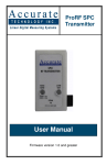
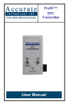
ProRF™
Wireless Encoder
Receiver/Transmitter
User Manual
WARRANTY
Accurate Technology, Inc., warrants this product against defective parts and
workmanship for 1 year commencing from the date of original purchase.
Upon notification of a defect, Accurate Technology, Inc., shall have the option
to repair or replace any defective part. Such services shall be the customer's
sole and exclusive remedy. Expenses incidental to repair, maintenance, or
replacement under warranty, including those for labor and material, shall be
borne by Accurate Technology, Inc. (including freight or transportation
charges during the first 30 days).
Except as expressly provided in this warranty, Accurate Technology, Inc.,
does not make any warranties with respect to the product, either expressed or
implied, including implied warranties of merchantability or fitness for a
particular purpose, except as expressly provided in this agreement.
Accurate Technology, Inc., shall not be liable for any special, incidental, or
consequential damages or for loss, damage or expense directly or indirectly
arising from the customer's use of or inability to use the equipment either
separately or in combination with other equipment, or for personal injury or
loss or destruction of other property, or from any other cause.
To request repair work (either warranty qualified parts or not), contact
Accurate Technology, Inc. directly by phone, fax, or e-mail. A Returned
Merchandise Authorization (RMA) number is required before returning a
product for repair.
This document is protected by the copyright laws of the United
States of America. No part of this document may be reproduced
by any means, electronic or otherwise, without the expressed
written permission of Accurate Technology, Inc.
© 2007 Accurate Technology, Inc.
MADE IN USA
ProRF Wireless Encoder Receiver/Transmitter
Page 2 of 20
FCC NOTICE
This equipment has been tested and found to comply with the limits for a
class B digital device, pursuant to part 15 of the FCC Rules. These limits are
designed to provide reasonable protection against harmful interference in a
residential installation. This equipment generates, uses and can radiate radio
frequency energy and if not installed and used in accordance with the
instructions, may cause harmful interference to radio communications.
However, there is no guarantee that interference will not occur in a particular
installation. If this equipment does cause harmful interference to radio or
television reception, which can be determined by turning the equipment off
and on, the user is encouraged to correct the interference by one or more of
the following measures:
•
Reorient or relocate the receiving antenna.
•
Increase the separation between the equipment and the receiver.
•
Connect the equipment to an outlet on a circuit different from that to
which the receiver is connected.
•
Consult the dealer or an experienced radio/television technician for
help.
Operation with non-approved equipment is likely to result in interference to
radio and TV reception.
The user is cautioned that changes and
modifications made to the equipment without the approval of the manufacturer
could void the user’s authority to operate this equipment.
FCC Identification
Contains FCC ID: OUR-XBEE
The enclosed device complies with Part 15 of the FCC rules. Operation is
subject to the following two conditions:
(i) This device may not cause harmful interference and
(ii) This device must accept any interference received, including
interference that may cause undesired operation.
ProRF Wireless Encoder Receiver/Transmitter
Page 3 of 20
Table of Contents
SECTION 1
GENERAL INFORMATION .............................................. 5
INTRODUCTION ........................................................................................ 5
SPECIFICATIONS ...................................................................................... 6
Encoder Transmitter ........................................................................... 6
DRO Receiver .................................................................................... 6
SECTION 2
CONFIGURATION ...................................................... 7
RECEIVER CONNECTIONS.......................................................................... 7
TRANSMITTER CONNECTION ...................................................................... 7
CHANNEL CONFIGURATION ........................................................................ 8
ASSOCIATING THE T RANSMITTER AND THE RECEIVER (LEARNING) ................... 9
TESTING................................................................................................10
ENCODER SENSITIVITY ............................................................................11
COMPLETING THE CONFIGURATION ............................................................12
SECTION 3
INSTALLATION.........................................................13
READOUT RECEIVER INSTALLATION ...........................................................13
ENCODER T RANSMITTER INSTALLATION ......................................................15
ENCODER T RANSMITTER INSTALLATION ......................................................16
SECTION 4
OPERATION ................................................................18
SECTION 4
OPERATION ................................................................19
OPERATION ...........................................................................................19
BATTERY INDICATION & REPLACEMENT ......................................................19
ProRF Wireless Encoder Receiver/Transmitter
Page 4 of 20
SECTION 1
GENERAL INFORMATION
Introduction
Thank you for purchasing the Accurate Technology, Inc. Wireless Encoder
Receiver/Transmitter system. These units are designed to be used as a wire
replacement system between a ProScaleTM Digital Readout (DRO) and a
Readhead Encoder.
Typical applications for the RF system include situations where it would be
difficult and/or expensive to route cabling between the DRO and the encoder.
Examples include:
•
Encoder cable lengths over 20 feet.
•
Installations where the encoder and DRO are located in separate
rooms and/or buildings.
•
Applications involving excessive motion of the encoder cabling.
•
Applications that would require the encoder cable being installed in
the same conduit/wire way with high voltage cables over long
distances (greater than 10 feet).
The RF system is easy to install and requires minimum maintenance. It is
backwards compatible with all previously manufactured ProScale
measurement products including all Incremental and Absolute encoders.
The system utilizes RF transceivers with the ability to provide two way
communications. This helps to guarantee the reliable transfer of position
information and provides remote annunciation of transmitter low battery
conditions and encoder status.
The RF system incorporates IEEE standard 802.15.4 radio modules operating
at 2.4GHz which yield reliable data communications with worldwide
acceptance. Typical operating range is from 50 to 100 feet (15 to 30 meters)
depending on environmental conditions.
Receiver power is derived from a 6 to 18 volt DC power supply and the
transmitter is powered from a single 3 volt lithium (123) battery. Average
battery life is from 3 to 6 months depending on usage.
NOTE: This RF system is designed for intermittent data transmission of
position information. Transmitter battery life is directly proportional to the
amount of data transmissions generated. Do not use this RF system in
applications where the ProScale linear measuring system is being used in
continuous operation.
ProRF Wireless Encoder Receiver/Transmitter
Page 5 of 20
Specifications
Encoder Transmitter
•
Enclosure: 2.94” L x 1.85” W x 1.4” H (75mm x 47mm x 36mm).
•
Power: One 3 volt lithium battery, Eveready EL123 or equivalent.
•
Current Consumption: 140uA standby, 45mA active.
•
Input: ProScale incremental, absolute or high speed encoder.
•
Indicators: Communications Error LED, Low Battery LED.
•
Average Battery Life: 3 to 6 months depending on service.
•
RF power output: 1 mW (0 dBm).
•
Frequency: 2.4 GHz ISM band using spread spectrum technology.
•
Typical RF range: 50 to 100 feet (15 to 30 meters) depending on
environmental conditions.
DRO Receiver
•
Enclosure: 2.94” L x 1.85” W x 1.4” H (75mm x 47mm x 36mm).
•
Power: 6 to 24 volts DC from a regulated and filtered power supply
(100-240VAC in – 15VDC out power supply included).
•
Current Consumption: 55 mA.
•
Output: DRO interface supporting Mitutoyo Digimatic SPC format.
•
Indicators: Message Received LED, Transmitter Low Battery.
•
RF sensitivity: -92 dBm.
•
Frequency: 2.4 GHz ISM band using spread spectrum technology.
NOTE: The actual range of the RF system is dependent on many
environmental factors. Please read through this manual BEFORE completing
the installation. If you are unsure of the range capabilities of the system for
your application, do not permanently mount the transmitter and receiver prior
to operational testing. This will allow easier relocation of either unit in the
event that the desired range is unattainable from the desired mounting
locations.
ProRF Wireless Encoder Receiver/Transmitter
Page 6 of 20
SECTION 2
CONFIGURATION
Receiver Connections
Connect the two position power plug to a power supply providing 6 to 24
VDC. . If using the provided plug-in power adapter, the wire with the white
stripe or trace is positive. Minimum current requirement is 100mA. The
terminals are identified by +24V and GND on the receiver top cover
label.
NOTE: The terminal strip plug is rotated 180 degrees when it is inserted into
the receiver. Be sure to verify the correct polarity PRIOR to applying power.
6 - 24 VDC
DRO
Ground
Turn on (or plug in) the power supply. Both LED indicators will illuminate for 1
second to indicate proper operation. Connect the supplied modular cable
between the Digital Readout and the receiver.
At this point, the DRO will display “no Enc”. This message may continue to
be displayed until the receiver and transmitter have been completely
configured.
Transmitter Connection
Connect the Readhead Encoder cable to the transmitter. Connections are
now complete.
Encoder
ProRF Wireless Encoder Receiver/Transmitter
Page 7 of 20
Channel Configuration
Prior to operation, the user can optionally set the RF communications channel
to a value other than the factory default (0). Unless there are other
ProScale Wireless Encoder systems in operation in the area, the factory
default channel setting can be used.
To access the channel selectors remove the enclosure screws located on
each side of the case from the Transmitter and the Receiver. Slide off the top
covers vertically from the bottom covers to expose the circuit boards and
selector switches.
To change the operating RF channel, use a small flat blade screwdriver and
rotate the channel selector until the desired channel number is indicated on
the switch.
When changing the RF channel number, BOTH receiver and transmitter
must be set to the same operating channel.
MUST BE SET TO THE SAME VALUE
ProRF Wireless Encoder Receiver/Transmitter
Page 8 of 20
Associating the Transmitter and the Receiver
(Learning)
NOTE: If you ordered this product as a complete system (not as
individual Receiver or Transmitter), the following procedure has been
completed for you at the factory and does not need to be repeated unless the new components are to be used with other Receivers or
Transmitters.
Receiver/Transmitter pairs purchased together and factory “Associated”
will have the same Serial Numbers followed by Rx and Tx. To change
the factory settings follow the instructions below.
On the receiver, open the jumper on JP2 by lifting it off the pins.
(JP2 is located next to the text: “OPEN FOR LEARN”.)
Momentarily press SW1 on the transmitter circuit board labeled LEARN.
If the association is successful, LED D3 COMM will illuminate briefly on the
transmitter. The position of the encoder can now be changed and the DRO
will reflect the position update.
Reinstall the jumper across both pins of JP2 on the receiver. This prevents
another encoder transmitter from being accidentally associated.
ProRF Wireless Encoder Receiver/Transmitter
Page 9 of 20
Testing
After a transmitter and receiver have been successfully associated, changing
the position of the encoder will be shown on the receiver’s attached DRO.
If a reliable RF communications link exists, the COMM ERROR LED (D3)
should not illuminate on the transmitter
but the MESSAGE LED (D3) should pulsate on the receiver whenever the
encoder position is changed.
If the COMM ERROR LED (D3) on the transmitter pulsates, it indicates that
one or more RF data messages are not being sent successfully to the
receiver. If this occurs more than once for every 50 messages, the location of
the transmitter and/or receiver may need to be changed.
ProRF Wireless Encoder Receiver/Transmitter
Page 10 of 20
Encoder Sensitivity
The transmitter is programmable for the amount of initial change in position
detected by the encoder before RF transmission occurs. This “window of
motion” allows for small amounts of motion, such as from machine vibration,
to be detected without frequently sending RF signals to the receiver. This
helps to increase transmitter battery life and minimizes RF communications.
Jumper JP2 on the transmitter, by default, is closed. In this mode, the
amount of position change detected from the last “resting” position must be at
least + .003” (.08mm). If JP2 is open (no jumper installed) the amount of
position change detected must be greater than + .009” (.23mm).
Once a position change greater than the programmed threshold has occurred,
all detectable motion changes will cause RF messages to be sent. After the
encoder stops detecting position changes for 5 seconds (2.5 seconds for a
high speed encoder), the transmitter then again engages the “window of
motion” tolerance.
If your application contains large amounts of vibration during normal
operation, consider using the larger motion tolerance to extend battery life.
Otherwise, the default jumper setting (closed) should be adequate.
ProRF Wireless Encoder Receiver/Transmitter
Page 11 of 20
Completing the Configuration
This product is supplied with Industrial strength Double Faced Tape to
facilitate easy installation/placement of the Transmitter and Receiver units. If
a more permanent installation is desired, proceed to
Section 3: Installation.
Otherwise the covers can be reinstalled. Be sure to orient the covers in the
same direction as they were removed and slide the top cover down over the
bottom cover until it is firmly in place. Install the two screws, one on each
side of the housing.
Your system is now ready for use.
ProRF Wireless Encoder Receiver/Transmitter
Page 12 of 20
SECTION 3
INSTALLATION
This product is supplied with Industrial strength Double Faced Tape to
facilitate easy installation/placement of the Transmitter and Receiver
units. If a more permanent installation is desired follow the instructions
in this section.
WARNING: Be sure to touch an electrically grounded object prior to
disassembly of system components to dissipate any static electric charge.
NOTE: These instructions pertain only to the installation of the Wireless
Encoder Receiver/Transmitter system. It assumes that the ProScale
Measuring System or other devices used with this product are already
installed. See the ProScale/Other manuals for installation of those respective
products.
Readout Receiver Installation
If the Receiver cover had not been removed prior to this step, remove the two
enclosure screws, one located on each side of the case. Slide off the top
cover vertically from the bottom cover to expose the circuit board. Unplug the
2 position power input terminal strip plug from the receiver module and set it
aside.
Gently push outward on the rear panel of the bottom enclosure, opposite the
modular connector, lifting the rear edge of the circuit board up and out. Set
the circuit board aside on a non-conductive surface.
ProRF Wireless Encoder Receiver/Transmitter
Page 13 of 20
Two mounting holes are located in the base of the bottom enclosure that
accept #6 (or M3) machine screws. Secure the bottom enclosure to a flat
vertical mounting surface. The mounting location chosen should be as
elevated as possible to provide the greatest RF signal range. The actual
mounting location will typically be limited by the length of the cable that
connects the Receiver to the Digital Readout.
Re-install the receiver board into the bottom enclosure by inserting the
modular connector end in first. Note the slot in both the front and back of the
housing to accept the circuit board. Gently push outward on the back of the
enclosure while fitting the circuit board into the slots. Be sure the modular
and power connectors are protruding completely through the enclosure wall.
Leave the top cover off of the receiver until configuration is complete.
ProRF Wireless Encoder Receiver/Transmitter
Page 14 of 20
Connect the two-position power plug to a power supply providing 6 to 24
VDC. . If using the provided plug-in power adapter, the wire with the white
stripe or trace is positive. Minimum current requirement is 100 mA. The
terminals are identified by +24V and GND on the receiver top cover
label.
NOTE: The terminal strip plug is rotated 180 degrees when it is inserted into
the receiver. Be sure to verify the correct polarity PRIOR to applying power.
6 - 24 VDC
DRO
Ground
Turn on (or plug in) the power supply. Both LED indicators will illuminate for 1
second to indicate proper operation. Connect the provided modular cable
between the Digital Readout and the receiver.
After all testing has been completed, the top cover can be reinstalled. Be
sure to orient the cover in the same direction as it was removed and slide the
top cover down over the bottom cover until it is firmly in place. Install the two
screws, one on each side of the housing.
ProRF Wireless Encoder Receiver/Transmitter
Page 15 of 20
Encoder Transmitter Installation
WARNING: Be sure to touch an electrically grounded object prior to
disassembly of system components to dissipate any static electric charge.
NOTE: These instructions pertain only to the installation of the Wireless
Encoder Receiver/Transmitter system. It assumes that the ProScale
Measuring System or other devices used with this product are already
installed. See the ProScale/Other manuals for installation of those respective
products.
If the Transmitter cover had not been removed prior to this step, remove the
two enclosure screws, one located on each side of the case. Slide off the top
cover vertically from the bottom cover to expose the circuit board. Unplug the
cable from the Encoder.
Gently push outward on the rear panel of the bottom enclosure, opposite the
modular connector, lifting the rear edge of the circuit board up and out. Set
the circuit board aside on a non-conductive surface.
ProRF Wireless Encoder Receiver/Transmitter
Page 16 of 20
Two mounting holes are located in the base of the bottom enclosure that
accepts #6 (or M3) machine screws. Secure the bottom enclosure to a flat
mounting surface. The mounting location should be as elevated as possible
to maximize RF signal range. This will typically be limited by encoder cable
length.
Due to regulations governing the transport of Lithium batteries your system
MAY or MAY NOT have the battery already installed. If the battery is not
installed, perform the following:
Remove the battery retaining ring on the transmitter circuit board by gently
lifting one end of the locking ring from the base of the battery holder. Insert
the lithium into the holder observing the correct polarity. A ‘+’ and ‘–’ symbol
are molded into the plastic holder. Improper battery installation will result in
no transmitter operation and excessive current drain from the battery. When
properly installed, the two LED indicators will momentarily illuminate for 1
second. Re-install the battery retainer ring by sliding it over the battery and
make sure the ends latch to the battery holder.
+
ProRF Wireless Encoder Receiver/Transmitter
-
Page 17 of 20
Re-install the transmitter board into the bottom enclosure by inserting the
modular connector end in first. Note the slot in both the front and back of the
housing to accept the circuit board. Gently push outward on the back of the
enclosure while fitting the circuit board into the slots. Be sure the modular
connector protrudes completely through the enclosure wall. Leave the top
cover off of the transmitter until configuration is complete.
(Shown without battery for clarity)
Connect the Readhead Encoder cable to the transmitter. Installation is now
complete.
Encoder
After all testing has been completed, the top cover can be installed. Be sure
to orient the cover in the same direction as it was removed and slide the top
cover down over the bottom cover until it is firmly in place. Install the two
screws, one on each side of the housing.
ProRF Wireless Encoder Receiver/Transmitter
Page 18 of 20
SECTION 4
OPERATION
Operation
The operation of the wireless encoder system is designed to be transparent to
the user. The ProScale system will operate just as it normally would if the
encoder cable were plugged directly into the DRO.
Battery Indication & Replacement
The transmitter monitors the status of the battery voltage whenever a
transmission occurs. When the battery starts to deplete to a low level of
operation, the transmitter will flash its LO BAT LED. In addition, a message is
sent to the receiver causing its TX LO BAT LED to flash. The user should
replace the transmitter battery as soon as possible. EL123 (or equivalent) 3volt lithium batteries can be found at most hardware or department stores.
Transmitter
Receiver
LOW BATTERY
Remove the battery retaining ring on the transmitter circuit board by gently
lifting one end of the locking ring from the base of the battery holder. Insert
the lithium battery into the holder observing the correct polarity. A ‘+’ and ‘-‘
symbol are molded into the plastic holder. Improper battery installation will
result in no transmitter operation and excessive current drain from the battery.
When properly installed, the two LED indicators will momentarily illuminate for
1 second. Re-install the battery retainer ring by sliding it over the battery and
make sure the ends latch to the battery holder.
+
ProRF Wireless Encoder Receiver/Transmitter
-
Page 19 of 20
Thank you for choosing a ProScale Product
MADE IN USA
Accurate Technology, Inc.
270 Rutledge Rd. Unit E
Fletcher, NC 28732 USA
800 233-0580 • 828-654-7920
Fax 828-654-8824
www.proscale.com
[email protected]
This manual is available at www.proscale.com
Please return your Product Registration Card
or register your system at:
www.proscale.com/registration.htm
P/N 800-1206-001, Revision A, Copyright ©, 2007 Accurate
Technology, Inc. All rights reserved.
ProRF Wireless Encoder Receiver/Transmitter
Page 20 of 20