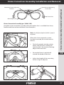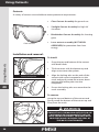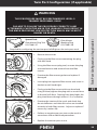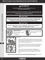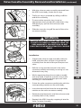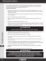
1
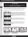
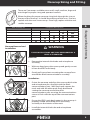
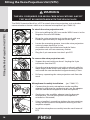
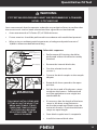
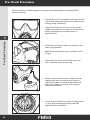
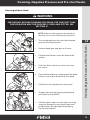
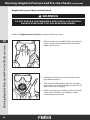
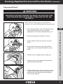
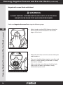
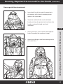
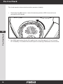
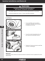
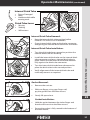
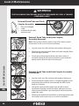
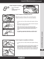
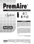
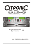
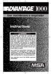
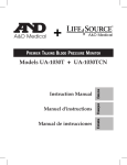
USER MANUAL
Information contained in this manual is technically accurate at the time of this
printing. Updates are made periodically to the information herein.
If you have comments please forward them to Avon Protection Systems, Inc..
THANK YOU
Multi-language versions of this manual available at www.avon-protection.com.
AVON FM53
Part number: 72601/59
Issue 2.0
JAN 2010
Table of Contents
Section
Page
1
Introduction
2
2
FM53 Air Purifying Respirator
3
3
NIOSH Cautions and Limitations
4
4
General Warnings
7
5
Sizing and Fitting Procedures
8
6
Nosecup Sizing and Fitting
9
7
Fitting the Voice Projection Unit (VPU)
10
8
Quantitative Fit Test
11
9
Pre-Check Procedure
12
10
Donning, Negative Pressure and Pre-Use Checks
13
11
Pre-Use Check
18
12
Doffing the Mask (removing)
19
13
Canister Installation and Removal
20
14
Storage and Transportation
21
15
Deployment Stowage
22
16
Head Harness Removal and Installation
23
17
Protective Hood Installation and Removal
24
18
Using the Hydration System
25
19
Vision Correction Assembly Installation and Removal
27
20
Using Outserts
28
21
Twin Port Configuration (if applicable)
29
22
Valve Cassette Assembly Removal and Installation
30
23
Cleaning Procedures
32
24
Maintenance Allocation
33
25
Operator Maintenance
34
26
Level-2 Maintenance
38
27
Operator Troubleshooting Procedures
40
28
Level-2 Maintenance Troubleshooting
42
29
Spare Parts Overview
49
1
2
3
4
5
6
7
8
9
10
11
12
13
14
15
16
17
18
19
20
21
22
23
24
25
26
27
28
29
Introduction
Introduction
1
2
3
4
5
6
7
8
9
10
11
12
13
14
15
16
17
18
19
20
21
22
23
24
25
26
27
28
29
2
Congratulations on receiving the most advanced Air Purifying Respirator (APR) in
the world. When used in accordance with these instructions, the FM53 Protective
Mask will provide the operator with the maximum level of protection, to the face,
eyes and respiratory tract from Chemical, Biological, Radiological and Nuclear
(CBRN), riot control agents and certain Toxic Industrial Chemicals (TICs).
The FM53 is NIOSH approved for use in specific configurations only.
These user instructions are arranged into three sections:
Section 1: NIOSH APR configurations
Section 3: Level I operator and Level II maintenance tasks.
There are separate User Instructions for FM53 used with the Avon ISI ST53 SCBA
FM53 Air Purifying Respirator
The FM53 Protective Mask is also available in a Twinport configuration that allows the
canister to be installed on either the left or right (not both) side of the mask.
The mask incorporates interchangeable nosecups in 5 sizes:
XS
extra-small
S
small
M
medium
L
large
XL
extra-small
The major features of the mask are:
• The butyl & silicon rubber blended faceblank.
This provides an effective seal with increased comfort
• optical quality eyelens
• Electronic Communications Port (ECP)
• Variable Resistance Exhalation Unit (VREU ).
The FM53 APR makes use of a Variable Resistance Exhale Unit (VREU). This contains
the Exhale Valve Cassette Assembly which allows the mask the operational flexibility
to be used in APR (NP Negative Pressure) or SCBA (Positive Pressure) modes . This
manual refers to instruction for use of the FM53 in the negative pressure APR mode
only.
WARNING
SPECIAL CARE MUST BE TAKEN TO ENSURE THAT THE VALVE
CASSETTE ASSEMBLY WITHIN THE VREU IS SET TO THE CORRECT
POSITION FOR THE INTENDED APPLICATION. INCORRECT
SETTING WILL VOID THE NIOSH APPROVAL .
1
2
3
4
5
6
7
8
9
10
11
12
13
14
15
16
17
18
19
20
21
22
23
24
25
26
27
28
29
FM53 Air Purifying Respirator
The FM53 Protective Mask is available in four sizes with either a left or right filter mount,
marked with letters as listed; Extra Small (XS), Small (S), Medium (M), or Large (L).
3
NIOSH Cautions and Limitations
NIOSH Cautions and Limitations
1
2
3
4
5
6
7
8
9
10
11
12
13
14
15
16
17
18
19
20
21
22
23
24
25
26
27
28
29
4
S - Special or Critical User’s Instructions
When FM53 is used as an APR the VREU Lever must be fully rotated counter-clockwise
to the vertical APR position .
The FM53 must be stored in the approved Storage Bag and liner except when in
operational use or maintained. The Canister must remain sealed until fitted to the
respirator prior to use.
The Voice Projection Unit (VPU) is a required component for the NIOSH CBRN
approved configuration.
Industrial APR Cautions and Limitations for Use
A
Not for use in atmospheres containing less than 19.5 percent oxygen.
B
Not for use in atmospheres immediately dangerous to life or health.
C
Do not exceed maximum use concentrations established by regulatory standards
.
H
Follow established cartridge and canister change schedules or observe ESLI to
ensure that cartridges and canisters are replaced before breakthrough occurs.
J
Failure to properly use and maintain this product could result in injury or death.
L
Follow the manufacturer’s User’s Instructions for changing canisters.
M
All approved respirators shall be selected, fitted, used, and maintained in
accordance with MSHA, OSHA, and other applicable regulations.
N
Never substitute, modify, add, or omit parts. Use only exact replacement parts in
the configuration as specified by the manufacturer.
O
Refer to User’s Instructions and/or maintenance manuals for information on use
and maintenance of these respirators.
P
NIOSH does not evaluate respirators for use as surgical masks.
NIOSH Cautions and Limitations (continued)
Special or critical User’s instructions and/or specific limitations apply. Refer to
User’s instructions before donning.
BB
Not for use for entry into atmospheres immediately dangerous to life or health.
CC
For entry, do not exceed maximum use concentrations established by regulatory
standards.
FF
Respirators to be fit tested prior to use with heaviest cartridges, canisters, filters
and/or accessories intended to be used. Fit testing should also be conducted
while wearing all personal protective equipment intended to be used. See user’s
instructions for fit test requirements .
CBRN APR Cautions and Limitations for Use
A
Not for use in atmospheres containing less than 19.5 percent oxygen.
B
Not for use in atmospheres immediately dangerous to life or health.
C
Do not exceed maximum use concentrations established by regulatory
standards.
H
Follow established cartridge and canister schedules or observe ESLI to ensure
that cartridges and canisters are replaced before breakthrough occurs.
I
Contains electrical parts that may cause an ignition in flammable or explosive
atmospheres .
J
Failure to properly use and maintain this product could result in injury or
death.
L
Follow the manufacturer’s User’s Instructions for changing canisters.
M
All approved respirators shall be selected, fitted, used, and maintained in
accordance with MSHA, OSHA, and other applicable regulations.
N
Never substitute, modify, add or omit parts. Use only exact replacement parts
in the configuration as specified by the manufacturer.
O
Refer to User’s Instructions and/or maintenance manuals for information on
use and maintenance of these respirators.
P
NIOSH does not evaluate respirators for use as surgical masks .
R
Some CBRN agents may not present immediate effects from exposure, but
can result in delayed impairment, illness, or death.
S
Special or critical User’s Instructions and/or specific use limitations apply.
Refer to User’s Instructions before donning.
T
Direct contact with CBRN agents requires proper handling of the respirator
after each use and between multiple entries during the same use.
Decontamination and disposal procedures must be followed. If contaminated
with liquid chemical warfare agents, dispose of the respirator after
decontamination.
V
Not for use in atmospheres immediately dangerous to life and health or
where hazards have not been fully characterized.
NIOSH Cautions and Limitations (continued)
S
1
2
3
4
5
6
7
8
9
10
11
12
13
14
15
16
17
18
19
20
21
22
23
24
25
26
27
28
29
5
NIOSH Cautions and Limitations (continued)
NIOSH Cautions and Limitations (continued)
1
2
3
4
5
6
7
8
9
10
11
12
13
14
15
16
17
18
19
20
21
22
23
24
25
26
27
28
29
6
W
Use replacement parts in the configuration as specified by the applicable
regulations and guidance.
X
Consult manufacturer’s User’s Instructions for information on the use, storage,
and maintenance of these respirators at various temperatures.
Y
This respirator provides respiratory protection against inhalation of
radiological and nuclear dust particles. Procedures for monitoring radiation
exposure and full radiation protection must be followed.
Z
If during use an unexpected hazard is encountered such as a secondary CBRN
device, pockets of entrapped hazard or any unforeseen hazard, immediately
leave the area for clean air.
CC
For entry, do not exceed maximum use concentrations established by
regulatory standards.
HH
When used at defined occupational exposure limits, the rated service time
cannot be exceeded. Follow established canister change out schedules.
QQ
Use in conjunction with personal protective ensembles that provide
appropriate levels of protection against dermal hazard. Failure to do so may
result in personal injury even when the respirator is properly fitted, used, and
maintained.
UU
The respirator should not be used beyond eight (8) hours after initial
exposure to chemical warfare agents to avoid possibility of agent permeation.
If liquid exposure is encountered, the respirator should not be used for more
than two (2) hours.
General Warnings
FAILURE TO OBSERVE THESE WARNINGS
MAY RESULT IN INJURY OR DEATH!
•
Only CBRNF12B and CTF12 Canisters are NIOSH approved for use with FM53.
•
The operator must read and fully understand these operator instructions prior to
use.
•
The operator must have received training in the use of the mask including, but
not limited to, pre-use check, donning, seal check, use, doffing (removal), modes
of operations and maintenance.
•
Sizing and fitting procedures must be performed by a trained (Level-2)
technician. Operator safety depends on a properly fitted mask. The mask must be
sized and adjusted for the individual operator following the procedures given in
these instructions. Injury or death can occur if the mask does not properly fit.
•
It is important to conduct proper care, maintenance and keep the mask clean. An
improperly maintained mask may compromise its ability to provide maximum
protection.
•
The mask used in APR mode is not intended for use in enclosed or confined
space or oxygen deficient environment.
•
Do not over-tighten the Canister. Canister should be hand tight.
•
Always select the correct size of mask for each individual operator. Operators are
required to conduct a quantitative fit test to confirm the correct mask size has
been selected.
•
Always don and doff the mask in an area known to be free of contaminants.
•
Always perform a satisfactory negative pressure check before entering a
contaminated area.
•
Keep a cleanly shaven face to ensure a good seal. Operators shall remove all
hairpins, combs, hair knots, buns, or braids that will interfere with the seal of the
mask.
•
Do not use abrasive or solvent cleaners of any sort to clean the mask.
•
Do not wear contact lenses when wearing the mask.
•
Specialist maintenance, other than the normal operator checks (Level 1) specified
in this manual, must be performed by an Avon certified service center or by Avon
certified (Level-2) technician.
General Warnings
WARNING
1
2
3
4
5
6
7
8
9
10
11
12
13
14
15
16
17
18
19
20
21
22
23
24
25
26
27
28
29
7
Sizing and Fitting Procedures
Sizing and Fitting Procedures
1
2
WARNING
3
SIZING AND FITTING PROCEDURES MUST BE PERFORMED BY A
4
TRAINED (LEVEL-2) TECHNICIAN
5
The FM53 Protective Mask is available in four sizes. A sizing tool is available to assist in
6
initial selection of the correct mask size. It does no more than assist initial selection.
Only a successful completion of a quantitative fit test can determine correct fit.
7
It is a requirement that the initial sizing and fitting be performed by trained
8
personnel.
9 Correct
When sizing is correct the eyes of the operator appear
10
on or slightly above the lens horizontal centre line. A
correctly sized mask should make firm contact with
11
the face around the entire length of the face seal. The
distance between the edge of the mask and the ear
12 Correct
should be typically in the range .5 to 1.5 inches (15mm
correct
to 25mm).
13
14
If the mask is too small, the operator may lose seal
performance and protection. The mask will be
15
Correct
uncomfortable to wear and could affect field of view.
16 Too Smalltoo small
17
If the mask is too large the operator may lose seal
18
performance and protection. The operator will also
Too Small
experience a very loose fit with subsequent mask
19
slippage.
20
too large
21
Sizing Tool (pn:72601/55)
22
offers a sizing tool to aid in the selection of the correct mask size.
TooAvon
Large
Too
Small
23
24
25 Too Large
26
Place the tool to the face
Read off the appropriate
Check eye location.
27
diagonally along a line
size. If on or near the
from the point of the
boundary between two
28
chin to the widest point
sizes, select the larger size.
of the cheekbone.
29
8
Too Large
Nosecup Sizing and Fitting
When checking for proper nosecup sizing look through the visor at
the top of the nosecup. It should be at the top of the nose. If to low,
replace with the next size nosecup. If too high, replace with the next
smaller nosecup.
Compatible Nosecup Sizes
Mask Assembly Size
Extra Small
Small
Medium
Large
Extra Large
Large
Medium
Small
Extra Small
Nosecup Removal and
Installation:
WARNING
THESE INSTRUCTIONS ARE TO BE PERFORMED BY A
LEVEL-2 TECHNICIAN
Removal:
• Remove the internal drink tube and microphone
assembly.
• With one hand grasp the nosecup and gently unseat
it from the VREU main body.
• Gently pull up and out unseating the nosecup from
around the drink/communications assembly.
Installation:
• Orient the nosecup and align the nosecup drink tube
and microphone pass-through with the drink
communications port. With one hand support the
mask and with the other push firmly downward
seating the nosecup around the drink
communications port ensuring the communications
cutout is flush with the top of the communications
port.
• Ensure the VREU main body cutout in the nosecup is
properly routed around the VREU main body
assembly on the interior of the mask.
• Install the internal drink tube and microphone
assemblies.
1
2
3
4
5
6
7
8
9
10
11
12
13
14
15
16
17
18
19
20
21
22
23
24
25
26
27
28
29
Nosecup Sizing and fitting
There are 5 nosecups available extra small, small, medium, large and
extra large for proper sizing and operator comfort.
9
Fitting the Voice Projection Unit (VPU)
FItting the Voice Projection Unit (VPU)
1
2
3
4
5
6
7
8
9
10
11
12
13
14
15
16
17
18
19
20
21
22
23
24
25
26
27
28
29
10
WARNING
THE VPU IS REQUIRED FOR NIOSH CBRN APLLICATIONS. ANY FIT
TEST MUST BE UNDERTAKEN WITH THE VPU IN PLACE.
The FM53 Protective Mask has a ECP to attach the voice projection unit and other
communications devices which use an internal microphone. (pn: 72601/13)
To attach the voice projection unit:
• Prior to installing the VPU, ensure the VREU Lever is in the
Negative Pressure APR Mode.
• Bring the voice projection unit to the mask with one
hand at approximately 45 degrees to the right.
• Locate the mounting groove ,insert the voice projection
unit and rotate clockwise ¼ turn.
An audible click should be heard and the Voice
projection unit will not rotate any further.
• Plug the 3-pin connecter into the 3-pin ECP.
To remove the voice projection unit:
• Support the mask with one hand. Unplug the 3-pin
connector from the ECP.
• Grasp the voice projection unit with one hand; with the
index finger of the same hand, depress the locking lever
and rotate the counterclockwise approximately ¼ turn.
• Pull away separating the voice projection unit from the
mask.
Microphone Assembly Installation
(pn: 72601/17)
• Connect the dynamic microphone to the amplifier
adapter by aligning the connecting pins on the adapter
with the connector receptacle on the microphone.
• Gently press the amplifier adapter into the dynamic
microphone. (Ensure the dynamic microphone is
oriented as illustrated)
• Using a jeweller’s screwdriver, tighten the two retaining
screws on the dynamic microphone securing it to the
amplifier adapter.
• Install the microphone assembly into the mask internal
ECP.
Quantitative Fit Test
FIT TESTING PROCEDURES MUST BE PERFORMED BY A TRAINED
(LEVEL-2) TECHNICIAN!
Avon recommends that the operator undertake a quantitative fit test to confirm that
the correct mask size has been selected and that a good fit can be obtained.
• Avon recommends a Fit Factor (FF) of 2500 minimum.
• Fit test exercises should be performed in accordance with established protocol.
• When using an ambient particle type tester, a background particle count of
10,000 is recommended before testing.
Skullcap
Brow Strap Cover
Brow Strap
Temple Strap
Cheek Strap
Follow this sequence:
• Performance of fit testing should be
performed without the hood assembly
attached.
• Remove the internal drink tube.
• Don the selected mask size
(section 7).
• Connect the drink coupler to the sample
adapter.
• Rotate drink lever upward to the open
position.
WARNING
FOLLOWING INITIAL SIZING AND
FITTING DO NOT READJUST THE
BROW AND TEMPLE STRAPS.
CHEEK AND TEMPLE STRAPS
TIGHTNESS MAY REQUIRE
ADJUSTING EVERY TIME THE
MASK IS DONNED.
• Pull the loose end of the harness straps
to tighten the harness. Sufficient load
must be applied to ensure a tight but
comfortable fit.
• If necessary alter the length of the brow
straps in the brow strap pockets to
ensure the temple and cheek straps do
not touch the ears. Check that the brow
straps are equal length.
• Stow drink coupler into it’s receptacle.
• Install the internal drink tube.
Quantitative Fit Test
WARNING
1
2
3
4
5
6
7
8
9
10
11
12
13
14
15
16
17
18
19
20
21
22
23
24
25
26
27
28
29
11
Pre-Check Procedure
Pre-Check Procedure
1
2
3
4
5
6
7
8
9
10
11
12
13
14
15
16
17
18
19
20
21
22
23
24
25
26
27
28
29
12
Always perform the following pre-use check procedure before using the FM53
Protective Mask:
• Ensure the mask is complete and is the correct
size for the particular operator as determined
during sizing and fitting.
• Check that there are no cuts or tears in the
rubber components, no chips or cracks in the
plastic components and the eyelens is
optically clear.
• Check that the brow straps are stowed in the
brow strap pockets.
Note: Brow and temple straps should be equal
length.
8
• Check that the lower two cheek straps are
fully slackened prior to donning.
• Always check that the mask is fitted with an
appropriate canister and ensure that the
canister has been correctly attached (hand
tight only). Refer to section 13 for proper
canister installation.
• Check that the Valve Cassette Assembly Lever
is set to the vertical position for the APR
Negative Pressure Mode.
Donning, Negative Pressure and Pre-Use Checks
WARNING
IMPORTANT: BEFORE DONNING THE MASK FOR THE FIRST TIME
THE OPERATOR MUST BE PROPERLY SIZED AND FITTED. SEE
SECTION 5!
NOTE: Mask must be properly stowed prior to
donning. See section 8 for proper procedures.
• The voice projection unit must be removed
prior to donning the mask.
• Remove head gear and glasses if worn.
• Pull the head harness over the front of the
eyelens.
• Pull hair back and insert the chin into
the mask.
• Grasp the head harness tab and pull the head
harness over and to the back of your head.
• Pull the harness tightly down at the rear.
• Support the mask by locating and placing
your hand over the VREU.
• Pull the cheek straps one at a time, ensuring
straps lay flat against your head. Brow and
temple straps are adjusted during fitting.
Do not over-tighten.
1
2
3
4
5
6
7
8
9
10
11
12
13
14
15
16
17
18
19
20
21
22
23
24
25
26
27
28
29
Donning, Negative Pressure and Pre-Use Checks
Donning without Hood
13
Donning, Negative Pressure and Pre-Use Checks (continued)
Donning, Negative Pressure and Pre-Use Checks (continued)
1
2
3
4
5
6
7
8
9
10
11
12
13
14
15
16
17
18
19
20
21
22
23
24
25
26
27
28
29
14
Negative Pressure Check without Hood
WARNING
DO NOT ENTER A CONTAMINATED AREA UNTIL A SUCCESSFUL
NEGATIVE PRESSURE TEST HAS BEEN PERFORMED!
Perform a Negative Pressure Test using the following steps
• With a hand over the VREU, blow out hard to
force out any contaminated air around the
edges of the mask.
• With palm of hand, cover the canister inlet
port and breathe in.
• The mask should collapse against your face
and remain so while holding your breath. If it
does, the mask is airtight.
• If the mask does not collapse, check for leaks.
If the mask still does not collapse, notify
maintenance personnel.
Donning, Negative Pressure and Pre-Use Checks (continued)
WARNING
IMPORTANT: BEFORE DONNING THE MASK FOR THE FIRST TIME
THE OPERATOR MUST BE PROPERLY SIZED AND FITTED. SEE
SECTION 5!
NOTE: Mask must be properly stowed prior to
donning. See section 8 for proper stowing procedure.
• The voice projection unit must be removed
prior to donning the mask. For CBRN
applications it must be refitted before use.
• Remove head gear and glasses if worn.
• Pull hair back and insert the chin into the
mask.
• Grasp the head harness tab and pull the
head harness over and to the back of your
head.
• Pull the harness tightly down at the rear.
• Support the mask by locating and placing
your hand over the VREU.
• Pull the cheek straps one at a time, ensuring
straps lay flat against your head. Brow and
temple straps are adjusted during fitting.
Do not over-tighten.
1
2
3
4
5
6
7
8
9
10
11
12
13
14
15
16
17
18
19
20
21
22
23
24
25
26
27
28
29
Donning, Negative Pressure and Pre-Use Checks (continued)
Donning with Hood
15
Donning, Negative Pressure and Pre-Use Checks (continued)
Donning, Negative Pressure and Pre-Use Checks (continued)
1
2
3
4
5
6
7
8
9
10
11
12
13
14
15
16
17
18
19
20
21
22
23
24
25
26
27
28
29
16
Negative Pressure Check with Hood
WARNING
DO NOT ENTER A CONTAMINATED AREA UNTIL A SUCCESSFUL
NEGATIVE PRESSURE TEST HAS BEEN PERFORMED!
Perform a Negative Pressure Test using the following steps
• With a hand over the VREU, blow out hard to
force out any contaminated air around the
edges of the mask.
Protective Hood removed for clarity
• With palm of hand, cover the canister inlet port
and breathe in.
• The mask should collapse against your face and
remain so while holding your breath. If it does,
the mask is airtight.
• If the mask does not collapse, check for leaks.
If the mask still does not collapse, notify
maintenance personnel.
Protective Hood removed for clarity
Donning, Negative Pressure and Pre-Use Checks (continued)
• Insert both hands through the opening in
the bottom of the hood spreading them
apart as far as possible.
• Trace the outline of the mask with both
hands pushing the protective hood over the
head, covering the head, neck and
shoulders.
• Insert your arms, one at a time, through the
holes formed by the underarm straps.
• Adjust by pulling on the free running end at
the same time.
1
2
3
4
5
6
7
8
9
10
11
12
13
14
15
16
17
18
19
20
21
22
23
24
25
26
27
28
29
Donning, Negative Pressure and Pre-Use Checks (continued)
Donning with Hood continued
17
Pre-Use Check
Pre-Use Check
1
2
3
4
5
6
7
8
9
10
11
12
13
14
15
16
17
18
19
20
21
22
23
24
25
26
27
28
29
18
This check needs to be carried out with a partner or buddy.
• Check that the VREU Lever is set to the correct position. VREU Lever to be set
vertically for APR Mode.
• For CBRN applications fit the VPU and ensure a new Energizer EL123 or Duracell
DL123 battery is installed into the VPU prior to entering a hazardous environment.
Doffing the Mask (removing)
• When the protective hood is attached, release underarm strap fasteners, grasp
the bottom of the protective hood and pull the hood up and over the head.
with hood
without hood
• Slacken the cheek straps to their fullest extent.
with hood
without hood
• Grasp the front of the mask and pull the mask well forward and lift upwards then
backwards off the head.
1
2
3
4
5
6
7
8
9
10
11
12
13
14
15
16
17
18
19
20
21
22
23
24
25
26
27
28
29
Doffing the Mask (removing)
Doffing the Mask (removing)
19
Canister Installation and Removal
WARNING
FAILURE TO OBSERVE THESE WARNINGS
MAY RESULT IN INJURY OR DEATH!
•
Only CBRNF12B and CTF12 Canisters are NIOSH approved for use with FM53.
•
Do not over-tighten the Canister. Canister should be hand tight.
Installation:
• Ensure the filter mount gasket is
attached to the filter mount before
installing the Canister.
Canister Installation and Removal
1
2
3
4
5
6
7
8
9
10
11
12
13
14
15
16
17
18
19
20
21
22
23
24
25
26
27
28
29
20
• Insert the male threaded portion of
the Canister into the filter mount.
• Rotate the Canister clockwise until the
Canister is hand tight.
Removal:
Grasp the Canister and turn it counter clockwise until the Canister separates from the
filter mount.
Storage and Transportation
FAILURE TO PROPERLY STORE YOUR MASK COULD RESULT IN THE
MASK NOT PROVIDING ADEQUATE PROTECTION WHEN USED
NEXT!
Faceform (pn: 72601/53)
The faceform is used to prevent damage to the
mask in storage. It is used for storage periods
in excess of 30 days.
Safe storage and transportation of the mask is vitally important in maintaining
its effectiveness:
• Store the mask in the NIOSH approved Storage Bag and Liner.
• Store and transport in a clean and dry environment within the guidelines of
local established procedures.
• Do not store or transport the mask under heavy or sharp objects.
• Do not store or transport the mask where it could be exposed to extremes of
temperatures or direct sunlight.
• Always clean and thoroughly dry the mask before storage.
Storage and Transportation
WARNING
1
2
3
4
5
6
7
8
9
10
11
12
13
14
15
16
17
18
19
20
21
22
23
24
25
26
27
28
29
21
Deployment Stowage
Deployment Stowage
1
2
3
4
5
6
7
8
9
10
11
12
13
14
15
16
17
18
19
20
21
22
23
24
25
26
27
28
29
22
Avon provides a number of carriers for Stowage during deployment. These are not for
long term storage. The following are instructions for storage in carriers for use during
operations only.
• Remove the voice projection unit and store as shown.
• It is recommended that the FM53 be stored with outsert attached.
• Loosen cheek straps to their fullest extent. Carefully grasp the cheek straps and
pull the head harness over the front of the mask.
• Open the mask carrier and insert the mask into the carrier with the eyelens
towards the top as worn with the mask facing out away from the body as shown.
• Close the carrier.
Stowage Configuration with Protective Hood
• Grasp the mask by the front module and place other
hand inside the hood, grasping onto the harness.
• Pull the hood over the mask.
• Carefully pull all excess hood material over the front
of the mask.
• Grasp the head harness and fold over the front of the
mask. Ensure the straps of the head harness do not
interfere with the mask seal.
• Hold onto the bottom of the hood and hang the
mask upside down with the inside of the mask facing
away from the body.
• Fasten and place the straps inside the hood.
• Fold each of the hood flaps into the center.
• Fold the flap towards the outside of the mask and
secure under the head harness.
Head Harness Removal and Installation
THE OPERATOR MUST BE REFITTED EACH TIME THE HEAD HARNESS IS
REMOVED. FAILURE TO DO SO COULD RESULT IN FACE SEAL LEAKS!
brow straps
skullcap
Head Harness (pn: 72601/1)
temple straps
cheek straps
Removal:
• Open the two brow strap covers at the top of the head skullcap and pull the brow
straps through the brow strap slots.
• Remove the temple and cheek straps from the buckles.
Installation:
• With the brow straps facing up, slide the brow straps through the brow straps
slots at the top of the mask.
• Fold straps back over slots and fasten to the brow strap covers at the top of the
head harness skullcap. Ensure that the brow strap is aligned with the edge of the
brow strap cover.
• Thread the temple and cheek straps through the buckles by pushing the folded
end of the strap through the slot closest to the buckle tab.
• Loop the strap over the crossbar and push the end into the slot furthest from the
buckle tab.
• Continue pushing the end of the strap thought the buckle until a short length is
exposed.
• Grasp the exposed portion and pull the rest of the folded end through the slot.
Ensure that the straps are fully slackened to allow a proper fitting.
Head Harness Removal and Installation
WARNING
1
2
3
4
5
6
7
8
9
10
11
12
13
14
15
16
17
18
19
20
21
22
23
24
25
26
27
28
29
23
Protective Hood Installation and Removal
Protective Hood Installation and Removal
1
2
3
4
5
6
7
8
9
10
11
12
13
14
15
16
17
18
19
20
21
22
23
24
25
26
27
28
29
24
• Remove the canister and voice projection unit.
• Place the protective hood on a flat surface
with hood mask openings facing up.
• Insert the mask into the hood from the bottom
with the mask facing up and aligned with the
hood cutouts.
• Remove the drink coupler from it’s receptacle
and unstow the external drink tube.
• Route the drink coupler and external drink
tube through the communications port cutout
of the hood.
• Unfasten the hook and pile straps on the hood
and feed through the hood attachment slots
on the mask. Refasten the strap.
• Adjust the hood so that the rubber portion
Hood Attachment Slot
surrounds the VREU main body,
communications port and the filter mount.
• Stow the drink coupler in the receptacle on
the mask and ensure the external drink tube is
properly stowed around the VREU main body.
• Replace the canister and voice projection unit.
• Return mask to stowage configuration.
WARNING
ENSURE THE RUBBER PORTION OF
THE HOOD DOES NOT INTERFERE
WITH THE MOUNTING OF THE
CANISTER!
Hood Assembly Inspection
Verify the following:
• The hood edges are behind the outsert
receptacles.
• There are no gaps or skin showing anywhere
around the head.
• The rubber portion of the hood is positioned
correctly on the mask.
Using the Hydration System
USE ONLY APPROVED HYDRATION ATTACHMENTS OR ADAPTERS
WITH THE FM53 HYDRATION SYSTEM. FAILURE TO OBSERVE THIS
WARNING MAY RESULT IN INJURY OR DEATH!
THE USE OF THE HYDRATION SYSTEM WITHIN A CONTAMINATED
AREA IS NOT PERMISSIBLE BY NIOSH.
Connecting the Hydration System
• While steadying the mask assembly with one
hand, pull the drink coupler from its storage
location.
• Flip open the protective cover on the approved
hydration system.
• Insert the drink coupler into the approved
hydrations system by pushing quickly so the seal
snaps into the receiving groove.
• Turn the drinking tube lever upward and grasp
the internal drink tube between your lips. Check
for leaks by blowing into the internal drink tube.
You should feel some resistance; if not, then your
hydration system is leaking, DO NOT drink.
Replace the hydration system. If resistance is still
not felt, notify maintenance personnel to replace
the mask.
• If the system does not leak, you may drink. DO
NOT tilt head back while drinking.
• When finished drinking: Blow into the internal
drink tube. Rotate the drink tube lever down to
the closed position. When using an approved
hydration system, if applicable, ensure it’s on/off
valve is also closed.
Using the Hydration System
WARNING
1
2
3
4
5
6
7
8
9
10
11
12
13
14
15
16
17
18
19
20
21
22
23
24
25
26
27
28
29
25
Using the Hydration System (continued)
Using the Hydration System (continued)
1
2
3
4
5
6
7
8
9
10
11
12
13
14
15
16
17
18
19
20
21
22
23
24
25
26
27
28
29
26
WARNING
TO PREVENT POSSIBLE LEAKAGE AROUND THE MASK, DO NOT
PULL ON EXTERNAL DRINK TUBE WHEN REMOVING DRINK
COUPLER. WHEN NOT IN USE, KEEP THE DRINK COUPLER
COVERED WITH THE PROVIDED PROTECTIVE COVER!
Disconnecting the Hydration System
• Rotate the drink tube lever upward to the open position. If using an approved
drink system, if applicable open it’s on/off valve.
• Clear water from the external drink tube by blowing into the internal drink tube.
• Rotate the drink lever downward to the closed position. If using an approved
drink system, if applicable close it’s on/off valve.
• While holding the drink system with one hand, firmly grasp the drink coupler and
pull to disconnect from the hydration system.
• If equipped, replace protective cover on the hydration system.
• Replace the drink coupler into the drink coupler receptacle.
Vision Correction Assembly Installation and Removal
Mounting Frame Adjusting
Column
Frame Tabs
Mounting Frame
Vision Correction Assembly (pn: 70501/155)
Complete vision correction assembly with prescription lens is available from Avon;
See the order from at the end of these User Instructions.
Note: A valid prescription (within 1 year) is
required.
When the vision correction system
has been received, fit it to the mask as
follows:
• Fit the frame tabs into the sockets
either side of the lens and fit the
central stud in the center of the top
edge of the mask lens.
• Ensure the frame is positioned
around the border of the lens.
• Adjust the height of the mounting
frame using the adjuster.
1
2
3
4
5
6
7
8
9
10
11
12
13
14
15
16
17
18
19
20
21
22
23
24
25
26
27
28
29
Vision Correction Assembly Installation and Removal
Optical Insert Mounting
Frame Slot
27
Using Outserts
Using Outserts
1
2
3
4
5
6
7
8
9
10
11
12
13
14
15
16
17
18
19
20
21
22
23
24
25
26
27
28
29
28
Outserts
A variety of outserts are available to meet operational requirements.
• Clear Outsert Assembly for general use.
• Sunlight Outsert Assembly for high UV
situations.
• Blueblocker Outsert Assembly for shooting
glare.
Clear Outsert
• Laser outsert assembly (NOT NIOSH
APPROVED) for protection from laser
energy.
Installation and removal:
To Install:
• Grasp the top and bottom of the outsert
with both hands.
• Tilt the outsert with the bottom up and
align outsert over the eyelens.
Outsert receptacle
• Align the locking tabs on the ends of the
outsert with outsert receptacles on the
mask and gently rotate the outsert down
pushing the locking tabs into the
receptacles.
• Ensure the locking tabs are secured to the
mask assembly.
To remove:
grasp the top and bottom of the outsert and
gently rotate the bottom of the outsert up and
away from the mask.
WARNING
ENSURE THAT IF REMOVING OUTSERTS IN AN
CONTAMINATED ENVIRONMENT THAT YOU
HOLD THE MASK AGAINST YOUR FACE WITH
YOUR FREE HAND TO ENSURE THE SEAL OF
THE MASK IS NOT BROKEN!
Twin Port Configuration (if applicable)
THIS PROCEDURE MUST BE PERFORMED BY LEVEL-2
TRAINED PERSONNEL ONLY!
FAILURE TO FOLLOW THE PROCEDURE CORRECTLY AND
AFTERWARDS CHECK THE MASK FOR LEAKAGE COULD RESULT IN
THE MASK PROVIDING LOW PROTECTION WHICH MAY LEAD TO
INJURY OR DEATH.
Special Tool:
Filter Mount Plug Tool
P/N 72601/57
Filter Mount
Blanking Plug
P/N 72601/56
Required for configuring the canister port Left/Right on the twin port mask.
• Remove the canister
• Firmly grip the filter mount containing the plug
with one hand.
• Using the filter mount plug tool, unscrew the plug
counterclockwise and remove from the filter
mount.
• Examine the filter mount gasket and replace if
damaged.
• Insert plug into opposite filter mount and screw in
clockwise until hand tight.
• Firmly grip the filter mount with one hand and
using the tool, tighten the plug with as much force
as the tool will allow. Starting from hand tight, the
plug should turn through at least 1/5 of a rotation.
• Examine the interior of the mask and check that
the air deflectors and inlet disk valves are installed
correctly in both filter mounts. Adjust or replace if
necessary (section 20).
• Perform a negative pressure test on the mask in
accordance with established procedures.
• Replace the canister prior to use.
Twin Port Configuration (if applicable)
WARNING
1
2
3
4
5
6
7
8
9
10
11
12
13
14
15
16
17
18
19
20
21
22
23
24
25
26
27
28
29
29
Valve Cassette Assembly Removal and Installation
Valve Cassette Assembly Removal and Installation
1
2
3
4
5
6
7
8
9
10
11
12
13
14
15
16
17
18
19
20
21
22
23
24
25
26
27
28
29
30
WARNING
THIS PROCEDURE MUST BE PERFORMED BY LEVEL-2
TRAINED PERSONNEL ONLY!
FAILURE TO FOLLOW THE PROCEDURE CORRECTLY AND AFTERWARDS CHECK THE
MASK FOR LEAKAGE COULD RESULT IN THE MASK PROVIDING LOW PROTECTION
WHICH MAY LEAD TO INJURY OR DEATH.
CAUTION
REMOVE THE VREU LEVER FROM THE VALVE CASSETTE ASSEMBLY PRIOR
TO REMOVING THE VALVE CASSETTE ASSEMBLY FROM THE VREU BODY.
DAMAGE TO THE VALVE CASSETTE ASSEMBLY MAY OCCUR.
CAUTION
ENSURE THE REMOVAL TOOL IS CORRECTLY INSTALLED. DAMAGE TO
THE VALVE CASSETTE ASSEMBLY MAY OCCUR.
Special Tool:
Valve Cassette Assembly
Removal Tool
P/N 72601/7
Valve Cassette Assembly
P/N 72601/6
Removal:
• Remove the VREU Lever by gently pulling upwards from
behind the thumb pad area of the lever using caution to
not break the lever, until the snaps are released from the
Valve Cassette Assembly Cover.
• Align the removal tool notches with the corresponding
(size) notches on the valve cassette assembly taking
care to fit the removal tool notch around the VREU
Lever.
• Depress the removal tool latch disengaging the
retaining clip and rotate the valve cassette assembly
counter clockwise until it disengages from the main
body.
NOTE: The valve cassette assembly can remain tight after disengagement; this may
require additional manipulation to unseat from the VREU main body.
Valve Cassette Assembly Removal and Installation (continued)
the VREU main body, locate the o-rings.
• The first o-ring is removed by rolling it off the
end of the assembly.
• To remove the second o-ring, insert an
appropriate sized screwdriver under the o-ring
and gently pry up from the valve cassette
assembly.
• Slide the second o-ring off the end of the valve
cassette assembly.
WARNING
REPLACE THE O-RINGS EVERY TIME THE VALVE
CASSETTE ASSEMBLY IS REMOVED FROM THE
VREU MAIN BODY. FAILURE TO DO SO MAY
CAUSE EXCESSIVE WEAR ULTIMATELY CAUSING
LEAKS.
Installation:
• Support the valve cassette assembly with one
hand, with the other, roll the o-ring onto the
assembly from the end of the positive pressure
valve.
• Roll the o-ring into the channel in the valve
cassette assembly main body, ensuring it is not
distorted in any way.
• While supporting the valve cassette assembly
with one hand, install the second o-ring in the
channel closest to the positive pressure valve
ensuring it is not distorted.
• Orient the valve cassette assembly tabs with the
corresponding notches on the main body.
• Insert the removal tool into the corresponding
notches on the valve cassette assembly.
• Rotate the tool clockwise until the valve cassette
assembly latch is fully seated.
• Reattach the VREU Lever by snapping it into the
Valve Cassette Assembly.
Valve Cassette Assembly Removal and Installation (continued)
• With the valve cassette assembly removed from
1
2
3
4
5
6
7
8
9
10
11
12
13
14
15
16
17
18
19
20
21
22
23
24
25
26
27
28
29
31
Cleaning Procedures
Cleaning Procedures
1
2
3
4
5
6
7
8
9
10
11
12
13
14
15
16
17
18
19
20
21
22
23
24
25
26
27
28
29
32
Cleaning the mask correctly is vital for maintaining its effectiveness in providing the
best possible protection. The mask should be cleaned regularly as part of the normal
maintenance and inspected routinely after each use.
Follow this procedure:
• Remove the Canister. (If the Canister becomes water logged then it must be
replaced immediately. A Canister becomes ineffective if immersed in, or heavily
soaked with water.)
• Remove the communications lead, microphone assembly and voice projection
unit, if attached.
• Remove the protective hood if attached.
• Remove the drink coupler from its housing and from around the VREU main
body.
• Remove the air deflector and inlet disk valve.
• Immerse the mask in warm water containing a dilute Hibitane solution (1/2000
dilution of a 5% solution is normal), a mild baby-type non-allergic soap solution
or other Avon approved product.
WARNING
•
DO NOT USE DETERGENT, SPIRIT OR SOLVENT CLEANER!
8
Agitate the mask in this solution, wiping with a soft, lint-free cloth (face cloth)
particularly under the main seal and inner mask.
• Remove the mask and shake off the excess solution.
• Immerse the mask in clean warm water ensuring that all trace of solution is
removed.
• Lift out the mask and shake off excess water, then dry with clean, lint-free dry
cloth, or air dry.
• To clean the hydration system, fill a canteen with a sterilizing solution and
attach to the drink coupler. Open drink valve and allow solution to run through
and out of the internal drink tube. Repeat with clean water.
• Replace the inlet disk valve(s) and air deflectors, ensuring they are properly
aligned.
• Replace the mask components and store ready for use.
WARNING
IF THE MASK IS EXPOSED TO CHEMICAL WARFARE AGENTS, SPECIAL
DECONTAMINATION AND DISPOSAL PROCEDURES DICTATED BY
LOCAL ESTABLISHED GUIDELINES MUST BE FOLLOWED. IF THE MASK IS
CONTAMINATED WITH LIQUID CHEMICAL WARFARE AGENTS, DISPOSE OF
THE MASK AFTER DECONTAMINATION!
Maintenance Allocation
There are two levels of maintenance for the FM53 Protective Mask:
Level 1: No tools or speciality training required to perform maintenance operation
as covered in the FM53 Protective Mask Operator Manual.
Level-2: Special tools and training required as covered in this manual.
The following Level 1 mask maintenance should be performed by the operator:
• General inspection and cleaning.
• Removal and replacement of the filter gasket.
• Removal and replacement of the air deflector.
• Removal and replacement of the inlet disk valve.
• Removal and replacement of the head harness.
• Removal and replacement of the outserts.
• Removal and replacement of the canisters.
• Removal and replacement of the internal drink tube.
• Removal and replacement of the microphone assembly.
• Removal and replacement of the voice projection unit.
• Removal and replacement of the external drink tube and drink coupler assembly.
• Removal and replacement of the hood assembly.
The following Level-2 maintenance requires speciality training and tools as
described in this manual.
• Removal and installation of the nosecup.
• Removal and installation of the valve cassette assembly using the valve cassette
removal tool.
• Removal and installation of filter mount plug using the filter mount plug tool on
twinport models.
1
2
3
4
5
6
7
8
9
10
11
12
13
14
15
16
17
18
19
20
21
22
23
24
25
26
27
28
29
Maintenance Allocation
To maintain maximum performance and protection for the user, the FM53 Protective
Mask must be properly maintained.
33
Operator Maintenance
Operator Maintenance
1
2
3
4
5
6
7
8
9
10
11
12
13
14
15
16
17
18
19
20
21
22
23
24
25
26
27
28
29
34
Carry out the following care and maintenance checklist after each use and at
least monthly.
Inspect the following features:
Mask Assembly
• Dirty enough to affect mask
seal or proper function
• Rubber is sticky or has holes,
tears, or soft sticky spots
which allow air to enter
• Buckles damaged or missing
• Bonding around eyelens not
secure
Valve Cassette
Assembly
• Missing
• Cracked or chipped
• Dirty
• Front cover will not turn
Canister(s)
• Canister does not attach properly
• Filter mount gasket missing
• Cracked or damaged
• Air intake clogged with dirt
• Filter mount and/or canister damaged
• Dust falls out when filter is shaken (General Purpose Filter Only)
Operator Maintenance (continued)
Head Harness
• Will not hold mask firmly against face
• Cut, torn or frayed
• Missing tabs
• Deteriorated
Eyelens
• Unable to see well through
the eyelens
• Eyelens is cracked or cut
Voice Projection Unit
• Will not fit correctly
• Latch broken
• Dirty or damaged
• 3-pin connector will not plug into ECP
• On/off lever will not rotate
• Battery expended
Outsert
• Unable to see well through the outsert
• Outsert is cracked or cut
1
2
3
4
5
6
7
8
9
10
11
12
13
14
15
16
17
18
19
20
21
22
23
24
25
26
27
28
29
Operator Maintenance (continued)
Carry out the following care and maintenance checklist after each use and at
least monthly:
35
Operator Maintenance (continued)
Operator Maintenance (continued)
1
2
3
4
5
6
7
8
9
10
11
12
13
14
15
16
17
18
19
20
21
22
23
24
25
26
27
28
29
36
Carry out the following care and maintenance checklist after each use and at
least monthly:
Air Deflector
• Missing
• Improper orientation
• Dirty or Damaged
Air Deflector Removal:
Proper alignment of Air Deflector
• Fold the nosecup back to expose the air deflector.
• Grasp the air deflector and pull outward until it separates from the filter mount.
Air Deflector Installation:
• Fold the nosecup back to expose the filter mount.
• Orient the air deflector tab with the bottom filter mount notch and gently push
until the air deflector fully seats into the filter mount.
Inlet Disk Valve
• Missing
• Sticky
• Torn
• Dirty
• Will not seat properly
Air deflector and nosecup removed for clarity
Inlet Disk Valve Removal:
• Fold back the nosecup to expose the air deflector.
• Remove the air deflector exposing the inlet disk valve.
• Pinch the center of the inlet disk valve between the thumb and index finger and
gently pull the disk valve away from the valve mounting post.
Inlet Disk Valve Installation:
• Fold back the nosecup to expose the filter mount assembly.
• Insert the tab on the inlet disk valve into the hole in the valve seat.
• From the exterior of the valve seat grasp the tab and gently pull until the disk
valve seats into the valve seat.
• Replace the air deflector.
Operator Maintenance (continued)
wearing mask
Drink Tube Lever
• Missing
• Sticking
• Will not turn
Internal Drink Tube Removal:
• Note the internal drink tube position before
removal. This will assist in installation.
• Grasp internal drink tube at drink tube connector
and gently pull internal drink tube from connector.
Internal Drink Tube Installation:
• Turn the drink tube lever upward to position the
internal drink tube for drinking.
• Install the internal drink tube on the internal drink
tube connector and press internal drink tube in
place. Make sure the internal drink tube bottoms
fully against the drink tube connector.
• Turn the internal drink tube lever downward to
place the drink tube in the stowed position.
• Verify alignment of the internal drink tube and
make adjustments as required.
Gasket Removal:
• Remove the canister.
• With one finger, using your finger nail,
pry the gasket from the filter mount.
• Gently lift up and out.
Gasket Installation:
• Hold the gasket between the index finger and
thumb and insert into the filter mount.
• Ensure the gasket is fully seated in the bottom of
the filter mount.
Operator Maintenance (continued)
Internal Drink Tube
• Dirty or Damaged
• Leaks
• Unable to drink while
1
2
3
4
5
6
7
8
9
10
11
12
13
14
15
16
17
18
19
20
21
22
23
24
25
26
27
28
29
37
Level-2 Maintenance
Level-2 Maintenance
1
2
3
4
5
6
7
8
9
10
11
12
13
14
15
16
17
18
19
20
21
22
23
24
25
26
27
28
29
38
WARNING
THE FOLLOWING PROCEDURES MUST BE PERFORMED BY LEVEL-2 TRAINED
PERSONNEL ONLY!
External Drink Tube and Drink
Coupler Assembly
• Dirty or Damaged
• Leaks
• Unable to drink while
wearing mask
External Drink Tube and Drink Coupler
Assembly Removal:
Note: During disassembly, make a note of the drink coupler
orientation, it will assist in the reinstallation.
• Lay the mask on a flat surface with eyelens facing up.
• Remove the external drink tube and drink coupler from
their stowage location.
• Firmly grasp the external drink tube near where it
connects to the drink/communications port and pull
gently until it disconnects from the port.
External Drink Tube and Drink Coupler Assembly
Installation:
• Lay the mask on a flat surface with eyelens facing up.
• Insert the drink coupler into it’s storage receptacle and
route the external drink tube around the VREU main
body as if storing.
• Grasp the external drink tube near the drink tube
connector aligning it with the drink tube port on the
drink/communications port and push inward until the
tube fully seats.
• Rotating the tube back and forth or lubricating the tube
connector with water may assist with installation.
Level-2 Maintenance (Continued)
• Dirty or Damaged
• Leaks
• Unable to drink while
wearing mask
Drink Coupler Assembly Removal:
Note: During disassembly, make a note of the drink
coupler orientation, it will assist in the reinstallation.
• Lay the mask on a flat surface with eyelens facing
up.
• Remove the external drink tube and drink coupler
from their stowage location.
• With one had, firmly grasp the drink coupler
where it connects to the external drink tube and
with the other hand, grasp the external drink
tube.
• Pull gently in opposite directions until the drink
coupler separates from the external drink tube.
Drink Coupler Assembly Installation:
• Lay the mask on a flat surface with eyelens facing
up.
• Insert the tube connector of the drink coupler into
one end of the external drink tube. Ensure the
tube connector seats a minimum of 1/4 inches to
the connector. Lubricating the drink coupler tube
connector with water may assist with installation.
Level-2 Maintenance (continued)
Drink Coupler Assembly
1
2
3
4
5
6
7
8
9
10
11
12
13
14
15
16
17
18
19
20
21
22
23
24
25
26
27
28
29
39
Operator Troubleshooting Procedures
Operator Troubleshooting Procedures
1
2
3
4
5
6
7
8
9
10
11
12
13
14
15
16
17
18
19
20
21
22
23
24
25
26
27
28
29
40
Symptom/Fault
High Inhalation
Breathing Resistance
High Exhalation
Breathing Resistance
Low Drinking Rate
Probably Cause
Action
Inlet disk valve sticking.
Clean inlet disk valve
Blockage in airflow.
Check inlet air passages
for obstructions and
remove.
canister is saturated/
clogged.
Replace canister
Valve cassette assembly
in the incorrect operating
mode.
Ensure the valve cassette
assembly is in the
negative pressure mode.
Valve cassette assembly
sticking.
Clean the valve cassette
assembly.
Blockage in airflow.
Check exhalation passage
for obstruction and
remove.
Improper function of
valve cassette assembly.
Report to Level-2
maintenance personnel
Water level low hydration
system.
Refill the reservoir.
Drink coupler not fully
engaged.
Full engage the drink
coupler.
Drink lever not fully open.
Turn drink lever on fully.
Blockage in system.
Clean hydration system.
Operator Troubleshooting Procedures (continued)
Suspected Leak
(mask fails to seal)
Poor light Transmission
Through Eyelens
Voice Projection Unit
Inoperative
Probably Cause
Action
Damage to mask
assembly.
Examine mask for
damage; report to Level-2
maintenance personnel.
Canister not completely
installed.
Check and retighten
canister.
Mask incorrectly sized or
fitted.
Report to Level-2
maintenance personnel.
Incorrect harness
adjustment.
Check harness adjustment
and readjust if necessary.
Dirty eyelens and/or
outsert.
Clean eyelens and/or
outsert.
Damaged eyelens and/or
outsert.
Report to Level-2
maintenance personnel.
Microphone adapter
missing or damaged.
Report to Level-2
maintenance personnel.
Voice Projection Unit is
missing or damaged.
Report to Level-2
maintenace personnel.
Battery missing or
damaged.
Report to Level-2
maintenance personnel.
On/off switch in the off
position.
Switch on/off switch to
the on position.
Operator Troubleshooting Procedures (continued)
Symptom/Fault
1
2
3
4
5
6
7
8
9
10
11
12
13
14
15
16
17
18
19
20
21
22
23
24
25
26
27
28
29
41
Level-2 Maintenance Troubleshooting
Level-2 Maintenance Troubleshooting
1
2
3
4
5
6
7
8
9
10
11
12
13
14
15
16
17
18
19
20
21
22
23
24
25
26
27
28
29
42
WARNING
THE FOLLOWING PROCEDURES MUST BE PERFORMED BY LEVEL-2 TRAINED
PERSONNEL ONLY!
1. Perform function test first. Next, use the symptom index for quick access to the
troubleshooting procedures.
2. The following illustration describes the use of the troubleshooting procedures.
INPUT
Require action perform in
the sequence indicated
Indicates equipment
was not as specified
NO
Repair procedures
ACTION
Perform these
procedures and
repeat the test as
indicated to ensure
trouble is corrected
DECISION
Equipment indication
Indicates equipment was
as specified
YES
ACTION
Required
action
Level-2 Maintenance Troubleshooting (continued)
Eyelens fogs
excessively
NO
Is nosecup damaged?
YES
Replace
nosecup
NO
Is nosecup properly
seated?
YES
Re-seat and
retest
Check air
deflector
NO
Is the air deflector
missing, damaged or
installed incorrectly?
Check inlet
disk valve
NO
Replace mask
is the inlet disk valve
missing, damaged or
installed incorrectly?
YES
Replace the
air deflector
and retest
YES
Replace the
inlet disk
valve and
retest
Level-2 Maintenance Troubleshooting (continued)
EYELENS FOGS EXCESSIVELY
1
2
3
4
5
6
7
8
9
10
11
12
13
14
15
16
17
18
19
20
21
22
23
24
25
26
27
28
29
43
Level-2 Maintenance Troubleshooting (continued)
Level-2 Maintenance Troubleshooting (continued)
1
2
3
4
5
6
7
8
9
10
11
12
13
14
15
16
17
18
19
20
21
22
23
24
25
26
27
28
29
44
INSUFFICIENT AIR TO USER
Insufficient air to
user
NO
Is the canister
clogged?
Replace
canister and
retest
Remove the
canister, check
the filter mount
assembly
NO
Is the filter mount
damaged?
NO
Is it installed
correctly and not
blocked?
YES
Replace mask
Check air
deflector
YES
Check inlet
disk valve
Replace air
deflector or
remove blockage
and retest
NO
Replace mask
Is it sticky or
improperly
installed?
YES
YES
Replace the
inlet disk
valve and
retest
Level-2 Maintenance Troubleshooting (continued)
Mask fails to seal
is the mask properly
sized and fitted?
NO
YES
Check mask
for holes or
tears
Refit mask and
retest
Does the mask
have holes or
tears
NO
YES
Replace mask
NO
Is the canister
loose or damaged?
Is the gasket
missing or
damaged?
Is valve cassette
assembly clean?
Replace
canister or
tighten and
retest
YES
Replace
gasket and
retest
NO
NO
YES
Is valve cassette
assembly loose
or damaged?
YES
Tighten and/or
replace the cassette
and retest
YES
NO
Is the VREU seat
clean?
Clean or
replace the
cassette and
retest
NO
Clean and
retest
YES
Conduct mask leakage
test using a porta count,
if available or replace the
mask
Level-2 Maintenance Troubleshooting (continued)
MASK FAILS TO SEAL
1
2
3
4
5
6
7
8
9
10
11
12
13
14
15
16
17
18
19
20
21
22
23
24
25
26
27
28
29
45
Level-2 Maintenance Troubleshooting (continued)
Level-2 Maintenance Troubleshooting (continued)
1
2
3
4
5
6
7
8
9
10
11
12
13
14
15
16
17
18
19
20
21
22
23
24
25
26
27
28
29
46
VOICE PROJECTION UNIT INOPERATIVE
Voice projection unit
inoperative
Check communications port
contacts on the mask for
damage
NO
NO
Replace
battery and
retest
NO
Replace mask
Is battery missing,
damaged or
expended?
NO
Is voice projection
unit damaged?
Are contacts
damaged?
YES
Replace mask
YES
Is microphone
adapter missing or
damaged?
YES
Replace voice
projection
unit and
retest
YES
Replace
or install
microphone
adapter and
retest
Level-2 Maintenance Troubleshooting (continued)
Drink system inoperative
Is internal drink tube
missing or damaged?
NO
Is external drink tube
assembly missing or
damaged?
NO
NO
Is drink tube lever
damaged?
YES
Replace the
internal drink
tube and retest
YES
Replace the
external drink
tube assembly
and retest
YES
Replace mask
Is drink coupler
damaged?
NO
Is resistance felt
when blowing
through internal
drink tube?
NO
Replace the
drink coupler
and retest
YES
Replace the
drink coupler
and retest
YES
NO
Is coupler seated
properly into
canteen cap?
Re-seat
and retest
Is drink system
operational?
YES
Replace mask
NO
Conduct drink tube leakage
test using porta count if
available or replace mask
Level-2 Maintenance Troubleshooting (continued)
DRINK SYSTEM INOPERATIVE
1
2
3
4
5
6
7
8
9
10
11
12
13
14
15
16
17
18
19
20
21
22
23
24
25
26
27
28
29
47
Level-2 Maintenance Troubleshooting (continued)
Level-2 Maintenance Troubleshooting (continued)
1
2
3
4
5
6
7
8
9
10
11
12
13
14
15
16
17
18
19
20
21
22
23
24
25
26
27
28
29
48
MICROPHONE ASSEMBLY AND RADIO FREQUENCY CABLE INOPERATIVE
Microphone assembly and
cable inoperative
Is communication
system operating?
NO
Repair
communication
system and retest
YES
Check communications
port contacts on mask
for damage
NO
Are contacts
damaged?
Replace mask
Check
microphone
assembly
NO
Is cable
damaged?
Check
Microphone
with assembly
NO
Is microphone
assembly missing,
damaged, or
improperly
installed?
Is microphone
operational?
YES
Replace
microphone
cable and
retest
YES
Replace or re-seat
the microphone
assembly
Replace Microphone
assembly and retest
NO
Replace mask
YES
Spare Parts Overview
External Drink Tube and
Drink Coupler Assembly
O-rings
Valve Cassette
Assembly
Gasket
Internal Drink Tube
Nosecup
Air Deflector
Inlet Disk Valve
Head Harness
Spare Parts Overview
Mask Assembly
1
2
3
4
5
6
7
8
9
10
11
12
13
14
15
16
17
18
19
20
21
22
23
24
25
26
27
28
29
49
Avon 50 & 53 Series Respirator - Vision Correction System Prescription Lens Order Form
1
2
3
4
5
6
7
8
9
10
11
12
13
14
15
16
17
18
19
20
21
22
23
24
25
26
27
28
29
50
Avon 50 & 53 Series Respirator - Vision Correction System
Prescription Lens Order Form
FAX or mail completed form to Avon
Date
Daytime Telephone
Customer (Shipping Address)
Billing Address (if different)
Name
Name
Address
Address
City
City
State
Zip Code
Country
State
Zip Code
Country
Email Address
Prescription - Please enclose the original or photocopy of the prescription you received from your Optometrist or Ophthalmologist.
MUST INCLUDE SPECIFIC PUPIL DISTANCES (PD) IN ADDITION TO PRESCRIPTIONS
The ophthalmic laboratory will ship directly to you the corrective lenses mounted in the lens frame system to the billing or shipping address listed above. Please provide the following contact information about your Optometrist or Ophthalmologist if the laboratory has any
questions about the prescription:
Name
Email
Telephone Number
FAX number
Polycarbonate Lens Type (check one)
Single Vision
St 28 Bifocal (segment heights are 5mm below center unless otherwise noted)
OD Add
____________
OS Add ____________
Note: Prescription limits are -10.00 diopters to +8.00 diopters; astigmatic power up to 2.50 diopters
Pricing Information (Quantity pricing available)
Lens Frame System
Lens Type - Single Vision
St 28 Bifocal
Shipping within the USA already
included
Total Order Amount:
Avon Protection Systems, Inc.
1369 Brass Mill Rd. Suite A
Belcamp, MD. 21017
70501/276, Rev. B 4/04/09
$35/system
$99/set
$139/set
International
shipping add
$20
Send Check or Money order or fill in your credit card information below:
Credit Card Information
Name as it appears on card:
Credit Card Number:
Expiration Date:
Security Code:
Last 3 digits on
back of card
Office 888-286-6440
FAX 410 273 0126
Email [email protected]
www.avon-protection.com
*72601/59*
Avon Protection Systems Inc
503 Eighth Street
Cadillac
Michigan 49601
USA
Avon Protection
Hampton Park West
Melksham
Wiltshire SN12 6NB
UK
Telephone: 1 888 AVON 440
Fax: 1 231 889 6202
Telephone: +44 (0) 1225 896705
Fax: +44 (0) 1225 896301
www.avon-protection.com
pn:72601/59
Issue:2.0