1
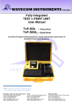
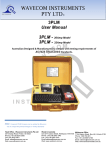
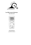
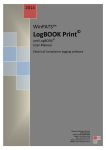
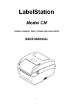
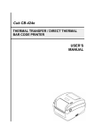
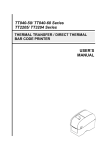
WAVECOM INSTRUMENTS PTY LTD© www.wavecom.com.au WAVECOM TT040-50 THERMAL TRANSFER BAR CODE PRINTER USER MANUAL Wavecom Instruments Thermal Transfer Bar Code Printer User Manual 1 Wavecom Instruments Thermal Transfer Bar Code Printer User Manual Table of Contents Copyright Declaration 3 Introduction 3-4 Product Introduction Compliances Operations Overview 4-7 Printer purchased as part of Wavecom Test n Print Unit Unpacking and Inspection Printer Overview Front View Interior View Rear View Setup 8 Printer Printer purchased as part of Wavecom Test n Print Unit Printer setup when connecting to computer Loading the Media 8-10 Loading the Ribbon 11-12 LED and Button Functions 13-19 LED Indicator Regular Button Function Power on Utilities Gap/Black mark Sensor Calibration Gap/Black Mark Calibration, Self-test and Dump Mode Printer Initialization Set Black Mark Sensor as Media Sensor and Calibrate the Black Mark Sensor Set Gap Sensor as Media Sensor and Calibrate the Gap Sensor Skip AUTO.BAS (not applicable) Troubleshooting 20-21 LED Status Print Problem Maintenance 22-23 2 Wavecom Instruments Thermal Transfer Bar Code Printer User Manual Copyright Declaration Information in this document is subject to change without notice and does not represent a commitment on the part of Wavecom Instruments Pty. Ltd. No part of this manual may be reproduced or transmitted in any form by any means, for any purpose other than the purchaser’s personal use, without the expressed written permission of Wavecom Instruments Pty. Ltd. Introduction Product Introduction Thank you for purchasing Wavecom bar code printer. Although the printer has a small footprint, it delivers reliable, superior performance. This printer provides direct thermal printing at user selectable speed of: 2.0, 3.0, 4.0 or 5.0 ips. It accepts roll feed and die-cut media with gap or black mark. All common bar codes formats are available. Fonts and bar codes can be printed in 4 directions, 8 different alphanumeric bitmap fonts and built-in scalable font capability. You will enjoy trouble free, high throughput for printing labels with this printer. NOTE: - You can also try SPECIAL WHITE LEADER Wavecom colour labels designed for easy Barcode colour scanning. Compliances CE Class B: EN55022: 1998+A1: 2000+A2: 2003 EN55024: 1998+A1: 2001+A2: 2003 IEC 61000-4 Series EN61000-3-2: 2006 & EN61000-3-3: 1995+A1: 2001 FCC Part 15, Class B UL, CUL: UL60950-1 C-Tick: rd CFR 47, Part 15/CISPR 22 3 Edition: 1997, Class B ANSI C63.4: 2003 Canadian ICES-003 TÜV/Safety: EN60950-1 / IEC 60950-1 3 Wavecom Instruments Thermal Transfer Bar Code Printer User Manual CAUTION 1. THE MAIN BOARD INCLUDES A REAL TIME CLOCK FEATURE AND HAS A LITHIUM BATTERY INSTALLED. 2. RISK OF EXPLOSION IF BATTERY IS REPLACED BY INCORRECT TYPE 3. DISPOSE OF USED BATTERIES ACCORDING TO THE MANUFACTURER INSTRUCTIONS Note: The maximum printing ratio per dot line is 15% for this printer. To print the full web black line, the maximum black line height is limited to 40 dots, which is 5mm for 203 DPI resolution printer and 3.3mm for 300 DPI resolution printer. Operations Overview Printer purchased as part of Wavecom Test n Print Pack When TT040-50 is purchased as part of a Wavecom Test n Print Unit, the Printer is ready and fully setup to use. Owner’s Barcode Label Artwork may be installed as an option. Unpacking and Inspection This printer has been specially packaged to withstand damage during shipping. Please carefully inspect the packaging and printer upon receiving the bar code printer. Please retain the packaging materials in case you need to reship the printer. Unpacking the System, the following items are included in the carton. One printer unit User Manual, quick start guide and Drivers on the WinPATS CD One quick start installation guide One power cord One auto switching power supply One USB interface cable One paper core 4 Wavecom Instruments Thermal Transfer Bar Code Printer User Manual If any parts are missing, please contact your Supplier or Wavecom Instruments. Printer Overview Front View 4 1 2 1. LED indicator 2. Feed button 3 3. Paper exit chute 4. Media view window 5. Top cover open lever 5 5 Wavecom Instruments Thermal Transfer Bar Code Printer User Manual Interior View 1 2 3 4 5 14 6 7 8 9 10 12 11 13 1. Ribbon access cover 2. Ribbon rewind hub 3. Ribbon rewind gear 8. Media guide 9. Top cover support 10. Black mark sensor 4. Print head 5. Ribbon supply hub 6. Gap sensor (receiver) 7. Media holders 11. Platen roller 12. Gap sensor (transmitter) 13. Media guide adjuster knob 14. Top cover 6 Wavecom Instruments Thermal Transfer Bar Code Printer User Manual Rear View 1 6 2 4 5 3 1. Power switch 2. Power jack socket 3. USB interface 4. USB host (Factory option) 5. RS-232C interface / Ethernet interface (Option) 6. SD card socket (Not Applicable to this unit) 7 Wavecom Instruments Thermal Transfer Bar Code Printer User Manual Setup Printer Printer purchased as part of Wavecom Test n Print Pack Printer when purchased as part of a Wavecom Test n Print Unit is already fully setup and ready to use. Printer setup when connecting to computer Place the printer on a flat, secure surface. Make sure the power switch is set to “off”. Connect the printer to the computer with the provided USB cable. Plug the power cord into the AC power cord socket at the rear of the printer, and then plug the power cord into a properly grounded power outlet. Note: Please switch OFF printer power switch prior to plug in the power cord to printer power jack. Loading the Media Loading the Media Open the printer top cover by pulling the tabs located on each side towards the front of the printer, and then lift the top cover to the maximum open angle. 8 Wavecom Instruments Thermal Transfer Bar Code Printer User Manual Separate the media holders to the label roll width. Place the roll between the holders and close them onto the core. Place the paper, printing side face up, through the media guides, media sensor and place the label leading edge onto the platen roller. 9 Wavecom Instruments Thermal Transfer Bar Code Printer User Manual Move the media guides to fit the label width by turning the media guide adjuster knob. Hold the top cover and press the top cover support to disengage the top cover support with lower inner cover. Gently close the top cover. Make sure the cover latches securely. 10 Wavecom Instruments Thermal Transfer Bar Code Printer User Manual Loading the Ribbon 1. Open the printer’s top cover by pulling the top cover open levers located on each side of the printer and lifting the top cover to the maximum open angle. 2. Insert the ribbon right side onto the supply hub. Align the notches on the left side and mount onto the spokes. 3. Open the ribbon access cover. 4. Insert the paper core right side onto the rewind hub. Align the notches on the left side and mount onto the spokes 11 Wavecom Instruments Thermal Transfer Bar Code Printer User Manual 5. Pull the leading ribbon to pass the print head. 6. Stick the ribbon onto the ribbon rewind paper 7. Turn the ribbon rewind gear until the ribbon plastic leader is thoroughly wound and the black section of the ribbon covers the print head. Close the ribbon access cover and the top cover. 12 Wavecom Instruments Thermal Transfer Bar Code Printer User Manual LED and Button Functions This printer has one button and one three-color LED indicator. By indicating the LED with different color and pressing the button, printer can feed labels, pause the printing job, select and calibrate the media sensor, print printer self-test report, reset printer to defaults (initialization). Please refer to the button operation below for different functions. LED Indicator LED Color Description Green/ Solid This illuminates that the power is on and the device is ready to use. Green/ Flash Amber Red / Solid This illuminates that the system is downloading data from PC to memory or the printer is paused. This illuminates that the system is clearing data from printer. This illuminates printer head open, cutter error. This illuminates a printing error, such as head open, paper Red / Flash empty, paper jam or memory error etc. Regular Button Function 1. Feed labels When the printer is ready, press the button to feed one label to the beginning of next label. 2. Pause the printing job When the printer is printing, press the button to pause a printing job. When the printer is paused, the LED will be green blinking. Press the button again to continue the printing job. 13 Wavecom Instruments Thermal Transfer Bar Code Printer User Manual Power on Utilities There are six power-on utilities to set up and test printer hardware. These utilities are activated by pressing FEED button then turning on the printer power simultaneously and release the button at different color of LED. Please follow the steps below for different power-on utilities. 1. Turn off the power switch. 2. Hold on the button then turn on the power switch. 3. Release the button when LED indicates with different color for different functions. Power on utilities The LED color will be changed as following pattern: LED color Amber Red Amber Green Functions (5 blinks) (5 blinks) (5 blinks) 1. Gap / black mark sensor calibration Release 2. Gap / black mark sensor calibration, Green/Amber Red/Amber Solid green (5 blinks) (5 blinks) Release Self-test and enter dump mode 3. Printer initialization Release 4. Set black mark sensor as media Release sensor and calibrate the black mark sensor 5. Set gap sensor as media sensor and Release calibrate the gap sensor 6. Skip AUTO.BAS Release Gap/Black Mark Sensor Calibration Gap/black mark sensor sensitivity should be calibrated at the following conditions: 1. A brand new printer 2. Change label stock. 3. Printer initialization. Please follow the steps below to calibrate the gap/black mark sensor. 1. Turn off the power switch. 2. Hold on the button then turn on the power switch. 3. Release the button when LED becomes red and blinking. (Any red will do during the 5 links). It will calibrate the gap/black mark sensor sensitivity. The LED color will be changed as following order: Amber red (5 blinks) amber (5 blinks) green (5 blinks) green/amber (5 blinks) red/amber (5 blinks) solid green Note: 1. Sensor calibration can be done by the power on utility. 2. Please select gap or black mark sensor type prior to calibrate the sensor. 14 Wavecom Instruments Thermal Transfer Bar Code Printer User Manual Gap/Black Mark Calibration, Self-test and Dump Mode While calibrate the gap/black mark sensor, printer will measure the label length, print the internal configuration (self-test) on label and then enter the dump mode. To calibrate gap or black mark sensor depends on the sensor setting in the last print job. Please follow the steps below to calibrate the sensor. 1. Turn off the power switch. 2. Hold on the button then turn on the power switch. 3. Release the button when LED becomes amber and blinking. (Any amber will do during the 5 blinks) The LED color will be changed as following order. Amber red (5 blinks) amber (5 blinks) green (5 blinks) green/amber (5 blinks) red/amber (5 blinks) solid green 4. It calibrates the sensor and measures the label length and prints internal settings then enter the dump mode. Note: 1. Sensor calibration can be done by power on utility. 2. Please select gap or black mark sensor type prior to calibrate the sensor. 15 Wavecom Instruments Thermal Transfer Bar Code Printer User Manual Self-test Printer will print the printer configuration after gap/black mark sensor calibration. Self-test printout can be used to check if there is any dot damage on the heater element, printer configurations and available memory space. Print head test pattern Printer model name & Main board firmware version Printed mileage Main board firmware checksum Serial port setting Code page Country code Print speed Print darkness Label size (width, height) Gap size (vertical gap, offset) Sensor sensitivity File management information 16 Wavecom Instruments Thermal Transfer Bar Code Printer User Manual Dump mode Printer will enter dump mode after printing printer configuration. In the dump mode, all characters will be printed in 2 columns as following. The left side characters are received from your system and right side data are the corresponding hexadecimal value of the characters. It allows users or engineers to verify and debug the program. Hex decimal data related to left column of ASCII data ASCII Data Note: 1. Dump mode requires 2” wide paper width. 2. Turn off / on the power to resume printer for normal printing. 3. Press FEED button to back to the previous menu. 17 Wavecom Instruments Thermal Transfer Bar Code Printer User Manual Printer Initialization Printer initialization is used to clear DRAM and restore printer settings to defaults. Printer initialization is activated by the following procedures. 1. Turn off the power switch. 2. Hold on the button then turn on the power switch. 3. Release the button when LED turns green after 5 amber blinks. (Any green will do during the 5 blinks). The LED color will be changed as following: Amber red (5 blinks) amber (5 blinks) green (5 blinks) green/amber (5 blinks) red/amber (5 blinks) solid green Printer configuration will be restored to defaults as below after initialization. Parameter Speed Default setting 127 mm/sec (5 ips) (203DPI) 76.2 mm/sec (3 ips) (300DPI) Density 8 Label Width 2” (50.8 mm) Label Height 2” (50.8 mm) Sensor Type Gap sensor Gap Setting 0.12” (3.0 mm) Print Direction 0 Reference Point 0,0 (upper left corner) Offset 0 Tear Mode On Peel off Mode Off Cutter Mode Off Serial Port Settings 9600 bps, none parity, 8 data bits, 1 stop bit Code Page 850 Country Code 001 Clear Flash Memory No IP Address DHCP 18 Wavecom Instruments Thermal Transfer Bar Code Printer User Manual Set Black Mark Sensor as Media Sensor and Calibrate the Black Mark Sensor Please follow the steps as below. 1. Turn off the power switch. 2. Hold on the button then turn on the power switch. 3. Release the button when LED turns green/amber after 5 green blinks. (Any green/amber will do during the 5 blinks). The LED color will be changed as following: Amber red (5 blinks) amber (5 blinks) green (5 blinks) green/amber (5 blinks) red/amber (5 blinks) solid green Set Gap Sensor as Media Sensor and Calibrate the Gap Sensor Please follow the steps as below. 1. Turn off the power switch. 2. Hold on the button then turn on the power switch. 3. Release the button when LED turns red/amber after 5 green/amber blinks. (Any red/amber will do during the 5 blinks). The LED color will be changed as following: Amber red (5 blinks) amber (5 blinks) green (5 blinks) green/amber (5 blinks) red/amber (5 blinks) solid green Skip AUTO.BAS (not applicable) TSPL2 programming language allows user to download an auto execution file to flash memory. Printer will run the AUTO.BAS program immediately when turning on printer power. The AUTO.BAS program can be interrupted without running the program by the power-on utility. Please follow the procedures below to skip an AUTO.BAS program. 1. Turn off printer power. 2. Press the FEED button and then turn on power. 3. Release the FEED button when LED becomes solid green. The LED color will be changed as following: Amber red (5 blinks) amber (5 blinks) green (5 blinks) green/amber (5 blinks) red/amber (5 blinks) solid green 4. Printer will be interrupted to run the AUTO.BAS program. 19 Wavecom Instruments Thermal Transfer Bar Code Printer User Manual Troubleshooting The following guide lists the most common problems that may be encountered when operating this bar code printer. If the printer still does not function after all suggested solutions have been invoked, please contact the Customer Service Department of your purchased reseller or distributor for assistance. LED Status This section lists the common problems that according to the LED status and other problems you may encounter when operating the printer. Also, it provides solutions. LED Status / Color OFF Printer Status Possible Cause Recovery Procedure No response No power * Turn on the power switch. * Check if the green LED is lit on power supply. If it is not lit on, power supply is broken. * Check both power connections from the power cord to the power supply and from the power supply to the printer power jack if they are connected securely. Solid Green ON The printer is * No action necessary. ready to use Green with Pause blinking Red with blinking Error The printer is * Press the FEED button to resume for paused printing. The out of label or 1. Out of label the printer setting is not correct * Load a roll of label and follow the instructions in loading the media then press the FEED button to resume for printing. 2. Printer setting is not correct * Initialize the printer by instructions in “Power on Utility”. 20 Wavecom Instruments Thermal Transfer Bar Code Printer User Manual Print Problem Problem Possible Cause Check if interface cable is well Recovery Procedure Re-connect cable to interface. connected to the interface connector. The serial port cable pin configuration Please replace the cable with pin to Not Printing No print on the label Continuous feeding labels is not pin to pin connected. pin connected. The serial port setting is not Please reset the serial port setting. consistent between host and printer. The port specified in the Windows Select the correct printer port in the driver is not correct. driver. The Ethernet IP, subnet mask, Configure the IP, subnet mask and gateway is not configured properly. gateway. Label loaded not correctly. The printer setting may go wrong. Gap/black mark sensor sensitivity is Follow the instructions in loading the media. Please do the initialization and gap/black mark calibration. Calibrate the gap/black mark sensor. not set properly (sensor sensitivity is not enough) Paper Jam Set label size exactly as installed paper in the labeling software or program. Labels may be stuck inside the printer Remove the stuck label. Make sure label size is set properly. mechanism near the sensor area. Top cover is not closed properly. Wrong power supply is connected Close the top cover completely and make sure the right side and left side levers are latched properly. Check if 24V DC output is supplied by the power supply. with printer. Poor Print Quality Check if supply is loaded correctly. Reload the supply. Check if dust or adhesives are Clean the print head. accumulated on the print head. Adjust the print density and print speed. Check print head test pattern if head Run printer self-test and check the print head test pattern if there is dot element is damaged. missing in the pattern. Check if print density is set properly. 21 Wavecom Instruments Thermal Transfer Bar Code Printer User Manual Maintenance This session presents the clean tools and methods to maintain your printer. 1. Please use one of following material to clean the printer. Cotton swab (Head cleaner pen) Lint-free cloth Vacuum / Blower brush 100% ethanol 2. The cleaning process is described as following: Printer Part Method Interval 1. Always turn off the printer before cleaning the print head. Clean the print head when changing a new label roll 2. Allow the print head to cool for a minimum of one minute. 3. Use a cotton swab and 100% ethanol to clean the print head surface. Print Head Platen Roller 1. Turn the power off. Clean the platen roller when 2. Rotate the platen roller and wipe it changing a new label roll thoroughly with 100% ethanol and a cotton swab, or lint-free cloth. Tear Bar/Peel Use the lint-free cloth with 100% ethanol to As needed Bar wipe it. Sensor Compressed air or vacuum Monthly Exterior Wipe it with water-dampened cloth As needed Interior Brush or vacuum As needed 22 Wavecom Instruments Thermal Transfer Bar Code Printer User Manual Note: Do not touch printer head by hand. If you touch it accidently, please use ethanol to clean it. Please use 100% Ethenol. DO NOT use medical alcohol, which may damage the printer head. Regularly clean the print head and supply sensors when changing media to keep optimal performance and extend printer life. The maximum printing ratio per dot line is 15% for this printer. To print the full web black line, the maximum black line height is limited to 40 dots, which is 5mm for 203 DPI resolution printer and 3.3mm for 300 DPI resolution printer. 23 Head Office – Wavecom Instruments Pty Ltd Melbourne Office 257 Grange Road 772A Station Street Findon SA 5023 Box Hill VIC 3128 Ph: (08) 8243 3500 Fax: (08) 8243 3501 Ph: 1300 793 301 Fax: (03)9897 4766 Email: [email protected] Email: [email protected] www.wavecom.com.au