1
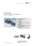
MS 157E User Manual C-809.D40 Interface for Delta Tau Controller Release: 1.0.0 Date: 2006-02-22 This document describes the following product(s): C-809.D40 Interface for Delta Tau Controller © Physik Instrumente (PI) GmbH & Co. KG Auf der Römerstr. 1 ⋅ 76228 Karlsruhe, Germany Tel. +49 721 4846-0 ⋅ Fax: +49 721 4846-299 [email protected] ⋅ www.pi.ws C-809.D40 Adaptor Electronics User Manual MS 157E Table of Contents: 0. Manufacturer Declarations .............................................. 2 0.1. Declaration of Conformity ............................................................ 2 0.2. Safety Precautions....................................................................... 2 1. Introduction....................................................................... 3 1.1. About This Manual ....................................................................... 3 1.2. C-809 Description ........................................................................ 3 1.2.1. Front Panel Elements .................................................................. 3 1.2.2. AC Power Connection.................................................................. 3 2. Operation........................................................................... 4 2.1. Quick Start ................................................................................... 4 2.2. Power Supply Settings................................................................. 4 3. Connectors and Pinouts .................................................. 5 3.1. Motor Connector .......................................................................... 5 3.2. 24 V Power-Out Sockets.............................................................. 5 3.3. Controller Connector.................................................................... 6 4. Technical Data .................................................................. 7 4.1. Specifications............................................................................... 7 4.2. Layout Diagram............................................................................ 8 4.3. Circuit Diagram Details ................................................................ 9 © Copyright 2006 by Physik Instrumente (PI) GmbH & Co. KG Release: 1.0.0 File:C-809_D40_User_MS157E100.doc, 313856 Bytes Release 1.0.0 www.pi.ws Page 1 C-809.D40 Adaptor Electronics User Manual MS 157E 0. Manufacturer Declarations 0.1. Declaration of Conformity The manufacturer, Physik Instrumente (PI) GmbH & Co. KG Auf der Roemerstrasse 1 76228 Karlsruhe, Germany declares, that the product C-809 Motion I/O Interface complies with these specifications: EMC: EN55022 (1991), Group1, Class B EN50082-1 (1992) / IEC 801-2:1991 (4 kV Contact Discharge) (8 kV Air Discharge) EN50082-1 (1992) / IEC 801-3: 1984 (3V/m) EN50082-1 (1992) / IEC 801-4: 1988 (1 kV power lines, 0.5 kV Signal lines) Safety: IEC 1010-1:1990+A1 / EN61010-1:1993 (Low-Voltage Directive) The product complies with the requirements of the EMC Directive 89/336/EEC and CE markings have been affixed on the devices. 0.2. Safety Precautions Warning: High Voltage Disconnect the C-809 from the line voltage before opening the case. Procedures which require opening the case should be carried out by authorized, qualified personnel only. Caution: Use 24 V Power out sockets only for driving motors. The four 24 V Power out sockets are designed to drive DC motors. Using it for other purposes could cause permanent damage to the C-809. Caution: PMAC card setup If the jumpers JP1 and JP2 are set on the C-809 board to supply the PMAC card, the PMAC card must be operated with isolated setup to avoid damage of the electronics (see the documentation of the PMAC card for details). Release 1.0.0 www.pi.ws Page 2 C-809.D40 Adaptor Electronics User Manual MS 157E 1. Introduction 1.1. About This Manual This manual contains information concerning the operation of the C-809 Motion I/O Interface. 1.2. C-809 Description The C-809 Motion I/O Interface houses adaptor electronics that allows running a wide range of PI micropositioning stages with the PMAC Delta Tau controller. The C-809 is designed as a 19” rackmount unit and makes the full functionality of the controller available for up to 4 analog or PWM (e.g. PI’s ActiveDrive™ line) servo-motors from PI. With its integrated power supplies the C-809 can drive all kinds of DC motors from PI. DC analog motors, with up to 10 W power each, can be driven directly. For the more powerful PWM DC motors, the C-809 features a 4-channel power supply which provides 24 V per channel. The PWM signals are generated by the C-809 based on analog signals from the controller card. 1.2.1. Front Panel Elements Fig. 1: C-809.D40 Motion Interface front panel Connector Function Motor 1 Motor 2 Motor 3 Motor 4 Connectors for PI stages 24 V Power out (4x) Power supply for PWM stages (e.g. ActiveDrive™), 4 x 24 V 4 x DB 15f, for pinouts see Section 3.1, p. 5 Switchcraft 3-pin, for pinouts see Section 3.2, p. 5, use the power cables that come with the C-809 (4 x C-815.PS3) Controller Interface to the Motion Control card 1.2.2. AC Power Connection The power connection and line fuses are located on the rear panel. The C-809 is equipped with a wide-range power supply and with fuses that are admissible for both 115 V and 230 V operation. No settings need be changed when connecting a C-809 to a different supply voltage. Release 1.0.0 www.pi.ws Page 3 C-809.D40 Adaptor Electronics User Manual MS 157E 2. Operation 2.1. Quick Start To operate your motion system using the C-809 adaptor electronics proceed as follows: Install the PMAC Delta Tau motor controller card. Connect C-809 to AC Power. The wide-range power supply works with line voltages from 90 to 240 volts AC at 50 to 60 Hz. With the C-809 switched OFF, establish the connection between the C-809 box and the controller. Connect the C-809 to up to four PI stages using the Motor1 to Motor4 connectors. Every PWM stage (see the stage’s User Manual for model number and description) must also be connected to a 24 V Power out connector. For this purpose use one of the 4 power cables C-815.PS3 that come with the C-809. A mix of analog and PWM stages may be connected to the C-809. Power up the C-809 by switching on the unit (rocker switch is located near the power cord socket on the rear panel). 2.2. Power Supply Settings Warning: High Voltage Disconnect the C-809 from the line voltage before opening the case. Procedures which require opening the case should be carried out by authorized, qualified personnel only. Caution: PMAC card setup If the jumpers JP1 and JP2 are set on the C-809 board to supply the PMAC card, the PMAC card must be operated with isolated setup to avoid damage of the electronics. By default, the jumpers JP1 and JP2 (see p. 8) are not set. So the output amplifiers of the PMAC card are not powered by the C-809 (non-isolated setup, see the documentation of the PMAC card for more information). By setting the jumpers JP1 and JP2 the PMAC card can be supplied by the C-809. In this case the PMAC card must be in isolated setup (see the documentation of the PMAC card for details). Release 1.0.0 www.pi.ws Page 4 C-809.D40 Adaptor Electronics User Manual MS 157E 3. Connectors and Pinouts 3.1. Motor Connector The motor connectors 1 to 4 follow standard conventions for PI analog and PWM stages. Note that if you operate a PWM stage, a C-815.PS3 power cable (see Section 3.2) is required in addition to connect to a 24 V Power out socket (see below). Pin Assignment (15-pin subD(f) connector): Pin 1 9 2 10 3 11 4 12 5 13 6 14 7 15 8 Function Brake Motor ( - ) Motor (+) Power-GND Magnitude (PWM) Sign (PWM) Out +5 V Input : Negative Limit Input:: Positive Limit Input:: Reference Limit GND Encoder: A (+) / ENCA Encoder: A ( - ) Encoder: B (+) / ENCB Encoder: B ( - ) 3.2. 24 V Power-Out Sockets The four 24 V Power out connectors are interchangeable, ready for use with PWM stages; no activation is required. 3-pin socket, Switchcraft 1 GND 2 +24 V 3 unused Release 1.0.0 www.pi.ws Page 5 3.3. C-809.D40 Adaptor Electronics User Manual MS 157E Controller Connector The 60-pin Controller connector is for the cable connecting the C-809 with the Delta Tau Controller. Pin Assignment (60-pin connector): Function not used GND (Power Ground) not used not used CHB3+ (Encoder 3, B+) CHB3- (Encoder 3, B-) CHA3+ (Encoder 3, A+) CHA3- (Encoder 3, A-) not used not used CHB1+ (Encoder 1, B+) CHB1- (Encoder 1, B-) CHA1+ (Encoder 1, A+) CHA1- (Encoder 1, A-) DAC3 (Motor analog +/-10 V, ch3) Not used AENA3 (Amplifier enable, ch3) FAULT3 +LIM3 (Limit positive, ch3) -LIM3 (Limit negative, ch3) HMFL (Reference, ch3) DAC1 (Motor analog +/-10 V, ch1) Not used AENA1 (Amplifier enable, ch1) FAULT1 +LIM1 (Limit positive, ch1) -LIM1 (Limit negative, ch1) HMFL1 (Reference, ch1) Not used + 15 V (JP1) Release 1.0.0 Pin 1 3 5 7 9 11 13 15 17 19 21 23 25 27 29 31 33 35 37 39 41 43 45 47 49 51 53 55 57 59 Pin 2 4 6 8 10 12 14 16 18 20 22 24 26 28 30 32 34 36 38 40 42 44 46 48 50 52 54 56 58 60 Function not used GND (Power Ground) not used not used CHB4+ (Encoder 4, B+) CHB4- (Encoder 4, B-) CHA4+ (Encoder 4, A+) CHA4- (Encoder 4, A-) not used not used CHB2+ (Encoder 2, B+) CHB2- (Encoder 2, B-) CHA2+ (Encoder 2, A+) CHA2- (Encoder 2, A-) DAC4 (Motor analog +/-10 V, ch4) Not used AENA4 (Amplifier enable, ch4) FAULT4 +LIM4 (Limit positive, ch4) -LIM4 (Limit negative, ch4) HMFL4 (Reference, ch4) DAC2 (Motor analog +/-10 V, ch2) Not used AENA2 (Amplifier enable, ch2) FAULT2 +LIM2 (Limit positive, ch2) -LIM2 (Limit negative, ch2) HMFL2 (Reference, ch2) GND -15 V (JP2) www.pi.ws Page 6 C-809.D40 Adaptor Electronics User Manual MS 157E 4. Technical Data 4.1. Specifications Model C-809.D40 Function Interface for PMAC Delta Tau controller card Axes 4 Output Power per channel Analog DC Motors (on motor connector): 10 watts PWM Stages (on separate power out socket): max. 100 watts* Max. output power (total for an arbitrary mix of four stages) 100 VA Current limitation 2 A per channel for analog DC motors (short-circuit proof) PWM signal 20-22 kHz, TTL Motor connectors 15-pin (f) sub-D per channel Motion I/O connector 60 flat ribbon connector socket 24 V Power out sockets (4x) 3-pin Switchcraft, only for driving motors Size 450 x 105 x 390 mm Power supply wide range, 90 to 240 V AC at 50 to 60 Hz *100 watts are achieved if only one PWM stage and no analog stage is connected to the C-809. Release 1.0.0 www.pi.ws Page 7 C-809.D40 Adaptor Electronics User Manual MS 157E 4.2. Layout Diagram JP1 JP2 Release 1.0.0 www.pi.ws Page 8 C-809.D40 Adaptor Electronics User Manual MS 157E 4.3. Circuit Diagram Details See the next pages. Release 1.0.0 www.pi.ws Page 9