1
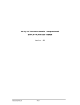
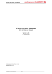
EDP-AM-AN16 Analog Input Applications
Module User Manual
This document contains information on the AN16 analog input module for the
RS EDP system.
Version v5.0, 10/06/2010
EDP-AM-AN16 Manual
Contents 1. 1.1 1.2 1.3 1.3
1.4 1.5 1.5.1 1.5.2 1.6 Analog Input Module
3 Anti-Aliasing Filters ......................................................................... 3 Additional Items............................................................................... 4 Setting Jumper Options................................................................... 4 Software Drivers For Analog Module .............................................. 6 Mapping Of CPU Peripheral Pins To The Analog Module .............. 6 Analog Module Input Characteristics .............................................. 7 Channels AN0-AN7 ......................................................................... 7 Channels AN8- AN15 ...................................................................... 8 Analog Module Hints ....................................................................... 9 © Electrocomponents plc
Page 2
EDP-AM-AN16 Manual
1. Analog Input Module
The EDP-AM-AN16-A analog module allows up to 32 analog channels to be interfaced to the CM
(CPU Module or Command Module). It has a mix of filtered and unfiltered inputs and two precision
voltage sources for accurate absolute measurements.
The on-board MAX1138 ADC is accessible via I2C CNTRL bus and gives up to 12 extra channels of
10-bit analog to digital conversion. Each of the first 12 channels can be routed via jumpers to either
the CM’s own ADC or to the on-board ADC. In addition, any unused channels on the on-board ADC is
available on a connector, meaning a total of 16 plus 12, i.e.28 channels are possible.
Two analog modules may be fitted simultaneously. If this is the case the 16 analog channels, which
are fed directly down the backplane to the ADC on the MCU have to be allocated to each of the two
modules respectively but the 12 additional ADC channels present on each of the AMs can be read
independently, giving a total of 16 plus 12 plus a second 12. i.e. a total of 40 channels.
If a second module is fitted, the channels belonging to the CM remain the same, although the user can
specify which channel will be routed through which analog module. The second analog module must
use the second I2C channel, I2C_GEN0 as the MAX1138 ADC has a fixed I2C address. An
alternative version of this device (MAX1138KEEE+) has a different I2C address and can be fitted to
the second module if required.
The on-board ADC is by default the MAX1138 5V, 10-bit ADC but the alternative MAX1139 3V3
device can be fitted. The CM analog channels have a voltage range determined by the CPU fitted.
The analog module inputs are able to cope with a 0-5V range, regardless of the CM type fitted. It is
therefore up to the user to ensure that the voltage applied to the inputs does not exceed that required
by the CM. A series protection resistor may optionally be fitted to reduce the chance of damaging a
3V3 ADC if 5V is applied.
The 5V and 3V3 precision references can be applied to the CM’s ADC and the on-board ADC,
although the latter will sacrifice one channel if this is used. They can also be fed back to the CM via
the VAREF EDP signal.
Ratiometric conversions are possible using a special output pin on connector P201 pin1 for driving
resistive sensors.
Quantity 2 6 8 12 1 1 Type 2 pole filters with digitally controlled cut‐off
2‐pole active filters with fixed cut‐off
1‐pole passive filters with fixed cut‐off
Unfiltered channels 5V reference
3V3 reference
1.1 Anti-Aliasing Filters
Channels AN0 to AN7 are equipped with 2-pole, Sallen-Key anti-aliasing filters, configured in a
Butterworth mode.
The active filters are unity gain so they can be used for DC voltage
measurements as well as for sampling rapidly changing signals. Channels AN0 and AN1 optionally
have I2C-controlled 256 step digital potentiometers which allow the filter characteristics to be altered
under software control. They can also be cascaded to yield a single 4-pole filter on channel AN0.
The remaining active filters have a cut-off frequency of 12kHz.
By fitting the appropriate resistors to the potential dividers on the filter inputs (R301, R304 etc.), the
input voltage range can be extended to suit the user’s application on a channel-by-channel basis.
© Electrocomponents plc
Page 3
EDP-AM-AN16 Manual
AN8-AN15 have simple low-pass filter inputs. All inputs are protected against over-voltage conditions.
1.2 Additional Items
A trimmer potentiometer and light-dependent resistor and are fitted to channels AN0 and AN1
respectively for educational purposes.
1.3 Setting Jumper Options
Some options are made using black 2mm links. These are available from RS under part number 1809353. The possible user settings are listed below, along with their default configurations.
Jumper
Type
Purpose
J202
Solder
Set voltage for MAX1138 ADC
J204
J205
J301
J302
J303
J305
J306
J307
J308
J309
J310
J311
J312
J313
J314
J201
JP201
JP202
JP203
JP204
JP205
JP206
JP301
JP302
P201
Solder
Solder
Solder
Solder
Solder
Solder
Solder
Solder
Solder
Solder
Solder
Solder
Solder
Solder
Solder
4W Link
Link
Link
Link
Link
Link
Link
Link
Link
2-way
© Electrocomponents plc
Default
1-2
Set I2C channel
Set I2C channel
Connect local VAGND to SGND on module rather on CPU module (NO)
Route AN0_5V to CPU AN0 or MAX1138 AN0; enable 5V to 3V3 scaling for CPU AN0
Enable shutdown mode for AD5263 (Default 2-3)
Set AD5263 I2C address AD0
Set AD5263 I2C address AD1
Create 4-pole active filter from U301A and U301B
Route AN4_5V to CPU AN4 or MAX1138 AN4; enable 5V to 3V3 scaling for CPU AN4
Route AN1_5V to CPU AN1 or MAX1138 AN1; enable 5V to 3V3 scaling for CPU AN1
Route AN5_5V to CPU AN5 or MAX1138 AN5; enable 5V to 3V3 scaling for CPU AN5
Route AN6_5V to CPU AN6 or MAX1138 AN6; enable 5V to 3V3 scaling for CPU AN6
Route AN2_5V to CPU AN2 or MAX1138 AN2; enable 5V to 3V3 scaling for CPU AN2
Route AN7_5V to CPU AN7 or MAX1138 AN7; enable 5V to 3V3 scaling for CPU AN7
Route AN3_5V to CPU AN3 or MAX1138 AN3; enable 5V to 3V3 scaling for CPU AN3
Select source for MAX1138 REF
Select ADC for AN8_5V input
Select ADC for AN9_5V input
Select ADC for AN10_5V input
Select voltage for VAREF
Select ADC for AN11_5V input
Select source for AN15 input
Select AN0_5V or pot as AN0 input
Select AN1_5V or LDR as AN1 input
Power supply to ratiometric sensors
Page 4
1-2
1-2
1-2
1-2
2-3
2-3
2-3
Open
1-2
1-2
1-2
1-2
1-2
1-2
1-2
Open
1-2
1-2
1-2
1-2
1-2
2-3
1-2
1-2
NC
EDP-AM-AN16 Manual
The locations of the most important user-selectable items are shown below.
P203: Direct 5V analog input
to MAX1138
J201: Select source for MAX1138 REF
JP204: Select voltage for VAREF
JP206: Select source for AN15
JP202: Select ADC for AN9_5V
JP201:Select ADC for AN8_5V
JP205:Select ADC for AN11_5V
JP203: Select ADC for AN10_5V
J202: Set voltage for MAX1138 ADC
JP302: Select AN1_5V or LDR as AN1 input:
J205: Set I2C channel
J204: Set I2C channel
J305: Set AD5263 I2C address AD0
JP301: Select AN0_5V or pot as AN0 input
J306: Set AD5263 I2C address AD1
J302: Route AN0_5V to CPU AN0 or MAX1138 AN0; enable 5V to 3V3 scaling for CPU AN0
J309 :Route AN1_5V to CPU AN1 or MAX1138 AN1; enable 5V to 3V3 scaling for CPU AN1
J307: Create 4-pole active filter
J312: Route AN2_5V to CPU AN2 or MAX1138 AN2; enable 5V to 3V3 scaling for CPU AN2
J303: Enable shutdown mode for AD5263 (Default 2-3)
J314: Route AN3_5V to CPU AN3 or MAX1138 AN3; enable 5V to 3V3 scaling for CPU AN3
J310: Route AN5_5V to CPU AN5 or MAX1138 AN5; enable 5V to 3V3 scaling for CPU AN5
J308: Route AN4_5V to CPU AN4 or MAX1138 AN4; enable 5V to 3V3 scaling for CPU AN4
P202: 5V analog inputs to
CPU ADC or MAX1138
J311: Route AN6_5V to CPU AN6 or MAX1138 AN6; enable 5V to 3V3 scaling for CPU AN6
J313: Route AN7_5V to CPU AN7 or MAX1138 AN7; enable 5V to 3V3 scaling for CPU AN7
J301: Connect local VAGND to SGND on module rather on CPU module (NO)
P201: Power supply to ratiometric sensors
AN16 ‐ Analogue Module to RS‐EDP Backplane
P202 Analogue
Input Connector
AN0
AN1
AN2
AN3
AN4
AN5
AN6
AN7
AN8
AN9
AN10
AN11
AN12
AN13
AN14
AN15
CNTRL I2C
2
1
JP204
3
I2C GEN0
JP206
3
1
JP312
1
JP314
1
JP308
1
JP310
1
JP311
1
JP313
1
JP201
1
JP202
1
JP203
1
JP205
1
I2C Data
I2C CLK
2
JP205
2
3
1
2
3
2
3
2
3
2
3
2
3
2
3
2
3
2
3
2
3
2
3
2
3
AN0_5V
AN1_5V
AN2_5V
AN3_5V
AN4_5V
AN5_5V
AN6_5V
AN7_5V
AN8_5V
AN9_5V
AN10_5V
AN11_5V
AN12_5V
AN13_5V
AN14_5V
AN15_5V
I2C
J301
SGND
VAGND
VAREF
1
JP309
3
1
2
1
JP301
2
JP204
1
3
3.3Vref
5.0Vref
I2C bus can only read inputs AN0_5V to AN11_5V
Block diagram of the Analog Module showing capability and basic link options. Normally AN0_5V to
AN15_5V are used for the raw analog inputs. The processed analog signals are passed to the MCU
via the backplane on AN0-AN15 or redirected into the on board ADC for reading via an I2C chip. With
this implementation a total of 16 analog inputs are available, the first 12 of which are readable via I2C.
You can also see that the analog ground (VAGND) and the digital signal ground (SGND) can be
connected via a zero ohm link. This link is normally left open as the same link is available on the CPU
modules. The CPU modules should normally use this option to connect the two grounds. Most of the
© Electrocomponents plc
Page 5
EDP-AM-AN16 Manual
CPU modules should have this feature but check the circuit diagram and mapping aids on the
respective CPU Modules.
The analogue board is capable of producing a very stable voltage reference signal. This signal can be
passed down the backplane as required to other modules. The CPU modules for example can use this
as a reference for their on board ADC’s. The AM is fitted with both a 3.3V and 5.0V voltage reference
source. The user selects between them as shown in the diagram. Some CPU Modules can output
their own reference on to the backplane also so the user must also check for contention on this signal
line.
The on board ADC and the digital potentiometers present on the AM can be controlled via I2C.
Normally the user would use the CNTRL_I2C bus option rather than the I2C_GEN0 bus option. The
I2C_GEN0 bus is provided as a secondary I2C interface for the customers own I2C network. Not all
CPU Modules can support the second I2C bus.
The drawing is from a Mapping Aid document which is provided for each of the CPU Modules.
1.3 Software Drivers For Analog Module
The module has two I2C devices, both of which require special software drivers to access. The
software drivers are provided for the CNTRL_I2C bus for each of the Command Modules currently in
production. The software drivers allow for the easy access to the resources available on this
Application Modules. As each piece of software is different for each of the CMs, you will need to refer
to the software pack for each of these CMs for more details.
1.4 Mapping Of CPU Peripheral Pins To The Analog Module
The analog module passes down the backplane the processed analog signals AN0 to AN15. These
may well have been processed by the on board filters on the AM for example.
The AN0-AN15 signals can be directly read by the CPU module. Not all of the CMs can read all of the
AN0-AN15 signals as the resources available on each MCU are all different. To help with the matching
up of CMs and Application Modules (AMs) a Mapping Aid document exists for each of the Command
Modules. This details the resources that are available on the MCU with the resources available on the
AMs. The page relating to the Analogue Module is shown below
The analog inputs on connector P202 on the analog IO module are connected to the CPU module as
shown below. The mapping is shown for the STR9 and XC167 modules below.
XC167 Pin Allocation Vcc to BB STR9 Pin Allocation Vcc 3V3 or 5V, supplied by CM EDP‐AM‐AN16 Allocation Vcc 3V3 or 5V, supplied by CM 42 GUARD/AN GND P3.5 P3.2 Digital GND 37 AN8 39 AN6 33 AN4 31 AN2 45 AN14 43 AN12 AVSS Analog GND P5.7 P5.6 Digital GND NC P4.6 P4.4 P4.2 NC NC VAGND IRQ_GPIO18_I2C GEN0 INT IRQ_GPIO16_CNTRL I2C INT Digital GND AN8 AN6 AN4 AN2 AN14 AN12 35 AN10 NC AN10 29 AN0 41 VAREF Vcc 5V from reg P4.0 AVREF ‐ Analog 5V from baseboard regulator AN0 AN_REF 5V from baseboard regulator © Electrocomponents plc
Page 6
EDP-AM-AN16 Manual
Vcc 3V3 from reg 3V3 from baseboard regulator 3V3 from baseboard regulator Pin XC167 Pin Allocation 126 Vcc to BB STR9 Pin Allocation Vcc 3V3 or 5V, supplied by CM EDP‐AM‐AN16 Allocation Vcc 3V3 or 5V, supplied by CM 20 132 12 10 8 6 18 16 14 4 130 AVSS Analog GND Digital GND NC P4.7 P4.5 P4.3 NC NC NC P4.1 5V from baseboard regulator 3V3 from baseboard regulator VAGND Digital GND AN9 AN7 AN5 AN3 AN15 AN13 AN11 AN1 5V from baseboard regulator 22 80 P4.0 P8.1 24 81 P4.1 P8.2 GUARD/AN GND Digital GND 38 AN9 40 AN7 34 AN5 32 AN3 46 AN15 44 AN13 36 AN11 30 AN1 Vcc 5V from reg 128 Vcc 3V3 from reg 2 NC XC167 Pin Allocation Vcc 5V from reg Vcc 3V3 or 5V, supplied by CPU Vcc 3V3 from reg 23 SDA1 24 SCL1 Digital GND 25 SDA2 26 SCL2 3V3 from baseboard regulator STR9 Pin Allocation Vcc 5V from reg Vcc 3V3 or 5V, supplied by CPU Vcc 3V3 from reg P2.3 P2.2 Digital GND P2.1 P2.0 EDP‐AM‐AN16 Allocation Vcc 5V from reg Vcc 3V3 or 5V, supplied by CPU Vcc 3V3 from reg I2C GEN0 SDA I2C GEN0 SCL Digital GND CNTRL I2C SDA CNTRL I2C SCL Refer to the Mapping Aids to get an overview of what resources the module can connect to.
1.5 Analog Module Input Characteristics
1.5.1 Channels AN0-AN7
These are over-voltage protected and buffered with unity gain, 2nd order filters. The characteristics of
the OP amps fitted mean that the usable voltage input range is 24mV to 4.49V, with a linear and
monotonic response. With a 5V, 10-bit ADC the decimal value range is from 9 to 804 bits. With a
3V3, 10-bit ADC, the upper value is 1023 bits.
© Electrocomponents plc
Page 7
EDP-AM-AN16 Manual
Buffered Analog Channel Response (5V CPUs)
Decimal 10 Bit Conversion Value
1000.00
900.00
800.00
700.00
600.00
500.00
400.00
Decimal Value
300.00
200.00
100.00
0.00
0
1000
2000
3000
4000
5000
6000
milliVolts Applied To AN0 - AN7
1.5.2 Channels AN8- AN15
These are un-buffered but still have over-voltage protection. The usable range is determined entirely
by the characteristics of the ADC used.
© Electrocomponents plc
Page 8
EDP-AM-AN16 Manual
1.6 Analog Module Hints
For best performance when using the CPU’s own ADC, i.e. least noise and greatest conversion
accuracy, ensure that the analog module is placed in the EDP baseboard position immediately
adjacent to the CPU module. Also, solder bridge J301 can be closed to ensure that the analog ground
is connected to the system ground (SGND) on the analog module rather than on the CPU module.
However to avoid ground loops though, the link on the CPU module that connects these two grounds
must be opened (XC167 only).
© Electrocomponents plc
Page 9
1
2
3
4
5
6
7
8
Module Position 1
EDPCON1 IO Connector
A
A
P101
AN_REF
AN0
AN2
AN4
AN6
AN8
AN10
AN12
AN14
1
P0P101033
P0P10105
5
P0P10107
7
P0P10109
9
P0P101011
11
P0P101013
13
P0P101015
15
P0P101017
17
P0P101019
VAGND
19
GPIO0
P0P101021
21
GPIO2_MCIDAT0
P0P101023
23
GPIO4_MCIDAT1
P0P101025
25
GPIO6_MCIDAT2
P0P101027
27
GPIO8_MCIDAT3
P0P101029
29
GPIO10_MCICLK
P0P101031
31
GPIO12_MCICMD
P0P101033
33
GPIO14_MCIPWR
P0P101035
35
IRQ_GPIO16_CNTRL I2C INTP0P101037
37
IRQ_GPIO18_I2C GEN0 INT P0P101039
39
IRQ_GPIO20_I2C GEN1 INT P0P101041
41
IRQ_GPIO22_I2C INT
P0P101043
43
GPIO24_AD7
P0P101045
45
GPIO26_AD6
P0P101047
47
GPIO28_AD5
P0P101049
49
GPIO30_AD4
P0P101051
51
GPIO32_AD3
P0P101053
53
GPIO34_AD2
P0P101055
55
GPIO36_AD1
P0P101057
57
GPIO38_AD0
P0P101059
59
EVG0_GPIO40
P0P101061
61
EVG1_GPIO42
P0P101063
63
EVG2_GPIO44
P0P101065
65
EVG3_GPIO46
P0P101067
67
EVG4_GPIO48
P0P101069
69
EVG5_GPIO50
P0P101071
71
EVG6_GPIO52
P0P101073
73
EVG7_GPIO54
P0P101075
75
EVG8_GPIO56
P0P101077
77
EVG10_GPIO58
P0P101079
79
EVG12_GPIO60
P0P101081
81
EVG14_GPIO62
P0P101083
83
EVG16_GPIO64
P0P101085
85
EVG18_GPIO66
P0P101087
87
ASC0 RX TTL
P0P101089
89
ASC0 TX TTL
P0P101091
91
ASC1 RX TTL
P0P101093
93
ASC1 TX TTL
P0P101095
95
ASC1 TX TTL_ASC0 DTR P0P101097
97
ASC1 RX TTL_ASC0 DSR P0P101099
99
SPI_SSC #CS_NSS
P0P1010101
101
ETH TX+
P0P1010103
103
ETH TXP0P1010105
105
ETH RX+
P0P1010107
107
ETH RXP0P1010109
109
ETH LNK LED
P0P1010111
111
ETH RX LED
P0P1010113
113
ETH SPD LED
P0P1010115
115
I2C GEN1 SDA
P0P1010117
117
I2C GEN1 SCL
P0P1010119
119
CAN1 RX
P0P1010121
121
CAN1 TX
P0P1010123
123
P0P1010125
VCC_CM
125
P0P1010127
+3V3
127
P0P1010129
+5V
129
P0P1010131
SGND
131
P0P1010133
+12V
133
P0P1010135
+12V
135
P0P1010137
12VGND
137
P0P1010139
12VGND
139
B
C
P0P10101
2 P0P10102
AN1
4 P0P10104
AN3
6 P0P10106
AN5
8 P0P10108
AN7
10 P0P101010
AN9
12 P0P101012
AN11
14 P0P101014
AN13
16 P0P101016
AN15
18 P0P101018
20 P0P101020
VAGND
GPIO1
P0P101022
22
GPIO3
24 P0P101024
GPIO5_I2STX_WS
26 P0P101026
GPIO7_I2SRX_CLK
28 P0P101028
GPIO9_I2SRX_WS
30 P0P101030
GPIO11_I2SRX_SDA
32 P0P101032
GPIO13_I2STX_CLK
34 P0P101034
GPIO15_I2STX_SDA
36 P0P101036
CPU DACO0_GPIO17
38 P0P101038
CPU DACO1_GPIO19
40 P0P101040
EVM0_GPIO21
42 P0P101042
EVM1_GPIO23
44 P0P101044
GPIO25_AD15
46 P0P101046
GPIO27_AD14
48 P0P101048
GPIO29_AD13
50 P0P101050
GPIO31_AD12
52 P0P101052
GPIO33_AD11
54 P0P101054
GPIO35_AD10
56 P0P101056
GPIO37_AD9
58 P0P101058
GPIO39_AD8
60 P0P101060
EVM2_GPIO41_CAPADC
62 P0P101062
EVM3_GPIO43
64 P0P101064
EVM4_GPIO45
66 P0P101066
EVM5_GPIO47
68 P0P101068
EVM6_GPIO49
70 P0P101070
EVM7_GPIO51
72 P0P101072
EVM8_GPIO53
74 P0P101074
EVM9_GPIO55
76 P0P101076
EVG9_GPIO57
78 P0P101078
EVG11_GPIO59
80 P0P101080
EVG13_GPIO61
82 P0P101082
EVG15_GPIO63
84 P0P101084
EVG17_GPIO65
86 P0P101086
EVG19_GPIO67
88 P0P101088
EVM10_GPIO68_ASC0 CTS
90 P0P101090
EVG20_GPIO69_ASC0 RTS
92 P0P101092
SPI_SSC MRST_MISO
94 P0P101094
SPI_SSC MTSR_MOSI
96 P0P101096
SPI_SSC CLK
98 P0P101098
MOTOR P0L
100P0P1010100
MOTOR P0H
102P0P1010102
MOTOR P1L
104P0P1010104
MOTOR P1H
106P0P1010106
MOTOR P2L
108P0P1010108
MOTOR P2H
110P0P1010110
MOTOR PWM
112P0P1010112
EMG TRP
114P0P1010114
MOTOR H0_ENC0
116P0P1010116
MOTOR H1_ENC1
118P0P1010118
MOTOR H2_ENC2
120P0P1010120
MOTOR TCO FB
122P0P1010122
124P0P1010124
+3V3BAT
P0P1010126
126
VCC_CM
128P0P1010128
+3V3
130P0P1010130
+5V
132P0P1010132
SGND
P0P1010134
134
+12V
136P0P1010136
+12V
138P0P1010138
12VGND
140P0P1010140
12VGND
EDPCON2 Bus/Control Connector
P102
#RESIN
#RESOUT
I2C GEN0 SDA
I2C GEN0 SCL
SGND
VCC_CM
+3V3
+5V
SGND
A15_AD15
A14_AD14
A13_AD13
A12_AD12
A11_AD11
A10_AD10
A9_AD9
A8_AD8
A7_AD7
A6_AD6
A5_AD5
A4_AD4
A3_AD3
A2_AD2
A1_AD1
A0_AD0
ALE
#RD
#WR
#WRH
#PSEN
#CS0
#CS1
#CS2
#CS3
CAN0 RX
CAN0 TX
USB DEBUG D+
USB DEBUG DCNTRL SPI CLK
CNTRL SPI MRST
CNTRL SPI MTSR
CNTRL SPI #CS_NSS
CNTRL I2C SDA
CNTRL I2C SCL
USB HOST D+
USB HOST DUSB DEV D+
USB DEV DCANH0
CANL0
1
P0P10203
3
P0P10205
5
P0P102077
P0P102099
P0P102011
11
P0P102013
13
P0P102015
15
P0P102017
17
P0P102019
19
P0P102021
21
P0P102023
23
P0P102025
25
P0P102027
27
P0P102029
29
P0P102031
31
P0P102033
33
P0P102035
35
P0P102037
37
P0P102039
39
P0P102041
41
P0P102043
43
P0P102045
45
P0P102047
47
P0P102049
49
P0P102051
51
P0P102053
53
P0P102055
55
P0P102057
57
P0P102059
59
P0P102061
61
P0P102063
63
P0P102065
65
P0P102067
67
P0P102069
69
P0P102071
71
P0P102073
73
P0P102075
75
P0P102077
77
P0P102079
79
P0P102081
81
P0P102083
83
P0P102085
85
P0P102087
87
P0P102089
89
P0P102091
91
P0P102093
93
P0P102095
95
P0P102097
97
P0P102099
99
P0P10201
2 P0P10202
4 P0P10204
6 P0P10206
8 P0P10208
10 P0P102010
12 P0P102012
14 P0P102014
16 P0P102016
18 P0P102018
20 P0P102020
22 P0P102022
24 P0P102024
26 P0P102026
28 P0P102028
30 P0P102030
32 P0P102032
34 P0P102034
36 P0P102036
38 P0P102038
40 P0P102040
42 P0P102042
44 P0P102044
46 P0P102046
48 P0P102048
50 P0P102050
52 P0P102052
54 P0P102054
56 P0P102056
58 P0P102058
60 P0P102060
62 P0P102062
64 P0P102064
66 P0P102066
68 P0P102068
70 P0P102070
72 P0P102072
74 P0P102074
76 P0P102076
78 P0P102078
80 P0P102080
82 P0P102082
84 P0P102084
86 P0P102086
88 P0P102088
90 P0P102090
92 P0P102092
94 P0P102094
96 P0P102096
98 P0P102098
100P0P1020100
#RESIN
#RESOUT
I2C GEN0 SDA
I2C GEN0 SCL
SGND
A15_AD15
A14_AD14
A13_AD13
A12_AD12
A11_AD11
A10_AD10
A9_AD9
A8_AD8
A7_AD7
A6_AD6
A5_AD5
A4_AD4
A3_AD3
A2_AD2
A1_AD1
A0_AD0
ALE
#RD
#WR
#WRH
#PSEN
#CS0
#CS1
#CS2
#CS3
CAN0 RX
CAN0 TX
USB DEBUG D+
USB DEBUG DCNTRL SPI CLK
CNTRL SPI MRST
CNTRL SPI MTSR
CNTRL SPI #CS_NSS
CNTRL I2C SDA
CNTRL I2C SCL
USB HOST D+
USB HOST DUSB DEV D+
USB DEV DCANH0
CANL0
B
C
VCC_CM
+3V3
+5V
SGND
Tyco Amp 100 Way
Tyco Amp 140 Way
D
D
Checked By:
Title:
Hitex (UK) Ltd.
Sir William Lyons Road
University of Warwick Science Park
Coventry
EDP Connectors
Size:
Approved By:
1
2
3
4
5
Number:
Revision:
A3
EDP-AM-AN16 Ar1
Ar1
Date: 23/04/2008
(c) Hitex (UK) Ltd.
Sheet1
of 3
File: E:\PCB Designs\DXP\EDP-AM-AN16\EDP-AM-AN16 A\Module Connectors 1.SchDoc
6
7
Author: A.Davison
8
4
A
330R
D201
6V2
JP201
3 way Jumper
C201
1nF
8
+5V
VAGND Header 2
I2C_AN8
VAGND
R203
560R
U201
4
C202
100nF
5
P0U20105
P0U20104
VIN VOUT
3 P0U20103
EN
VAGND
2
VAGND
2
P0JP20102
3
P0R20202
7
1
P0U20101
REF
LM4120_3V3
P0C20301 P0C20302
1
P0D20101
4K7
R202
P0R20201
P0JP20103
P0R20101
P0P20101
P0P20102
P0C20101 P0C20102
P0R20102
P0D20102
R201
AN8_5V
Supply to ratiometric
resistive sensors. must
be set as per VCC_CM
1
2
P0JP20101
6
GND
VCC_CM P201
AN8
5
P0U20102
3
P0R20301
2
P0C20201 P0C20202
P0R20302
1
C203
22nF
A
Pad only
VAGND
LM4120AIM5-3.3
1
AN9
P0JP20201
VAGND
VAGND
AN2_5V
AN4_5V
AN10
1
AN6_5V
P0D20301
4K7
R208
P0R20801
P0R20802
330R
D203
6V2
2
JP203
3 way Jumper
P0JP20302
C205
1nF
AN8_5V
AN10_5V
AN12_5V
AN14_5V
I2C_AN10
3
P0R20701
P0JP20303
P0R20702
P0D20302
R207
AN10_5V
P0C20501 P0C20502
P0JP20301
2 P0P20202
4 P0P20204
6 P0P20206
8 P0P20208
10 P0P202010
12 P0P202012
14 P0P202014
16 P0P202016
18 P0P202018
20 P0P202020
22 P0P202022
24 P0P202024
26 P0P202026
AN3_5V
AN5_5V
R206
16K
LM4040_5V
AN7_5V
U202
LM4040BIM3-5.0
AN9_5V
AN11_5V
AN13_5V
AN15_5V
Header 13X2
VAGND
VAGND
B
AN1_5V
2
1
P0P20203
3
P0P20205
5
P0P20207
7
P0P20209
9
P0P202011
11
P0P202013
13
P0P202015
15
P0P202017
17
P0P202019
19
P0P202021
21
P0P202023
23
P0P202025
25
P0P20201
AN0_5V
+12V
P0R20601
P202
I2C_AN9
P0U20202
C204
1nF
3
1
D202
6V2
JP202
3 way Jumper
P0U20201
P0R20602
330R
2
P0JP20202
P0U20203
P0R20502
NC
P0D20201
4K7
P0R20501
3
P0R20401
P0JP20203
P0R20402
P0C20401 P0C20402
AN9_5V
VAGND
R205
P0D20202
R204
VAGND
VAGND
VAGND
B
P0JP20401
P0J20104
P0J20101
I2C_AN2
P0R21901
C208
1nF
47R
R221
I2C_AN4
VAGND
P0R22701
P0D20601
4K7
P0R22801
P0R22802
330R
D206
6V2
P0C21101 P0C21102
P0R22702
R228
P0D20602
R227
AN13_5V
P0R22101
P0R22102
47R
R223
I2C_AN6
P0R22301
P0R22302
47R
R225
P0R22501
I2C_AN10
P0R22502
1
P0P203033
P0P203055
P0P203077
P0P203099
P0P203011
11
P0P203013
13
P0P203015
15
P0P20301
2 P0P20302
4 P0P20304
6 P0P20306
8 P0P20308
10 P0P203010
12 P0P203012
14 P0P203014
16 P0P203016
2.54mm Header
47R
R229
AN13
C211
1nF
P0R21902
47R
R220
P203
P0R22901
+5V
P0R22902
VAGND
P0R22401
I2C_AN5
I2C_AN7
I2C_AN9
P0R22602
13 P0U203013
AIN11/REF
14 P0U203014
AIN10
15P0U203015
AIN9
16P0U203016
AIN8
8P0U20308
AIN7
7P0U20307
AIN6
6P0U20306
AIN5
5P0U20305
AIN4
4P0U20304
AIN3
3P0U20303
AIN2
2P0U20302
AIN1
1P0U20301
AIN0
P0D20701
4K7
P0R23601
P0R23602
330R
D207
6V2
P0R23102
P0R23201
P0R23202
VAGND
47R
Access to I2C ADC Channels that are not being used elswhere (no Filtering)
J205
Solderlink
D208
6V2
VAGND
+3V3
U204
3
P0JP20403
2
P0J20201
P0J20202
J1X2
P0U204077
2 P0U20402
VREF1 VREF2 P0U20405
4 P0U20404
5
SDA1
SDA2 P0U20406
3 P0U20403
6
SCL1
SCL2 P0U20401
8P0U20408
1
EN
GND
2
PCA9306DP1
R237
P0R23701
3
P0R23702
220K
R234
4K7
SDA_5V
SCL_5V
SGND
C213
100nF
SGND
AN15
J206 2
1P0J20601
J1X2
D
C214
1nF
VAGND
Checked By:
Title:
Analog
Size:
Approved By:
1
R233
4K7
P0J20602
P0JP20602
1
P0R23902
330R
2
3
P0R23901
9
P0U20309
J203 2
1P0J20301
JP206
3 way Jumper
2
10
P0U203010
C
P0JP20603
P0R23801
P0D20801
4K7
P0C21401 P0C21402
P0R23802
D
P0D20802
AN15_5V
R239
SCL
CNTRL I2C SCL
P0J20501
VAGND
R238
SDA
3
C212
1nF
P0JP20601
P0U203011
CNTRL I2C SDA
P0J20401
AN14
VAREF
C210
4u7F
Allow I2C Devices to be assigned to I2C General or CNTRL
I2C GEN0 SCL
VAGND
11
C209
100nF
VAGND
1
P0R23501
P0C21201 P0C21202
P0R23502
P0D20702
AN14_5V
GND
12
P0U203012
Solderlink
47R
R232
I2C GEN0 SDA
R236
VDD
R216
5R
MAX1138EEE+
I2C_AN11
P0R23002
J204
Solderlink
R235
3
P0R21602
I2C_AN3
P0R22402
47R
R226
P0R22601
I2C_AN11
I2C_AN10
I2C_AN9
I2C_AN8
I2C_AN7
I2C_AN6
I2C_AN5
I2C_AN4
I2C_AN3
I2C_AN2
I2C_AN1
I2C_AN0
P0R22202
47R
R224
P0R23001
47R
VAGND
47R
R222
P0R22201
U203
P0R22002
47R
R230
47R
R231
P0R23101
P0R22001
I2C_AN1
P0R21502
I2C_VDD
P0R23401
AN12
P0R21501
AN_REF
P0R21101
47R
P0R23402
47R
R219
I2C_AN8
C
R211
P0R23301
VAGND
LM4120_3V3
P0R23302
D205
6V2
VAREF
P0J20302
330R
P0R21402
P0C21301 P0C21302
P0R21802
P0R21401
P0R21302
47R
R215
P0C21001 P0C21002
P0R21601
P0D20501
4K7
P0R21801
P0C20801 P0C20802
P0R21701
P0D20502
P0R21702
P0R21301
47R
R214
I2C_AN0
AN12_5V
R213
P0R21202
P0J20402
P0R21201
VAGND
R218
2
+3V3
+5V
J202
3P0J20203
1
+5V
P0C20901 P0C20902
R212
R217
J201
Solderlink
VAGND
I2C_AN11
VAGND
VAGND
JP204
3 way Jumper
P0R21102
P0J20502
D204
6V2
C207
1nF
4
1
330R
C206
100nF
P0J20403
P0R21002
2P0J20102
P0J20503
P0D20401
4K7
P0R21001
JP205
3 way Jumper
3
P0R20901
2
P0JP20502
P0JP20503
P0R20902
R210
P0D20402
R209
AN11_5V
P0C20701 P0C20702
P0JP20501
P0J20103
P0C20601 P0C20602
1
AN11
LM4040_5V
P0JP20402
1
1
Leave Open to Disable External Reference
2
3
4
5
Number:
Revision:
A3
EDP-AM-AN16 Ar1
Ar1
Date: 23/04/2008
(c) Hitex (UK) Ltd.
Sheet2
of 3
File: E:\PCB Designs\DXP\EDP-AM-AN16\EDP-AM-AN16 A\Analog1.SCHDOC
6
7
Hitex (UK) Ltd.
Sir William Lyons Road
University of Warwick Science Park
Coventry
Author: A.Davison
8
2
3
4
5
6
7
U302
SDO/O1
VLOGIC
P0U302012
SDA_5V
11
P0U302011
2
2
3
1
3
P0R32601
P0R32802
R326
820R
R328
1K6
P0C31301 P0C31302
3
P0R32801
P0R32602
1
P0J31003
I2C_AN5
AN5
C313
100pF
VAGND VAGND
C
3
I2C_AN6
P0R34002
AN6
R335
820R
R340
1K6
P0C31701 P0C31702
0R
P0R33501
C316
2n2F
P0R34001
P0R33502
9
P0U30309
R333 2P0J31102
P0R33302
P0R33301
P0J31104
1
8
P0U30308
3
J311
Solderlink
4
P0J31103
12K
P0U30304
D305
6V2
P0C31601 P0C31602
P0D30502
P0R33202
P0J31101
10
P0U303010
P0R33201
C317
100pF
VAGND VAGND
1nF
1
R347 2
P0J31302
P0R34702
P0R34701
0R
VAGND
P0R35402
I2C_AN7
AN7
R349
820R
R354
1K6
P0C32301 P0C32302
13
4
P0U303013
C322
2n2F
14
P0U303014
P0R34901
D307
6V2
12K
P0R35401
P0R34902
P0R34602
J313
Solderlink
4
P0J31304
R348
R opt
P0R34501
6K8
P0J31301
12
P0U303012
P0R34601
3
P0R34502
R346
P0J31303
R345
P0U303011
U303D
LPV324MT/NOPB
P0U30304
P0R34802
R344
0R
R356
820R
R357
1K6
P0J31004
P0U303011
P0U30304
P0C31101 P0C31102
P0D30402
6K8
P0D30501
R334
R opt
P0R33101
AN3
C323
100pF
VAGND VAGND
Checked By:
Title:
Analog Module 2
C325
100pF
Size:
Approved By:
VAGND VAGND
1
P0R33102
R332
P0C32201 P0C32202
C320
100pF
Fit Zero Ohm Link
P0C32501 P0C32502
I2C_AN3
P0R35702
VAGND
P0R35601
0R
P0R35701
P0R35602
4
J314
Solderlink
4
P0J31404
1
P0U301011
13
P0U301013
R353 2
P0J31402
P0R35301
P0R35302
3
C324
2n2F
14
P0U301014
P0J31403
D308
6V2
12K
P0J31401
12
P0U301012
P0R35201
R331
AN7_5V
VAGND VAGND
P0U30104
6K8
P0R35202
P0C32401 P0C32402
R355
R opt
R352
P0R35101
P0D30802
R351
0R
P0C31901 P0C31902
U301D
LPV324MT/NOPB
P0R35102
C311
2n2F
R323 2P0J31002
P0R32302
P0R32301
C319
1nF
P0D30801
P0R35001
P0R35501
P0R35002
P0R35502
D
R350
0R
R330
0R
P0D30702
P0C32101 P0C32102
6
P0U30306
R342
820R
R343
1K6
C308
100pF
U303C
LPV324MT/NOPB
P0D30701
C321
AN3_5V
P0R32401
P0R31802
P0R33001
P0R33402
P0R34302
VAGND
7
P0U30307
2
J310
Solderlink
4
VAGND
P0R34401
I2C_AN2
R314
1K6
1nF
AN2
P0C32001 P0C32002
0R
P0R34201
9
P0U30109
C318
2n2F
P0R34301
P0R34202
R339 2P0J31202
P0R33902
P0R33901
P0J31204
1
P0U301011
3
J312
Solderlink
4
3
D306
6V2
8
P0U30108
12K
P0U30104
P0C31802 P0C31801
6K8
P0R33802
P0J31201
P0J31203
P0D30602
R341
R opt
P0R33701
P0D30601
P0R33601
P0R34101
P0R33602
P0R34102
P0R33702
D304
6V2
12K
AN6_5V
Fit Zero Ohm Link
10
P0U301010
P0R33801
6K8
P0R32102
P0J31001
P0C31401 P0C31402
U301C
LPV324MT/NOPB
R338
R324
R opt
P0R32001
5
P0U30305
P0R32101
C314
1nF
R337
P0R32002
R321
VAGND VAGND
P0C31501 P0C31502
R336
0R
R320
U303B
LPV324MT/NOPB
VAGND
C315
AN2_5V
R318
0R
C312
100pF
VAGND
B
R313
820R
VAGND VAGND
P0U303011
P0R32702
R329
18K
R327
1K6
P0R32402
P0R32501
P0J30904
LDR301
Photoresistor
R325
820R
P0C31201 P0C31202
3
I2C_AN1
AN1
P0R33401
P0R33002
C
0R
Fit Zero Ohm Link
P0R34801
P0R34402
P0R32902
P0R32901
P0LDR30101
P0LDR30102
VCC_CM
R322
2 P0R32201
2P0J30902
P0R32202
3
JP302
3 way Jumper
J309
Solderlink
4
P0J30901
P0R32701
P0R32502
1
P0JP30201
P0J30903
P0U30106
C310
47nF
P0JP30202
6
1
2
P0D30401
P0R31801
7
P0U30107
12K
P0JP30203
D303
6V2
5
P0U30105
P0R31701
AN4
1nF
AN5_5V
P0U30104
6K8
P0R31702
P0C31001 P0C31002
R319
R opt
R317
P0R31601
P0U301011
R316
P0R31602
P0D30302
R315
0R
P0C30901 P0C30902
U301B
LPV324MT/NOPB
P0D30301
P0R31902
P0R31901
P0R31502
P0R31501
C309
VAGND
Fit Zero Ohm Link
I2C_AN4
SGND
AN1_5V
Fit Zero Ohm Link
0R
P0R31402
VAGND
Fit Zero Ohm Link
1
P0U30302
C307
2n2F
P0R31301
1
J308
Solderlink
4
P0J30803
4
P0U30304
D302
6V2
12K
3
P0U30303
P0R31001
SGND
U303A
P0J30801
LPV324MT/NOPB
R311 2P0J30802
P0U30301
1
P0R31101
P0R31102
11
6K8
P0R31002
CB303
100nF
P0U303011
P0D30202
R312
R opt
R310
P0R30901
P0C30701 P0C30702
P0R31202
R309
W4
R2 opt
A4
W3
R1 opt
22nF
P0R31201
P0R30802
P0R30801
B
+5V
P0D30201
P0J30702
P0C30601 P0C30602
A3
1nF
AN4_5V
SGND
P0J30804
P0C30501 P0C30502
P0R30902
2P0J30602 J306
Solderlink
+5V
C305
VAGND
C306
P0J30601
Place pad near edge of board
Allow a 4-pole filter
R308
0R
I2C_VDD
P0R31401
P0R31302
2
SGND
Fit Zero Ohm Link
AD5263BRU50
Solderpad
J304
SGND
P0CB30301P0CB30302
VAGND VAGND
J1X2
A4
W4
3P0J30603
J305
Solderlink
J307 2
1P0J30701
A3
W3
P0J30401
P0J30501
C304
100pF
A
P0U302021
21
B4 P0U302020
20
A4 P0U302019
19
W4
NC/O2
P0U302017
P0U302014
17
1
I2C_VDD
1
SGND
14
9 P0U30209
DIS
CS/AD0
SDI/SDA
RES/AD1
CLK/SCL
P0U30208
I2C_VDD
A2
W2
P0U30204
4
B3 P0U30205
5
A3 P0U30206
6
W3
P0U302010
13
P0J30302
P0J30303
P0R35801
P0U302016
12
P0J30502
R307
1K6
SHDN
8
R306
820R
P0U302015
SCL_5V
3
P0R30702
P0VR30103
P0VR30101
VR301
10K
P0VR30102
VCC_CM
10
A1
W1
P0U302024
24
B2 P0U302023
23
A2 P0U302022
22
W2
P0U302013
I2C_VDD
R358
100K
VDD
3P0J30503
I2C_AN0
P0CB30101P0CB30102
16
1
0R
AN0
P0R35802
2
P0J30202
P0R30502
P0C30401 P0C30402
SGND
2 P0R30501
3
VAGND
R305
P0R30601
JP301
3 way Jumper
P0JP30103
C303
47nF
J302
Solderlink
4
P0J30201
P0R30701
P0R30602
P0JP30101
P0J30204
P0U30102
1
2
15
2
P0U30201
1
B1 P0U30202
2
A1 P0U30203
3
W1
P0U30207
18 P0U302018
VSS
+5V
J303
Solderlink
3P0J30203
1
SGND
U301A
LPV324MT/NOPB
P0U30101
1
P0JP30102
4
D301
6V2
12K
VAGND
1
P0U30104
R304
R opt
3
P0U30103
P0R30301
CB302
100nF
7
SGND
J1X2
SGND
11
6K8
P0R30302
J301 2
1P0J30101
CB301
100nF
C302
10uF 10V
P0J30301
P0U301011
P0R30201
P0C30301 P0C30302
P0R30202
R303
P0D30102
R302
P0D30101
P0R30101
P0R30401
P0R30102
P0R30402
R301
0R
P0J30102
+5V
P0CB30201P0CB30202
+5V
AN0_5V
Fit Zero Ohm Link
P0C30201 P0C30202
Option to connect VAGND to SGND
on Analog AM, rather than CM. Normally Open
W2
R2 opt
A2
W1
A1
R1 opt
22nF
P0C30801 P0C30802
P0C30101 P0C30102
A
8
+5V
C301
GND
1
4
5
Number:
Revision:
A3
EDP-AM-AN16 Ar1
Ar1
Date: 23/04/2008
(c) Hitex (UK) Ltd.
Sheet3
of 3
File: E:\PCB Designs\DXP\EDP-AM-AN16\EDP-AM-AN16 A\Analog2.SCHDOC
6
7
Hitex (UK) Ltd.
Sir William Lyons Road
University of Warwick Science Park
Coventry
Author: A.Davison
8
D
R213
P0R21301
P0R21302
R215
P0R21501
P0R21502
R220
P0R22001
P0R22002
P0P20301
P0P20303
P0J20103
P0JP20203
P0JP20202
R211
P0R21101
P0R21102
J201
JP204
P0JP20401
P0JP20402
P0JP20403
P0J20104
JP206
P0JP20601
P0JP20602
P0JP20603
P0J20101
P0J20102
P0JP20201
P203
P0P20306
P0P20304
P0P20302
U201
P0U20103
P0U20104
P0U20102
P0U20105
P0U20101
P0U20201
P0U20203
P0U20202
R203
P0R20301
U202P0R20302
P0P20305
R216
P0JP30102
P0JP30101
P0R21602
P0R21601
R233 U203
P0R23301
P0R23302
P0JP30202
P0JP30201
P0R23401
P0R23402
JP302
R234
J202
P0VR30102
VR301
JP301
P0C30301
P0P203016
P0P203014
P0P203012
R222
P0U20301P0U203016 P0P20307
P0P20308P0R22201
P0R22202
JP202
P0U20302P0U203015
P0U20303P0U203014
R224
P0U20304P0U203013
P0U20305P0U203012 P0P20309
P0P203010
P0R22401
P0R22402
JP201
P0JP20101
P0JP20102
P0JP20103
P0U20306P0U203011
R226
P0U20307P0U203010
P0U20308P0U20309
P0R22601
P0R22602
P0P203011
JP205
P0JP20501
P0JP20502
P0JP20503
R230
P0R23001
P0R23002
P0P203013
JP203
P0JP20301
P0JP20302
P0JP20303
P0R23201
P0R23202
R232
P0J20201
P0LDR30102
P0P203015
LDR301 P0J20202
P0VR30103
P0LDR30101
P0J20203
P0VR30101
J305
J205
P0J30503
P0J30502
P0J30501
P0J20501
P0J20502
P0J20503
J303 P0C30201
P0J30401
P0R35802
P0R35801
P0J30303
P0J30302
P0CB30102
P0C30202
R358
U302
R323
J307
R339
P0R33901
P0R33902
P0J30702
P0J30701
P0R32301
P0R32302
R333
P0R33301
P0R33302
P0J31202
P0J31203P0J30902
P0J31102
P0J31103
P0J31001
P0J31002
P0J31003
J308
D207
J313
R236
P0R23601
P0R23602
P0R23501
P0R23502
P0D20702
R235
P202
C212
P0D20701
P0C21202
P0C21201
R311
CB303
R347
P0R31101
P0R31102R353
P0R34702
P0R34701
P0R35302
P0R35301CB302
J310
J312 P0CB30202
J311
J309
J314
R305
P0R30502
P0R30501
R322
P0R32202
P0R32201
J302
P0P202010
P0C30701
P0C20102
P0C20802
D205
D203
D201
D305
D302
D306
D301
C303
P0C30302
P0D30102
J204
J306
P0J20401
P0J20402
P0J20403
P0J30603
P0J30602
P0J30601
R302
P0R30202
P0R30201
P0JP30103
P0JP30203
P0P20201
P0P20202
R304
P0R30401
P0R30402
P0U302013P0U302012
P0U302014P0U302011
R301
P0D30101
P0R30102
P0R30101
R307
R327
P0R30701
P0R30702
P0R32702
P0R32701
P0U302015P0U302010
P0U302016 P0U30209
P0P20203
P0P20204
C318
P0C31801
P0C31802
P0D30602
P0U302017 P0U30208
R306
R325
P0R30602
P0R30601
P0R32501
P0R32502
P0U302018 P0U30207
R337
P0R33702
P0R33701
P0U302019 P0U30206
P0U302020 P0U30205
P0P20205
P0P20206
R341
P0R34101
P0R34102
P0U302021 P0U30204
P0J30203 P0J30903
P0D30601 R336
P0U302022 P0U30203
P0R33602
P0R33601
P0U302023 P0U30202
P0D30202
P0J30204
P0J30202
P0J30904
P0U302024 P0U30201
P0P20207
P0P20208
C307
P0C30702
CB301
R309
P0R30901
P0R30902
P0J30201 P0J30901
P0CB30101
P0P20209
R312
P0R31201
P0R31202
P0D30201
C302
P0CB30201
R308
P0R30802
P0R30801
P0D30502
P0J31403
P0P202011
P0P202012
C316
P0C31602
P0C31601
P0J31404
P0J31402
P0J31204
P0J30301
R331
P0R33102
P0R33101
P0P202013
P0P202014
P0D30501
R334
P0J31401 P0J31201
P0R33402
P0R33401
R342
R330
P0D20101
P0R33002
P0R33001
R356
P0R35601
P0R35602
P0R34201
P0R34202
P0P202015
P0P202016
C201
P0C20101
R357
R343
P0R35702
P0R35701
P0R34302
P0R34301
R202
P0R20201
P0R20202
P0D20102 R201
R314
R328
P0P202017
P0P202018
P0R31402
P0R31401
P0R32802
P0R32801
P0R20101
P0R20102
R326
P0D20301
R313
P0R31301
P0R31302
P0R32601
P0R32602
C205
P0C20501
P0C20502
P0P202019
P0P202020
R208
P0R20801
P0R20802
J304
P0J30803
R207
P0R20701
P0R20702
P0D20302
P0P202021
P0P202022
C208
P0C20801
P0J30804
P0J30802
P0J31004
P0D20501
R218
P0R21801
P0R21802
P0J30801
P0P202023
P0P202024
R217
P0R21701
P0R21702
P0CB30302
P0D20502
P0P202025
P0P202026
P0CB30301
P0J31303
P0J31304
P0J31302
P0J31104
P0J31301 R335
P0J31101
R349
P0R34901
P0R34902
P0R33501
P0R33502
P0J30102
R340P0J30101
R354
P0R34002
P0R34001
P0R35402
P0R35401
J301
P0P20102
P0P20101
P201
P0R21202
P0R21201
R219
P0R21902
P0R21901
R221
P0R22102
P0R22101
C203
P0C20302 P101
P0P1010
C206
C209
P0C20901
P0U30108 P0U30107 P0C31202
P0U30308 P0U30307P0C30902
P0U30309 P0U30306 P0C31302 P0U30109 P0U30106P0C30602
P0U301010 P0U30105
P0U303010 P0U30305
P0U20405
P0U20404
P0U301011 P0U30104
P0U303011 P0U30304
P0U20406
P0U20403
P0U301012 P0U30103
P0U303012 P0U30303
P0U20407
P0U20402
P0U301013
P0U30102
R317
P0U303013
P0U30302
R321
R338
R332
P0U20408
P0U20401
P0R32101
P0R32102
P0R33802
P0R33801
P0R31701
P0R31702
P0R33202
P0R33201
P0U301014 P0U30101
P0U303014 P0U30301
R310P0R35202
R346
R303
R352
P0R31001
P0R31002
P0R30301
P0R30302
P0R34602
P0R34601
P0R35201
P0J20602
P0J20601
J206
P0C30501
P0C30802
P0C30101
P0C30401
P0R32901
P0R32902
P0C30502
P0C30801
R329
P0C30102
P0C30402
C210
R223
P0R22302
P0R22301
R225
P0R22502
P0R22501
P0C20902
R229 P0C21002
P0R22902
P0R22901
P0C21001
R231
P0R23102
P0R23101
J203
P0J20302
P0J20301
P102
P0C20301
R214
P0R21402
P0R21401
P0C20602
P0C20601
R212
C202
R206
P0C20201
P0C20202
P0R20601
P0R20602
D202
P0C20401
P0C20402
D307
D304
D308
D303
P0C32402
P0C32401
P0P10202
P0P10201
P0P10204
P0P10203
P0P10206
P0P10205
P0P10208
P0P10207
P0P102010
P0P10209 U204
P0P102012
P0P102011
P0P102014
P0P102013
P0P102016
P0P102015
R237
P0P102018
P0P102017
C310
P0C31002
P0C31001
P0P102020
P0P102019
C213
P0C21301
P0C21302
P0R23702
P0R23701
P0P102022
P0P102021
R316
P0R31601
P0R31602
C304
P0P102024
P0P102023
P0D30302
C312 P0C31201
R319
P0R31901
P0R31902
P0P102026
P0P102025
P0P102028
P0P102027
R315
C306 P0C30601
P0R31502
P0R31501
P0P102030
P0P102029
C301P0D30301 C324
P0P102032
P0P102031
P0P102034
P0P102033
R351
P0R35102
P0R35101
P0D30802
P0P102036
P0P102035
P0P102038
P0P102037
R355
P0R35501
P0R35502
P0P102040
P0P102039
R350
P0P102042
P0P102041
P0R35002
P0R35001
P0D30801
P0P102044
P0P102043
C311
P0C31102
P0C31101
P0P102046
P0P102045U301
P0D30402 R320
P0P102048
P0P102047
P0R32001
P0R32002
P0P102050
P0P102049
R324
P0R32401
P0R32402
P0P102052
P0P102051
P0P102054
P0P102053
R318
P0R31802
P0R31801
P0D30401
P0P102056
P0P102055
C322
P0P102058
P0P102057
P0C32202
P0C32201
P0D30702
P0P102060
P0P102059
R345
P0R34502
P0R34501
C321
P0P102062
P0P102061
P0P102064
P0P102063
R348
P0R34802
C315
P0C32102
P0C32101P0R34801
P0C31502
P0C31501
P0P102066
P0P102065
P0D30701 R344
P0R34402
P0R34401
C325
P0P102068
P0P102067
C320
P0C32002
P0C32001
P0C32502
P0C32501
P0D20201
P0P102070
P0P102069
C204
P0P102072
P0P102071
C313 P0C31301 C308
R205
P0P102074
P0P102073
P0R20501
P0R20502
C309 P0C30901
P0P102076
P0P102075
R204
P0R20401
P0R20402
P0D20202
P0P102078
P0P102077
P0P102080
P0P102079
C207
P0D20401
P0C20701
P0C20702
P0P102082
P0P102081
R210
P0P102084
P0P102083
P0R21001
P0R21002
P0P102086
P0P102085
R209
P0R20901
P0R20902
P0P102088
P0P102087
P0D20402
P0P102090
P0P102089
C211
P0C21102
P0D20601
P0P102092
P0P102091
R228
P0R22801
P0R22802
P0P102094
P0P102093U303
P0P102096
P0P102095
R227
P0R22701
P0R22702
P0P102098
P0P102097
C214
P0P1020100
P0P102099
P0D20602
P0C21402
R239
P0D20801
P0R23901
P0R23902
P0P1020
R238
P0R23801
P0R23802
D206
P0C21401
P0C21101
D204
C305
D208
C319
P0D20802
C314
P0C31402
P0C31401P0C31901
P0C31902
C317
P0C31702
P0C31701P0C32302
P0C32301
C323
P0P10102
P0P10101
P0P10104
P0P10103
P0P10106
P0P10105
P0P10108
P0P10107
P0P101010
P0P10109
P0P101012
P0P101011
P0P101014
P0P101013
P0P101016
P0P101015
P0P101018
P0P101017
P0P101020
P0P101019
P0P101022
P0P101021
P0P101024
P0P101023
P0P101026
P0P101025
P0P101028
P0P101027
P0P101030
P0P101029
P0P101032
P0P101031
P0P101034
P0P101033
P0P101036
P0P101035
P0P101038
P0P101037
P0P101040
P0P101039
P0P101042
P0P101041
P0P101044
P0P101043
P0P101046
P0P101045
P0P101048
P0P101047
P0P101050
P0P101049
P0P101052
P0P101051
P0P101054
P0P101053
P0P101056
P0P101055
P0P101058
P0P101057
P0P101060
P0P101059
P0P101062
P0P101061
P0P101064
P0P101063
P0P101066
P0P101065
P0P101068
P0P101067
P0P101070
P0P101069
P0P101072
P0P101071
P0P101074
P0P101073
P0P101076
P0P101075
P0P101078
P0P101077
P0P101080
P0P101079
P0P101082
P0P101081
P0P101084
P0P101083
P0P101086
P0P101085
P0P101088
P0P101087
P0P101090
P0P101089
P0P101092
P0P101091
P0P101094
P0P101093
P0P101096
P0P101095
P0P101098
P0P101097
P0P1010100
P0P101099
P0P1010102
P0P1010101
P0P1010104
P0P1010103
P0P1010106
P0P1010105
P0P1010108
P0P1010107
P0P1010110
P0P1010109
P0P1010112
P0P1010111
P0P1010114
P0P1010113
P0P1010116
P0P1010115
P0P1010118
P0P1010117
P0P1010120
P0P1010119
P0P1010122
P0P1010121
P0P1010124
P0P1010123
P0P1010126
P0P1010125
P0P1010128
P0P1010127
P0P1010130
P0P1010129
P0P1010132
P0P1010131
P0P1010134
P0P1010133
P0P1010136
P0P1010135
P0P1010138
P0P1010137
P0P1010140
P0P1010139