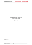
1
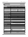
DES 410 & DES 411 Power Supply User’s Manual Purchase Record Please record all model numbers and serial numbers of your Magtrol equipment, along with the general purchase information. The model number and serial number can be found on either a silver identification plate or white label affixed to each unit. Refer to these numbers whenever you communicate with a Magtrol representative about this equipment. Model Number: _____________________________ Serial Number: _____________________________ Purchase Date: _____________________________ Purchased From: _____________________________ While every precaution has been exercised in the compilation of this document to ensure the accuracy of its contents, Magtrol assumes no responsibility for errors or omissions. Additionally, no liability is assumed for any damages that may result from the use of the information contained within this publication. Copyright Copyright ©2009 Magtrol, Inc. All rights reserved. Copying or reproduction of all or any part of the contents of this manual without the express permission of Magtrol is strictly prohibited. 1st Edition - revision A - February 2014 Safety Precautions 1. Make sure that all Magtrol dynamometers and electronic products are earth-grounded, to ensure personal safety and proper operation. 2. Check line voltage before operating electronic equipment. 3. Make sure that dynamometers and motors under test are equipped with appropriate safety guards. i Revisions To This Manual The contents of this manual are subject to change without prior notice. Should revisions be necessary, updates to all Magtrol User’s Manuals can be found at Magtrol’s web site at www.magtrol.com/support/manuals.htm. Please compare the date of this manual with the revision date on the web site, then refer to the manual’s Table of Revisions for any changes/updates that have been made since this edition. Revision Date 1st Edition - revision A - February 2014 Date Edition Changes Section 02/19/14 1st Edition - rev A Passing shielded cables into stuffing gland procedure added 2.6.2 02/19/14 1st Edition - rev A Figure 2-6 Update Stuffing gland view 2.6 02/19/14 1st Edition - rev A Notes about EMC stuffing gland was added 2.8, 2.9 02/19/14 1st Edition - rev A Figure 2-10 and 2-11 Update connecting drawing 2.8, 2.9 October 2013 First Edition English ii Table of Contents Safety Precautions........................................................................................................................i Revisions To This Manual..............................................................................................................ii Revision Date................................................................................................................................................................ii Table of Contents.........................................................................................................................iii Table of Figures....................................................................................................................................................... iv Preface............................................................................................................................................... v Purpose of This Manual........................................................................................................................................ v Who Should Use This Manual............................................................................................................................. v Manual Organization............................................................................................................................................ v Symbols used in this manual............................................................................................................................ vi 1. Introduction................................................................................................................................1 1.1General information....................................................................................................................................... 1 1.2 Data sheet............................................................................................................................................................... 2 2. Installation / Configuration.................................................................................................6 2.1GENERAL DESCRIPTION........................................................................................................................................ 6 2.2 DES 410 & DES 411 SAFETY WARNING................................................................................................................ 7 2.3 MOUNTING WITHOUT COOLING.......................................................................................................................... 7 2.4 MOUNTING WITH COOLING plate (Optional) ............................................................................................ 8 2.5 CONNECTION between THE VARIOUS UNITS.............................................................................................. 10 2.6 CONNECTING THE DES 410 and DES 411 Power Supply.......................................................................... 11 2.6.1 Passing Unshielded Cables Into Stuffing Gland.......................................................................................... 11 2.6.2 Passing Shielded Cables Into Stuffing Gland (with EMC stuffing gland)................................................... 12 2.7 CONFIGURATION OF THE DES 410 and DES 411 POWER SUPPLY.............................................................. 13 2.7.1 DES 410 Main Board : F1,F2, F3, SL12, SW1 & SW2 Location............................................................... 13 2.7.2 DES 411 Main Board: F1, F2, F3, SL12, SW1 & SW2 Location............................................................... 14 2.7.3 DES 410 & DES 411 CPLD Board : R39, R102, SL1 Location................................................................. 14 2.7.4 Main Board: F1, F2, F3, SL12, SL1, SL3, SW1 & SW3 Set-Up................................................................ 15 2.7.5 CPLD Board: R39, R102, SL1 Set-Up........................................................................................................ 15 2.7.6 Set-Up Values............................................................................................................................................... 15 2.8 CONNECTING THE DES 410 TO THE DSP 7000 CONTROLLER...................................................................... 16 2.9 CONNECTING THE DES 411 TO THE DSP 7000 CONTROLLER...................................................................... 17 3. Calibration.................................................................................................................................18 4. Repair............................................................................................................................................19 4.1 Repair...................................................................................................................................................................... 19 Service Information.....................................................................................................................20 Returning Magtrol equipment for Repair and/or Calibration.................................................... 20 Returning Equipment to Magtrol, Inc. (United States).............................................................................................. 20 Returning Equipment to Magtrol SA (Switzerland)................................................................................................... 20 iii Power supply unit Magtrol DES Table of contents Table of Figures 2. Installation / Configuration Figure 2–1 Dimensions of DES 410 and DES 411 case.............................................................................................6 Figure 2–2 DES 410 Power Supply mounted to the table of a test bench without cooling..........................................7 Figure 2–3 Cooling Plate (P/N 234-311-900-011)......................................................................................................8 Figure 2–4 DES 411 Power Supply with cooling plate mounted to the test bench table.............................................9 Figure 2–5 Connection between the various units in a test bench ...........................................................................10 Figure 2–6 Stuffing gland (Overview and separated)................................................................................................11 Figure 2–7 Connect Shiel of EMC Stuffing gland......................................................................................................12 Figure 2–8 Location of fuses F1, F2, F3; SolderLink SL12 & Contacts SW1, SW2 on the DES 410 circuit............13 Figure 2–9 Location of fuses F1, F2, F3; SolderLink SL12 & Contacts SW1, SW2 on the DES 411 circuit............14 Figure 2–10 Location of resistors R102, R39; SolderLink SL1 the DES 410 & DES 411 circuit.............................14 Figure 2–11 Connection of the DES 410 Power Supply to the Magtrol DSP 7000Controller...................................16 Figure 2–12 Connection of the DES 411 Power Supply to the Magtrol DSP 7000Controller...................................17 iv Preface Purpose of This Manual This manual has all the necessary information regarding the installation, connection and use of Magtrol's DES 410 and 411 Power Supply. To achieve maximum capability and ensure proper use of the system, please read this manual in its entirety before operating. Keep the manual in a safe place for quick reference whenever a question should arise. Who Should Use This Manual This manual is for users who want to install and use the Magtrol DES 410 and 411 Power Supply on a dynamometer test bench. The user should have suitable technical training in mechanics and electronics in order to install and use this load monitoring unit without risk. Manual Organization This section gives an overview of the structure of the manual and the information contained within it. Some information has been deliberately repeated in different sections of the document to minimize cross-referencing and to facilitate understanding through reiteration. Summary of the different chapters : Chapter 1: Introduction – Contains the technical data sheet for the DES 410 and DES 411 Power Supply and gives its technical characteristics as well as a brief overview of the application fields. Chapter 2: Installation / Configuration – Contains the mounting and configuration instructions for the DES 410 and DES 411 Power Supply, the dynamometer and the DSP7001 Programmable Controller. Chapter 3: Calibration – Provides instructions Chapter 4: REPAIR – Provides information on returning the unit to Magtrol for repair. v Preface Power supply unit Magtrol DES Symbols used in this manual The following symbols and type styles may be used in this manual to highlight certain parts of the text: Note: Caution: This is intended to draw the operator’s attention to complementary information or advice relating to the subject being treated. It introduces information enabling the correct and optimal function of the product. This is used to draw the operator’s attention to information, directives , procedures , etc . which , if ignored , may result in damage to the material being used . T he associated text describes the necessary precautions to take and the consequences that may arise if these precautions are ignored. WARNING! This introduces directives, procedures, precautionary measures, etc. which must be executed or followed with the utmost care and attention, otherwise the personal safety of the operator or third party may be at risk. The reader must absolutely take note of the accompanying text, and act upon it , before proceeding further. vi 1. Introduction 1.1 General information The Model DES 410 and 411 Power Supplies are designed for use with Magtrol's Eddy-Current and Powder Brake Dynamometers. The DES 410 and DES 411 supply the current to the coils of the brake within the dynamometer. They are controlled by an electronic peripheral, the Magtrol DSP7000 High Speed Programmable Controller. Note: The DES 41x is intended for use in an industrial environment and meets the standard IEC 61326-1 class B / Industrial electromagnetic environment. For the immunity test, a deflection +/-3% FSD and +/- 6%FSD is admitted for each performance criteria A and B 1 Chapter 1 – Introduction 1.2 DES 410/411 Power Supply Data sheet M AGTROL DES410 /DES411 Data Sheet DES 410 and DES 411 Power Supplies Features • • • • • • • • ForusewithMagtrolWBEddy-CurrentandPB PowderBrakeDynamometers Controlledcurrentsupply,withovervoltagefactor>5 Analoginputforcurrentset-point Selectionofnominalcurrent Controlbydigitalinputs/outputs Generalalarmprovidedbyrelay 2alarmoutputs(temperatureandelectricalcircuit) Availableineither115or230VAC DesCrIPtION DES410andDES411PowerSuppliesarespeciallydesigned for the full range of Magtrol’s Eddy-current and Powder brakedynamometerswiththedesigngoalprovidingthebest responsetime.TheDES410/DES411suppliesarepackaged inanindustrialhousingmadeofcastaluminum.Thisoffers superiorprotectionagainstradiatedemissionsinordertoavoid anydisruptionofthesurroundingelectronicsmodules.This housingmustbeinstalleddirectlyonthetestbench,nextto thebrake,ascloseaspossible. The DES 410 / DES 411 supplies can be controlled by digitalsignalsandanalogsetpointcomingfromperipheral electronics.TheDSP7000DynamometerControllerhasbeen designedtoworkwiththeDES41x. Control ThePowersupplycanbeswitchedONbyremotecontrol.The Stand-bysignalenablestheoutputcurrenttobedelivered.This excitationcurrentiscontrolledbyaset-pointinthe0-10VDC range.Thenominalvalueoftheexcitationcurrentissetby internalresistors.Therearetwodiscreteoutputsforalarms (opencollector).Thefirstisthe“TemperatureAlarm”.Itwill sYsteM CONFIGuratION Eddy-Current (WB) OR Powder Brake (PB) Dynamometer Speed indicateifthecoolingwateroftheDynamometerortheinner temperatureoftheDES41xareoutoflimits.Thesecondisthe ”ElectricalAlarm”.Itoccurswhenanovercurrentorashort circuitisdetected.Theoutputcurrentisimmediatelyturned OFFandlatchedwhiletheGeneralAlarmRelayissetunder itsAlarmposition.Alowstatefor200msoftheStand-by signalresetsthelatch. For applications with tandem dynanometers, the DES 410/DES 411 units also control the power supply of the electromagneticclutch. Supply Voltage ThemainsupplyvoltageoftheDES410/DES411isin the115/230VAC/50/60Hzrange.Noselectionisrequired. TheDES410powersupplyfeaturesagalvanicinsulation betweenthemaincircuitandthedynamometerpower. TheDES411doesnothavegalvanicseparation.Forsafety reasons,theDES41xcasehastobegroundedandtheuse ofagroundfaultcurrentcircuitbreakerisrecommended. This drawing illustrates a complete motor test system. A basic test stand can also be configured with just a WB/PB Dynamometer and the DES 41X Power Supply. TSC 401 Torque-Speed Conditioner GPIB or USB PC M-TEST Torque DES 41X POWER SUPPLY Excitation DSP7000 Dynamometer Controller www.magtrol.com 1 2 DES 410/411 Power Supply Chapter 1 – Introduction Specifications DES410 /DES411 ratINGs DES 410 DES 411 NETWORK SUPPLY Voltage 115 VAC / 230 VAC ±15 % Frequency Fuse 50 Hz / 60 Hz T1A or T2A depending on the brake(s)/ 115 VAC / 230 VAC T2A to T12A depending on the brake(s)/ 115 VAC / 230 VAC 1 A + clutch 3 A + clutch / 230 VAC 6 A + clutch / 115 VAC Maximum current ELECTROMAGNETIC CLUTCH SUPPLY Voltage 115 VAC / 230 VAC Current 1A SUPPLY FOR EXTERNAL USE Voltage 12 VDC ±5 % Maximum Current 300 mA SELECTION OF NOMINAL CURRENT (Selected by resistors) 0.5 A; 1.0 A; 1.5 A; 2.0 A 2.5 A; 4.0 A; 5.0 A; 7.5 A; 10.0 A; 12.0 A EXCITATION SET-POINT Voltage 0 to 10 VDC Impedance > 50 kΩ DIGITAL INPUTS (GALVANICALLY INSULATED) Remote Control of the Network Input (PSC) Relay coil +24 VDC / 11 mA Control of the Electromagnetic Clutch Stand-by (enable) Optocoupler activated by +24 VDC / 2.5 mA Optocoupler activated by either +24 VDC or +12VDC / 2.5 mA max DIGITAL OUTPUTS (GALVANICALLY INSULATED) Temperature Alarms 2 open collector outputs: Umax = 40 VDC, Imax = 3 mA Electrical Alarm GENERAL ALARM Relay Contact 2 A / 30 VDC ENVIRONMENTAL CHARACTERISTICS Operating Temperature 0°C to +50°C Storage Temperature -20°C to +70°C Humidity 0 to 90% as per DIN 40040 Protection Class Assembly IP 66 The housing must be electrically and thermally coupled to the metal frame of the test bench to allow heat dissipation. MECHANICAL CHARACTERISTICS Housing Extruded cast aluminium Weight (without cable) 5.2 kg; 11.5 lb Weight (with integrated cable) 6.2 kg; 13.7 lb 2 3 M AGTROL Chapter 1 – Introduction DES 410/411 Power Supply Specifications DES410 /DES411 DIMeNsIONs DES 411 Water Cooling System (For all 15 series Dynamometers except 1 WB 15 and 1 PB 15) K M DES 411 Q J FRONT VIEW H Mounting Screw M6×30 FRONT VIEW D F C P E B A OVERHEAD VIEW NOTE: Original dimensions are in Metric units. Dimensions converted to English units have been rounded up to 2 decimal places. A B C D E F H J K M mm 287 272 190 175 ≈17 ≈219 12 10 90 30 in 11.30 10.71 7.48 6.89 0.63 8.58 0.47 0.39 3.54 1.06 N OVERHEAD VIEW mm in N P 200 290 7.87 11.42 Q 15 0.59 TheDES410/DES411suppliesaredeliveredwithintegratedcables(includingconnectors)withalengthof1.5meters onthedynamometerconnectionsideand5metersonthecontrollerside.TheDES410/DES411unitsaretobemounted onametallicsurfaceinordertoallowampleheatdissipation.Forsafetyreasons,theDES41xcasehastobegrounded. For2-3-4WB15and2-4PB15dynamometers,theDES411/12xPowerSupplywithintegratedWaterCoolingSystem (seeabovedrawing)shouldbeused. 3 4 M AGTROL DES 410/411 Power Supply Chapter 1 – Introduction Specifications DES410 /DES411 BlOCk DIaGraM Feedback Current Selection of Nominal Current Excitation Circuit Primary Supply Circuit Excitation Current Control Excitation Control Electrical Alarm Excitation Temp. Control Interface Differential Dynamometer Temp. Clutch Control Control Inputs/Outputs Fuse Network Filter +12 VDC Excitation Current Temperature Alarm Clutch Electrical Alarm Stand-by Excitation Set-point Primary Supply Control General Alarm Control Input Clutch Supply Inputs/Outputs OPtIONs aND OrDerING INFOrMatION IftheDESisorderedseparately(fromthedynamometer),itisabsolutelynecessarytospecifywhichmodelofEddy-current/ powderbrakewillbeusedwiththeDESpowersupplyinordertolimittheoperatingcurrentandpreventpossibledamageto thedynamometerbrake.Mainsvoltage(115VACor230VAC)shouldalsobedefinedwhenordering. DESCRIPTION MODEL PART NUMBER Power Supply for WB/PB 2.7 and 43 Dynamometers DES 410/11x 234-410-000-11x Power Supply for WB/PB 65, 115, 1 PB 15 and 1 WB 15 Dynamometers DES 411/11x 234-411-000-11x Power Supply with Water Cooling Plate for 2, 3, 4 WB 15 and 4 PB 15 Dynamometers DES 411/12x 234-411-000-12x NOTE: AllDES41XPowerSuppliesincludethecorrespondingdynamometerconnectioncables.Thelastdigitofthepart Numberreferstothecablelenghtinaccordancewiththefollowingtable. 4 LAST DIGIT X CABLE LENGTH DYNAMOMETER SIDE CABLE LENGTH CONTROLLER SIDE 1 1.5 m 5m 2 1.5 m 10 m 3 1.5 m 20 m 4 2.5 m 5m 5 2.5 m 10 m 6 2.5 m 20 m 5 M AGTROL 2. Installation / Configuration 2.1 GENERAL DESCRIPTION The housing of the power supply must be electrically and thermally connected to the metal frame of the test bench to allow heat dissipation. The test bench as well as it's structure must be connected to earth (ground). For safety reasons, the DES 41x case has to be grounded and the use of a ground fault current circuit breaker is recommended. The dimensions necessary for mounting the housing of the power supply are provided in Figure 1. The data sheet provides all other dimensions necessary for the installation of the power supply. The housing of the DES 410 and DES 411 has four holes for mounting and includes the necessary four M6 × 30 hexagon socket head fixing screws. To reach the mounting holes, it is necessary to remove six screws from the cover of the power supply. Once the unit is installed and calibrated, for safety reasons, it is necessary to replace and secure the cover of the power supply. The cover has to be mounted with the Yellow warnings placed as shown. Figure 2–1 Dimensions of DES 410 and DES 411 case 6 DES 410/411 Power Supply 2.2 DES 410 & DES 411 SAFETY WARNING 2.3 Chapter 2 – Installation / Configuration WARNING! THE DES 41x POWER SUPPLY MUST ALWAYS be grounded. Make sure the DES 41x is turned off and disconnected from the controller for 3 minutes before removing the housing cover. THE USER OR a third party COULD BE SERIOUSLY or EVEN fatally injured IF These warnings are ignored. THE USE OF A 6A/30mA GROUND FAULT CIRCUIT BREAKER IS RECOMMENDED MOUNTING WITHOUT COOLING For any DES 410 and for DES 411 Power Supply providing an excitation current up to 5A included (dynamometer models 1WB/PB 65, 2WB/PB 65, 1WB/PB 115, 2WB/PB 115 and 1WB/PB 15), a cooling plate is not required The power supply can be mounted on a support fixed to the table or directly to the test bench. An example of such mounting is given in Figure 2-2 Test bench DES41x Power Supply Metallic case support Figure 2–2 DES 410 Power Supply mounted to the table of a test bench without cooling 7 Chapter 2 – Installation / Configuration 2.4 DES 410/411 Power Supply MOUNTING WITH COOLING plate (Optional) For a DES 411 Power Supply providing an excitation current higher than 5 A (dynamometer models 2 WB/PB 15 and larger), a cooling plate is required. Magtrol recommends the use of the Cooling Plate , P/N: 234-311-900-011. (see Figure 2-3). Another solution is to mount the DES 411 on a metal plate having a minimal dimensions of 500 mm × 500 mm × 2 mm. It is necessary to mill holes in the plate for the feet of the unit in order to get a good thermal contact using heat sink compound to improve the thermal coupling. This plate can then be mounted to the test bench table. In both cases, with the power supply fixed to the cooling plate, it is recommended to attach the plate to the test bench. An example of assembly is given in Figure 2-4. The water flow through the cooling plate must be equal to 30 l/h. The differencial pressure should not be less than 0.05 bar. Furthermore, the absolute pressure at the inlet should not exceed 1.5 bar. Figure 2–3 Cooling Plate (P/N 234-311-900-011) 8 DES 410/411 Power Supply Chapter 2 – Installation / Configuration Test bench DES41x Power Supply Cooling plate Metallic case support Figure 2–4 DES 411 Power Supply with cooling plate mounted to the test bench table 9 Chapter 2 – Installation / Configuration 2.5 DES 410/411 Power Supply CONNECTION between THE VARIOUS UNITS A test bench includes not only the dynamometer, but also a TSC 401 Torque/Speed Conditioner and DES Series Power Supply. The test bench is controlled by a DSP 7000 Programmable Controller. Figure 2-5 shows the connection between the various units in a test bench. WB or PB Dynamometer TSC 401 Torque/Speed Conditioner DES 410/411 Power Supply DSP7000 High Speed Programmable Controller Figure 2–5 Connection between the various units in a test bench Note: The DES 410/411 is fully compatible with the DSP 6001 Programmable controler 10 DES 410/411 Power Supply 2.6 Chapter 2 – Installation / Configuration CONNECTING THE DES 410 and DES 411 Power Supply The DES 410 and DES 411 Power Supplies are sold as a kit, with the cables already connected. The DES 410 and DES 411 Power Supplies are equipped with a stuffing gland which allows cables to pass through the wall of the housing of the unit while maintaining the seal of the housing and holding the cables. 2.6.1 Passing Unshielded Cables Into Stuffing Gland 1. Strip the conductors from the various cables. 2. Remove the lid of the power supply housing by unscrewing its six screws. 3. Pass the cables into the stuffing gland by proceeding as follows (see Figure 2-6): a. Unscrew element Counterclockwise. Element must not be removed from the housing. b. Remove joints and from element . These two elements allow the stuffing gland to adapt to various diameters of cable. Element Can be removed from element by simply pushing it outwards. c. Pass the cables through elements , (if used), and . d. Reassemble the elements of the stuffing gland and, before replacing element , lubricate the seal with silicone as indicated in Figure 2-6. Tighten element so that it projects beyond joints and/or to provide the degree of seal required. 4. Connect the conductors of the various cables to the terminals of the power supply unit. 5. Replace the cover of the power supply housing and tighten its six screws. Caution : Do not damage the seals with sharp edged objects. check that no foreign body can slide between the elements of the stuffing gland. de-grease the surface of the cable that will come in contact with the seal. the stuffing gland seal cannot be guaranteed if these instructions are not followed. Stuffing gland mounted Overflowing of the joint Cable Top Internal joint External joint Grease the frontal part only Down Figure 2–6 Stuffing gland (Overview and separated) 11 Chapter 2 – Installation / Configuration 2.6.2 DES 410/411 Power Supply Passing Shielded Cables Into Stuffing Gland (with EMC stuffing gland) For ER 405, EH 147 and EN 104 cables (see drawings, paragraphe 2.8 and 2.9), EMC type stuffing gland are used. 1. Strip the conductors from the various cables. 2. Remove the lid of the power supply housing by unscrewing its six screws. 3. Pass the cables into the stuffing gland by proceeding as follows (see Figure 2-6): a. Unscrew element Counterclockwise. Element must not be removed from the housing. b. Remove joints and from element . These two elements allow the stuffing gland to adapt to various diameters of cable. Element Can be removed from element by simply pushing it outwards. c. Pass the cables through elements , (if used), . d. Strip the cable (outer sheath) to the elements output and cut the shield over 5-8 mm as show in Figure 2-7. Pass the stripped cable through the element . e. Connect the shield on the metallic part of element as show in Figure 2-7. f. Reassemble the elements of the stuffing gland (take care that the shield remains in place) and, before replacing element , lubricate the seal with silicone as indicated in Figure 2-6. Tighten element so that it projects beyond joints and/or to provide the degree of seal required. 4. Connect the conductors of the various cables to the terminals of the power supply unit. 5. Replace the cover of the power supply housing and tighten its six screws. Caution : Do not damage the seals with sharp edged objects. check that no foreign body can slide between the elements of the stuffing gland. de-grease the surface of the cable that will come in contact with the seal. the stuffing gland seal cannot be guaranteed if these instructions are not followed. Figure 2–7 Connect Shiel of EMC Stuffing gland 12 DES 410/411 Power Supply 2.7 Chapter 2 – Installation / Configuration CONFIGURATION OF THE DES 410 and DES 411 POWER SUPPLY The configuration of the DES 410 and DES 411 Power Supply requires a selection of fuses, resistors and SolderLink in accordance with the dynamometer model and the Main supply voltage. 2.7.1 DES 410 Main Board : F1,F2, F3, SL12, SW1 & SW2 Location The contacts SW1 and SW2 must be left Open to allow the DSP7000 to control the primary supply circuit. F3 : 2 A/250 V/5x20 SL12 SW1 & SW2 SL1 SL3 F1 & F2 Figure 2–8 Location of fuses F1, F2, F3; SolderLink SL12 & Contacts SW1, SW2 on the DES 410 circuit 13 Chapter 2 – Installation / Configuration 2.7.2 DES 410/411 Power Supply DES 411 Main Board: F1, F2, F3, SL12, SW1 & SW2 Location The contacts SW1 and SW2 must be left Open to allow the DSP7000 to control the primary supply circuit. SW1 & SW2 F3 : 2 A/250 V/5x20 SL1 SL12 SL3 F1 & F2 Figure 2–9 Location of fuses F1, F2, F3; SolderLink SL12 & Contacts SW1, SW2 on the DES 411 circuit 2.7.3 DES 410 & DES 411 CPLD Board : R39, R102, SL1 Location Figure 2–10 Location of resistors R102, R39; SolderLink SL1 the DES 410 & DES 411 circuit 14 DES 410/411 Power Supply Chapter 2 – Installation / Configuration 2.7.4 Main Board: F1, F2, F3, SL12, SL1, SL3, SW1 & SW3 Set-Up • SL12: solder link is done for 230VAC only. • SL1 & SL3: DES 411 only. They are to be done only for the xWB/PB15 under 100 - 115VAC. • F3: 2AT/250V/5x20. Whatever the main supply voltage. • The contact SW1 and SW2 must be let Open to allow the DSP7000 to control the primary supply circuit. • F1=F2: xxAT/250V/ 6.3x32 in accordance with Table 1 2.7.5 CPLD Board: R39, R102, SL1 Set-Up • R39 & R102 in accordance with Table 1 • SL1: Solder Link always Open unless otherwise stated. 2.7.6 Set-Up Values Dynamometer WB/PB DES 41x Type lex [A] 1WB/PB2.7-8-K 410 0.5 2WB/PB2.7-8-K 410 1 3PB2.7-8-K 410 1.5 4WB/PB2.7-8-K 410 1WB/PB43 410 2WB/PB43 1WBPB65 R102 [Ohm] 115 V AC F1, F2 230 V AC F1, F2 348 none T2A T1A 1.21K 90.9K T2A T1A 2.15K 36.5K T2A T2A 2 3.16K 21.5K T2A T2A 1 1.21K 90.9K T2A T1A 410 2 3.16K 21.5K T2A T2A 411 2.5 499 none T4A T2A 2WB/PB65 411 5 1.54K 57.6K T8A T4A 1WB/PB115 411 2.5 499 none T4A T2A 2WB/PB115 411 5 1.54K 57.6K T8A T4A 1WB/PB15 411 4 1.1K 100K T8A T4A 2WB/PB15 411 7.5 2.61K 26.1K T12A T8A 3WB15 411 10 3.83K 15.8K T12A T8A 4WB/PB15 411 12 4.64 11.5K T12A T8A Caution: Make R39 [Ohm] sure the fuse value is correct. The unit is no longer protected when the value of one or all of the fuses is too high. However, the fuses are likely to blow prematurely if their value is not sufficient. 15 Chapter 2 – Installation / Configuration CONNECTING THE DES 410 TO THE DSP 7000 CONTROLLER Earth ground Terminal group P3 Terminal group P2 5 4 3 2 1 Shield Excitation + Excitation + Excitation Excitation Dynamometer B temp. Dynamometer A temp. 7 6 5 4 3 2 1 Main alarm “OFF” Main alarm Main alarm “ON” 0V +12 V 5 4 3 2 1 Stand-by Temperature alarm Coupling Electronic alarm Water Flow N/C Primary supply control 0 V-DSP Shield Shield 12 11 10 9 8 7 6 5 4 3 2 1 Water Flow_H Water Flow_C J9 2 1 Current Set Point_C Current Set Point_H Terminal group P1 Terminal group P0 Main supply brown blue Transformer yellow/green red EH 147 blue green white Alarm switch N/C ER 405 green white brown yellow black grey pink red blue DSP 7000 Controller Terminal group P4 Neutral AC Phase AC Phase Coupling Neutral Coupling Earth ground Electromagnetic Coupling 2.8 DES 410/411 Power Supply Water Flow Switch (Optional) Bornier_2 Figure 2–11 Connection of the DES 410 Power Supply to the Magtrol DSP 7000Controller. Note: For EH 147 and ER 405 cables, using EMC type stuffing gland, ensure cable shield makes good contact with the aluminium housing. 16 DES 410/411 Power Supply CONNECTING THE DES 411 TO THE DSP 7000 CONTROLLER Earth Ground Terminal Group P4 Terminal group P3 Neutral AC Phase AC Phase Coupling Neutral Coupling Earth Ground 5 4 3 2 1 Shield Excitation + 7 6 5 4 3 2 1 Excitation + Excitation Excitation Dynamometer B Temp. Dynamometer A Temp. Main Supply brown blue Transformer yellow/green 6 Electromagnetic Coupling EN 104 5 D A B C 4 3 2 1 black Terminal group P2 Main alarm “OFF” Main alarm Main alarm “ON” 0V +12 V Stand-by Temperature alarm Coupling Electronic alarm Water Flow N/C Primary supply control 0 V-DSP Shield Shield 12 11 10 9 8 7 6 5 4 3 2 1 Water Flow_H Water Flow_C J9 2 1 Current Set Point_C Current Set Point_H Terminal group P1 5 4 3 2 1 Terminal group P0 Alarm switch N/C ER 405 green white brown yellow black grey pink red blue DSP 7000 Controller 2.9 Chapter 2 – Installation / Configuration Water Flow Switch (Optional) Bornier_2 Figure 2–12 Connection of the DES 411 Power Supply to the Magtrol DSP 7000Controller. Note: For EN 104 and ER 405 cables, using EMC type stuffing gland, ensure cable shield makes good contact with the aluminium housing. 17 3. Calibration When the DES 410 or 411 Power Supply is purchased as part of a complete motor test system it is calibrated by Magtrol according to the dynamometer with which it will be used. Calibration requires specific tools. If you are facing a calibration need, please contact our after sales service at: Magtrol Inc. 70 Gardenville Parkway Buffalo, NY 14224 Attn: Repair Department. E-mail : [email protected] Magtrol SA After Sales Service Route de Montena 77 1728 Rossens / Fribourg Switzerland E-mail : [email protected] 18 4. Repair 4.1 Repair In case of a defect, please refer to the warranty information at the back of this manual. Whether you are directed to ship your equipment to Magtrol. Inc. in the United States or Magtrol SA in Switzerland, it is very important to include the following information with your return shipment: • Model number, part number, serial number, order number and date of acquisition • Description of the defect and the conditions in which it appeared • Description of the test bench (drawing, photographs, sketches, etc.) • Description of the tested object (drawing, photographs, sketches, etc.) • Description of the test cycle To allow Magtrol to complete the work in the best possible time, carefully pack the power supply and follow the procedure outlined here when returning your equipment for repair. • Pack carefully the power supply unit • Join the report of imperfection indicating the problems Note : Do not hesitate to contact the Magtrol sales department for further information. 19 Service Information Returning Magtrol equipment for Repair and/or Calibration Before returning equipment to Magtrol for repair and/or calibration, please visit Magtrol’s Web site at http://www.magtrol.com/support/rma.htm to begin the Return Material Authorization (RMA) process. Depending on where the equipment is located and which unit(s) will be returned, you will be directed to either ship your equipment back to Magtrol, Inc. in the United States or Magtrol SA in Switzerland. Returning Equipment to Magtrol, Inc. (United States) When returning equipment to Magtrol, Inc.’s factory in the United States for repair and/or calibration, a completed Return Material Authorization (RMA) form is required. 1.Visit Magtrol’s Web site at http://www.magtrol.com/support/rma.htm to begin the RMA process. 2. Complete the RMA form online and submit. 3. An RMA number will be issued to you via e-mail. Include this number on all return documentation. 4. Ship your equipment to: Magtrol, Inc. 70 Gardenville Parkway Buffalo, NY 14224 Attn: Repair Department 5. After Magtrol’s Repair Department receives and analyzes your equipment, a quotation listing all the necessary parts and labor costs, if any, will be faxed or e-mailed to you. 6. After receiving your repair estimate, provide Magtrol with a P.O. number as soon as possible. A purchase order confirming the cost quoted is required before your equipment can be returned. Returning Equipment to Magtrol SA (Switzerland) If you are directed to ship your equipment to Switzerland, no RMA form/number is required. Just send your equipment directly to Magtrol SA in Switzerland and follow these shipment instructions: 1. Ship your equipment to: Magtrol SA After Sales Service Route de Montena 77 1728 Rossens / Fribourg Switzerland VAT No: 485 572 2. Please use our forwarder : TNT • 1-800-558-5555 • Account No 154033 Only ship ECONOMIC way (3 days max. within Europe) 3. Include the following documents with your equipment: • Delivery note with Magtrol SA’s address (as listed above) • Three pro forma invoices with: •Your VAT number •Value - for customs purposes only • Description of returned goods •Origin of the goods (in general, Switzerland) • Noticed failures 4. A cost estimate for repair will be sent to you as soon as the goods have been analyzed. If the repair charges do not exceed 25% the price of a new unit, the repair or calibration will be completed without requiring prior customer authorization. 20 Testing, Measurement and Control of Torque-Speed-Power • Load-Force-Weight • Tension • Displacement Magtrol Inc 70 Gardenville Parkway Buffalo, New York 14224 USA Phone: +1 716 668 5555 Fax: +1 716 668 8705 E-mail: [email protected] Magtrol SA Route de Montena 77 1728 Rossens / Fribourg, Switzerland Phone: +41 (0)26 407 3000 Fax: +41 (0)26 407 3001 E-mail: [email protected] www.magtrol.com Subsidiaries in: Germany • France China • India Worldwide Network of Sales Agents