1
IK 5000
Connections to the IK 5000 are made via
its D-sub connectors. Depending on the
version, further connections are made
through one, t wo or three additional slot
covers. Please order the adapter cables
necessary bet ween the individual
components separately.
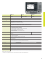
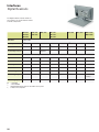
Slots1)
IK 5293
IK 5294
IK 5394-EG IK 5394-3D IK 5493
IK 5494-2D IK 5494-3D IK 5594
2
2
3
4
3
4
4
4
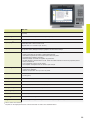
Location
Encoders for
X, Y, Z
IK
1 VPP or TTL
CNC outputs
IK
–
–
–
–
!
!
!
!
Foot switch
IK
!
!
!
!
!
!
!
!
Fiber-optic cable
Slot L
–
–
!2)
–
!2)
–
–
–
Touch probe3)
Slot 1
!
–
–
!
–
–
!
TP 200
Light control
Slot 1
–
–
–
!
–
!
!
!
Encoder for Q
Slot 2
–
1 VPP or TTL
Zoom
Slot 3
–
–
–
!
–
!
!
!
Video
PC
–
–
–
USB
4)
camera
–
USB
camera4)
USB
camera4)
USB
camera4)
! = Standard; – = Not available
1)
Including IK; 2) Connected directly to the IK PCB, special slot cover with cable guide included in delivery
3)
HEIDENHAIN touch probe or Renishaw touch probe; 4) Connected to the USB port of the PC
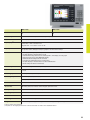
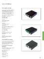
Adapter cables
Complete with D-sub connector (female),
15-pin (1 VPP) or 9-pin (TTL), and 3-pin
mini-DIN connector (female)
1 VPP
TTL
For 3 axes XYZ and foot switch
540 550-40
540 550-10
For 2 axes XY and foot switch
540 540-24
540 540-05
540 541-24
540 541-05
(6;
For connecting the XYZ encoders and
the foot switch to the IK 5000
"%(&66;
Complete with D-sub connector (female),
15-pin (1 VPP) or 9-pin (TTL)
(6;
For connecting the Q encoder to the
IK 5000
29