1
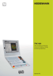
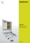
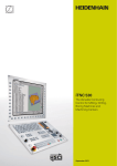
TNC 320
The Compact Contouring
Control for Milling, Drilling
and Boring Machines
September 2012
This brochure describes the functions
and specifications of the TNC 320 with
NC software 34055x-06.
2
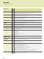
Contents
The TNC 320...
Where can it be used?
4
Compact and versatile
– The right control for milling, drilling and boring machines
How does it look?
6
Well designed and user friendly
– The TNC 320 in dialog with the user
What can it do?
8
Minimize setup and nonmachining time
– The TNC 320 makes setup easy
– The TNC 320 manages and measures
12
Machining with four axes
– Swivel head and rotary table controlled by the TNC
How is it programmed?
14
Programming, editing, testing
– The TNC 320 opens endless possibilities
– Graphic support in any situation
16
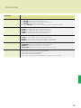
Programming in the workshop
–
–
–
–
–
Straightforward function keys for complex contours
Programming contours unconventionally
Field-proven cycles for recurring operations
Reusing programmed contour elements
Fast availability of all information
22
Open for communication
– Fast data transfer with the TNC 320
– TNC 320 programming station
Are there any accessories?
24
Workpiece measurement
– Setup, presetting and measuring with touch trigger probes
25
Tool measurement
– Measuring length, radius and wear right on the machine
26
Positioning with the electronic handwheel
– Delicate axis traverse
... At a glance
27
Overview
–
–
–
–
Specifications
User functions
Options
Accessories
3
Compact and versatile
– The right control for milling, drilling and boring machines
For more than 30 years, TNC controls from
HEIDENHAIN have been proving
themselves in daily use on milling, drilling
and boring machines, and machining
centers. While the controls have undergone
continuous development during this period,
the basic operational technique has
remained the same.
Shop-oriented programming
You program conventional milling and
drilling operations yourself at the machine,
in plain language dialog—the workshoporiented programming language from
HEIDENHAIN. The TNC 320 provides you
with optimum support with practical
prompts, questions and graphical aids.
You will find these principles implemented
in the TNC 320 as well: shop-oriented
programmability with graphic support,
many field-proven cycles and an operational
design familiar from other HEIDENHAIN
controls.
Standard operations and even complex
applications are on call as a large variety of
real-world machining cycles or coordinate
transformations.
4
Simple operation
For simple work, such as face milling, you
need not write a program on the TNC 320.
It is just as easy to operate the machine
manually by pressing the axis keys or—for
maximum sensitivity—using the electronic
handwheel.
Offline program creation
The TNC 320 can be programmed remotely
just as well. Its Fast Ethernet interface
guarantees very short transfer times, even
of long programs.
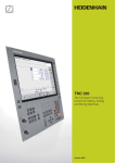
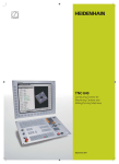
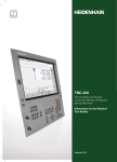
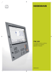
The TNC 320 is compact and easy to
read.
The TNC 320 is a compact but versatile
contouring control for three servo axes and
servo spindle. A further servo axis is an
option. Thanks to its flexible operation—
workshop-oriented programmability with
HEIDENHAIN conversational programming
or offline programming—and its scope of
features, it is especially suited for use on
universal milling, drilling and boring
machines for the following:
• Series and single-part production
• Tool making
• Machine building
• Research and development
• Prototypes and pilot plants
• Repair departments
• Training and education facilities
It also offers the applicable features both
necessary and helpful for:
Universal milling machines
• Free contour programming
• Milling cycles for complex contours
• Fast presetting with HEIDENHAIN touch
probes
Drilling and boring machines
• Cycles for drilling, boring and spindle
alignment
• Cycles for Cartesian and polar point
patterns
• Drilling oblique holes
Machines with parallel secondary axes
• Compensating movement in the
secondary axis U, V, W through the
principal axis X, Y, Z
• Defining the principal and secondary
axes in the NC program makes it
possible to run programs on different
machine configurations
• Including movements of parallel axes in
the position display of the associated
principal axis (sum display)
5
Well designed and user friendly
– The TNC 320 in dialog with the user
The screen
The 15-inch TFT color flat-panel display
shows a clear overview of all relevant
information for programming, operating
and inspecting the machine tool and
control, such as program blocks, comments
and error messages. More information is
provided through graphic support during
program entry, test run and actual
machining.
The selectable “split screen” display
shows the part program blocks in one half
of the screen and the graphics or the
status display in the other half.
During the course of the program, status
displays will always offer information on
tool position, the current program, active
cycles and coordinate transformations, and
other data. The TNC 320 even shows the
current machining time.
The keyboard
As with all TNCs from HEIDENHAIN, the
keyboard is tailored to the programming
process. The well thought-out configuration
of keys facilitates program input. Simple
words and abbreviations or unambiguous
symbols clearly indicate each key’s function.
Certain functions of the TNC 320 are
available by soft key.
6
Keys on the monitor
Select the screen layout
Display machine mode or
programming mode
Unambiguous keys make
programming easy.
Soft keys for selecting
functions in screen
Shift between soft-key rows
Keys on the control panel
Program/file management, TNC functions
Programming modes
Program management:
Manipulate and delete programs
Programming and Editing
Supplementary operating modes
Test Run with graphic simulation
Help function
Straight line, chamfer
Display error messages
Circular arc with center point
Show pocket calculator
Circular path with known radius
Machine operating modes
Manual Operation
Circular arc with tangential
connection
Corner rounding
Electronic Handwheel
Contour approach and departure
Positioning with Manual Data Input
Free contour programming
Program Run, Single Block
Enter polar coordinates
Program Run, Full Sequence
Enter incremental dimensions
Navigation and input
Many functions are entered by
soft key.
With the gray path function keys
and conversational guidance, you
program line segments and
circular arcs defined in various
ways.
Enter a parameter instead of a fixed
numerical value/Define parameters
Transfer actual position to program
Definition and calling of tools
Definition and calling of cycles
Navigation in dialogs
Delete the last entered character
Labeling and calling of subroutines
and program repeats
Spindle speed and feed rate are
easily adjusted.
Programmable program call
Programmed stop, interrupt/
discontinue
Touch probe functions
Special functions,
e.g. comments, structure
7
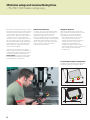
Minimize setup and nonmachining time
– The TNC 320 makes setup easy
Before you can begin machining, you must
first clamp the tool and set up the machine,
find the position and orient the workpiece
on the machine, and set the workpiece
reference point. Without support from the
control this is often a time-consuming
procedure, but it is indispensable. After all,
any error directly reduces the machining
accuracy. Particularly in small and mediumsized production runs, as well as for very
large workpieces, setup times become
quite a significant factor.
Here the TNC 320 shows its strengths:
With its practice-oriented setup features it
supports the operator and helps to reduce
non-machining time. Together with the
touch probes, the TNC 320 offers various
probing features for aligning, presetting,
and measuring the workpieces.
Delicate manual traverse
For setup, you can use the direction keys
to move the machine axes manually or in
incremental jog. A simpler and more
reliable way, however, is to use the
electronic handwheels from HEIDENHAIN
(see page 26). Particularly with the portable
handwheels you are always close to the
action, enjoy a close-up view of the setup
process, and can control the infeed
responsively and precisely.
Workpiece alignment
With HEIDENHAIN touch probes (see
page 24) and the probing functions of the
TNC 320, you can forgo any tedious
manual alignment of the workpiece:
• Clamp the workpiece in any position.
• The touch probe ascertains the
workpiece misalignment by probing a
surface, two holes, or two studs.
• The TNC 320 compensates the
misalignment with a “basic rotation,”
which means that in the NC program the
part is rotated by the measured
misalignment.
Compensating workpiece misalignment
Compensate misalignment by rotating the
coordinate system or turning the table
8
Workpiece presetting
You can use a reference point to assign a
defined value in the TNC display to any
workpiece position. Finding this point
quickly and reliably reduces nonproductive
time and increases machining accuracy.
Datum management
The datum management makes flexible
machining, shorter setup times and
increased productivity possible. In other
words, it makes it much easier to set up
the machine.
The TNC 320 features probing cycles for
automatic presetting. Once found, you can
save these reference points
• in the datum management
• in a datum table, or
• by directly setting the displayed value.
In the datum management you can save
any number of datums and assign an
individual basic rotation to each one.
There are three ways to save datums
rapidly in the datum management:
• In the Manual mode by soft key
• By using the probing functions
• With the automatic probing cycles
Workpiece presetting
At a corner, for example, or in the center of
a circular stud
9
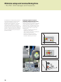
Minimize setup and nonmachining time
– The TNC 320 manages and measures
The difference in requirements placed on
the classical machine for tool and moldmaking and machining centers are
becoming ever less distinct. Of course,
the TNC 320 is capable of controlling
automated manufacturing processes. It
has the functions required to manage and
measure tools and inspect the machining
process. It helps you reduce non-cutting
time, increase productivity and improve
production quality.
Inspecting workpieces for proper
machining and dimensional accuracy
The TNC 320 features a number of
measuring cycles for checking the geometry
of the machined workpieces. To run the
measuring cycles, you simply insert a touch
probe from HEIDENHAIN (see page 24)
into the spindle in place of a tool. This
enables you to
• recognize a workpiece and call the
appropriate part program,
• check whether all machining operations
were conducted correctly,
• determine infeeds for finishing,
• detect and compensate tool wear,
• ascertain machining error trends.
Length measurement
Circular pocket/hole measurement
Measuring the angle of a plane
10
Tool measurement and automatic
compensation of tool data
Together with the TT and TL touch probes
for tool measurement (see page 25) the
TNC 320 can automatically measure tools
while they are in the machine. The TNC 320
saves the ascertained values of tool length
and radius in the central tool file. By
inspecting the tool during machining you
can quickly and directly measure wear or
breakage to prevent scrap or rework. If the
measured deviations lie outside the
tolerances, or if the monitored life of the
tool is exceeded, the TNC 320 locks the
tool and automatically inserts a
replacement tool.
Tool management
For machining centers with automatic tool
changers, the TNC 320 offers a central tool
memory for any number of tools. The tool
memory is a freely configurable file and
can therefore be optimally fitted to your
needs. You can even have the TNC 320
manage your tool names. The control
prepares the next tool change while the
current tool is still cutting. This significantly
reduces the non-cutting time required for
changing tools.
Measuring the tool radius
Measuring the tool length
Measuring tool wear
11
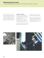
Machining with four axes
– Swivel head and rotary table controlled by the TNC (option)
Many five-axis operations that at first
glance may seem very complex can be
reduced to conventional 2-D movements
that are simply tilted about one or more
rotary axes or wrapped onto a cylindrical
surface. The TNC supports you with
application-oriented functions to help you
write and edit such programs quickly and
simply without a CAD/CAM system.
Tilting the working plane*
Programs for contours and holes on
inclined surfaces are often very complex
and require time-consuming computing
and programming work. Here the TNC 320
helps you to save a great deal of
programming time.
You program the part as usual in the
working plane (e.g. the X/Y plane), but it is
machined in a plane that is rotated in one
or more axes about the main plane.
The PLANE feature makes it easy to define
a tilted working plane: You can specify tilted
working planes in seven different ways,
12
depending on the information on the
workpiece drawing. Clearly arranged
support graphics assist you during input.
You can also use the PLANE function to
define the positioning behavior for tilting so
that there are no unpleasant surprises
when the program is run. The settings for
defining the positioning behavior are
identical for all PLANE functions, making
everything that much easier.
Machining cylindrical surfaces*
With the TNC 320 it is quite easy to
program contours (which consist of straight
lines and arcs) on cylindrical surfaces using
rotary and tilting tables: You simply
program the contour in a plane as if the
cylinder surface were unrolled. The
TNC 320 then executes the operation on
the surface of the cylinder.
The TNC 320 features three cycles for
cylindrical surface machining:
• Slot milling (the slot width is the same as
the tool diameter)
• Guide-groove milling (the slot width is
greater than the tool diameter)
• Ridge milling
* The machine must be prepared by the machine tool
builder for this function.
13
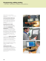
Programming, editing, testing
– The TNC 320 opens endless possibilities
The TNC 320 is just as universal in
application as it is flexible in machining and
programming.
Positioning with Manual Data Input
You can start working with the TNC 320
even before writing a complete part
program. Simply machine a part step by
step—switching as you want between
manual operation and automatic
positioning.
Programming at the machine
HEIDENHAIN controls are workshop
oriented, which means that they were
conceived for programming right at the
machine. With conversational
programming you can forget about
memorizing G codes. Instead you use
dedicated keys and soft keys to program
line segments, circular arcs and cycles.
With a keystroke, you initiate a HEIDENHAIN
plain language dialog, and the TNC begins
immediately to support you actively in your
work. Unambiguous questions and
prompts help you enter all the required
information.
If you are used to DIN/ISO programming,
however, the TNC 320 is still the right
control for you. It displays soft-key rows
dedicated to the most important DIN/ISO
commands. Or you connect a USB
keyboard and use it to write the program.
Whether plain-language prompts, dialog
guidance, programming steps or soft keys,
all texts are available in numerous
languages.
Creating programs offline
The TNC 320 is also well equipped for
offline programming. Through its interfaces
it can be integrated into networks and
connected with programming stations or
other data storage devices. The TNC 320
can also run programs that were written in
DIN/ISO format.
14
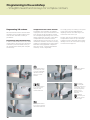
– Graphic support in any situation
Programming graphics
The two-dimensional programming
graphics give you additional security: while
you are programming, the TNC 320 draws
every entered traverse command on the
screen.
Program verification graphics
To play it safe before running a program,
the TNC 320 can graphically simulate the
machining of the workpiece. It can display
the simulation in the following ways:
• In a plan view with different shades of
depth
• In three planes (as in the workpiece
drawing)
• In a solid model, 3-D view
Details can be displayed in magnification.
In addition, the TNC 320 indicates the
calculated machining time in hours, minutes
and seconds.
Program-run graphics
On the TNC 320, you can run the
programming graphics or verification
graphics even while the workpiece is being
machined. Also, it shows a real-time
graphic of the machining progress during
program run. Coolant spray and protective
enclosures usually obstruct any direct view
of the actual workpiece. You can get around
this with a simple keystroke to see the
simulated progress of workpiece
machining.
Help graphics
During cycle programming in the plainlanguage dialog, the TNC shows a separate
illustration for each parameter. This makes
it easier to understand the function and
accelerates programming.
15
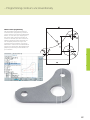
Programming in the workshop
– Straightforward function keys for complex contours
Programming 2-D contours
Two-dimensional contours are the bread
and butter of the modern machine shop.
Here the TNC 320 offers a variety of
possibilities.
Programming with path function keys
If contours are dimensioned for NC, which
means that the end points are specified in
Cartesian or polar coordinates, then you
can program them directly with the path
function keys.
Straight and circular contour elements
To program a line segment, for example,
simply press the key for linear traverse. The
TNC 320 asks for all information required
for a complete programming block, such as
target coordinates, feed rate, cutter radius
compensation and machine functions.
Appropriate path function keys for circular
movement, chamfers, and corner rounding
simplify your programming. To avoid surface
blemishes during approach or departure
from the contour, it must be approached
smoothly—that is, tangentially.
Circular path defined
by its end point, with
a smooth (tangential)
departure from the
previous contour
element
Circular path defined
by its center point,
end point, and
rotational direction
You simply specify the starting or end point
of the contour and the approaching or
departing radius of the cutter edge—the
control does the rest for you.
The TNC 320 can look ahead over a radiuscompensated contour for up to 99 blocks
to watch for back cutting and avoid contour
damage such as can occur when roughing
a contour with a large tool.
Straight line defined
by its end point
Rounding:
circular path
defined by radius and
corner point, with a
smooth (tangential)
transition to its
adjoining contour
elements
Chamfer:
defined by the
corner point and the
chamfer length
Circular path defined
by its radius, end point
and rotational direction
16
– Programming contours unconventionally
FK free contour programming
Not all workpieces are dimensioned for
conventional NC programming. Thanks to
FK, the control’s free contour programming
feature, in such cases you simply type in
the known data—without first having to
convert or calculate your data! It does not
matter if individual contour elements are
not completely defined as long as the
complete contour has been. If the given
data result in more than one mathematical
solution, the helpful TNC 320 programming
graphics present the possible variants for
your selection.
17
Programming in the workshop
– Field-proven cycles for recurring operations
Comprehensive fixed cycles for
milling, drilling and boring
Frequently recurring operations that
comprise several working steps are stored
in the TNC 320 as cycles. You program
them under conversational guidance and
are supported by graphics that clearly
illustrate the required input parameters.
Standard cycles
Besides the fixed cycles for drilling, tapping
(with or without floating tap holder), thread
milling, reaming and boring, there are
cycles for hole patterns and milling cycles
for clearing plane surfaces, and for
roughing and finishing pockets, slots and
studs.
18
Cycles for complex contours
Clearing pockets with combined contours
is aided greatly by Subcontour List cycles
(SL). This term is used to identify machining
cycles for pilot drilling, roughing and
finishing when the contour or subcontours
are specified in subroutines. In this way,
one contour description can be used for
more than one operation using different
tools.
Up to twelve subcontours can be
superimposed for machining. The control
automatically calculates the resulting
contour and the tool paths for roughing or
clearing the surfaces. Subcontours can be
pockets or islands. Different components
are combined to form a single pocket in
which the tool avoids the islands.
The TNC 320 maintains a finishing
allowance on the wall and floor surfaces
during roughing. When roughing with
different tools, the control identifies
material remaining in inside corners so that
it can be cleared later with smaller tools.
A separate cycle is used for milling to the
finished dimension.
OEM cycles
As original equipment manufacturers
(OEMs), machine tool builders can
contribute their special manufacturing
know-how by designing additional fixed
cycles and saving them in the TNC 320.
However, the end user can write his own
cycles as well. HEIDENHAIN makes this
possible with its PC program CycleDesign.
CycleDesign enables you to organize the
input parameters and soft-key structure of
the TNC 320 to suit your own needs.
Stay simple and flexible when
programming machining patterns
Machining positions are often arranged in
patterns on the workpiece. With the
TNC 320, you can program very diverse
machining patterns simply and extremely
flexibly—of course with graphic support.
You can define as many point patterns as
desired with various numbers of points.
3-D machining with parametric
programming
With parameter functions you can program
simple 3-D geometric figures that can easily
be described mathematically. Here you
can use the basic arithmetical operations,
trigonometric functions, roots, powers,
logarithmic functions, parentheses, and
logical comparisons with conditional jump
instructions. Parametric programming also
offers you a simple method of realizing
3-D operations. Of course, parametric
programming is also suited for 2-D contours
that cannot be described with line segments
or circular arcs, but rather through
mathematical functions.
19
Programming in the workshop
– Reusing programmed contour elements
Coordinate transformation
If you should need a contour that has
already been programmed at another
position or in a different size, the TNC 320
offers you a simple solution: coordinate
transformation.
With coordinate transformation you can,
for example, rotate or mirror the
coordinate system, or shift the datum.
With a scaling factor you can enlarge or
reduce contours to respect shrinkage or
oversizes.
Program section repeats, subprograms,
program calls
Many machining operations repeat
themselves either on the same workpiece
or on different workpieces. Once you have
programmed a detail there is no reason
to have to program it again. With its
subprogramming feature, the TNC can save
you a great deal of programming time.
In program section repetition, you label a
section of the program and during program
run the TNC repeats the section successively
as many times as required.
You can mark a program section as a
subprogram and then call it at any point in
the program and as often as you want.
With the program call function you can
even use a completely separate program at
any place in your current program. This gives
you convenient access to pre-programmed,
frequently needed working steps or
contours.
Of course you can also combine these
programming techniques.
20
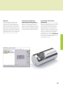
– Fast availability of all information
Do you have questions on a programming
step, but your User’s Manual is not at hand?
No problem: The TNC 320 numerical control
and TNC 320 programming station now
feature TNCguide, a convenient help system
that can show the user documentation in a
separate window.
You can activate TNCguide by simply
pressing the help key on the TNC keyboard
or by clicking any soft key with a cursor in
the shape of a question mark. You switch
the cursor by simply clicking the help
symbol
that appears on all TNC screens.
TNCguide usually displays the information
in the immediate context of the element in
question (context-sensitive help). This
means that you immediately receive the
relevant information. This function is
particularly helpful with the soft keys. The
method and effect of operation are
explained in detail.
TNCguide integrated in the control, e.g. on the TNC 320 ...
You can download the documentation in
the desired language free of charge from
the HEIDENHAIN homepage into the
corresponding language directory on the
TNC hard disk.
The following manuals are available in the
help system:
• User’s Manual for Conversational
Programming
• User’s Manual for Cycle Programming
• User’s Manual for DIN/ISO Programming
• User’s Manual for the TNC 320
Programming Station (only included in
the programming station)
… or at a programming station
21
Open for communication
– Fast data transfer with the TNC
The networked TNC 320
The TNC 320 can be integrated into
networks and connected with PCs,
programming stations and other data
storage devices. Even in its standard
version, the TNC 320 features a latestgeneration Fast Ethernet interface in
addition to its RS-232-C/V.24 data interface.
The TNC 320 communicates with NFS
servers and Windows networks in TCP/IP
protocol without needing additional
software. The fast data transfer at rates of
up to 100 Mbps guarantees very short
transfer times.
The transmitted programs are saved in the
internal memory of the TNC 320 and are
run from it at high speed.
For well-organized program management
on your control, simply place the individual
files in directories (folders). You can
structure the respective directories through
individual subdirectories.
22
Company Network
Programming
system
TNC 320
Ethernet
interface
TNC 620
Ethernet
interface
iTNC 530
Ethernet
interface
Programs for data transfer
With the aid of the free PC software
TNCremo from HEIDENHAIN and an
Ethernet or other data interface you can
• transfer remotely stored part programs
and tool or pallet tables in both directions
and
• make backups.
With the powerful TNCremoPlus PC
software you can also transfer the screen
contents of the control to your PC using
the live-screen function.
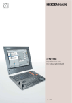
– The TNC 320 programming station
Why a programming station?
It’s well known that it is easy to create part
programs on a TNC 320 at the machine,
even while another part is being machined.
Nevertheless, it can often happen that
short reloading times and other machining
tasks hinder any prolonged or concentrated
programming work. With the TNC 320
programming station you have the capability
to program just as you do at the machine,
but away from the noise and distractions of
the shop floor.
Your workstation
The programming station software runs on
a PC. The PC screen shows you the TNC
user interface as on the control, and offers
the familiar graphic support. Depending on
the version of the programming station,
there are several types of possibilities for
using it.
The free demo version contains all
functions of the TNC 320, and permits
short programs to be saved. It is
programmed over the PC keyboard.
On the version with the TE 520B TNC
operating panel you then create your
programs as always, on a keyboard with
the same function keys as the control on
the machine. It also has a PC keyboard for
G-code programming, file names and
comments.
But you can also work without the TNC
operating panel: a virtual keyboard
simulating the TE appears on the PC
screen. It provides the TNC 320’s most
important dialog initiation keys.
Creating programs
Programming, testing and optimizing
HEIDENHAIN conversational or DIN/ISO
programs for the TNC 320 with the
programming station substantially reduces
machine idle times. You need not adjust
your way of thinking—every keystroke fits.
On the programming station you program
on the same keyboard as at the machine.
Testing of programs created offline
Of course you can also test programs that
were written on a CAD/CAM system. The
various views of the program verification
graphics help you to easily spot contour
damage and hidden details.
Training with the TNC 320 programming
station
Because the TNC 320 programming station
is based on the same software as the
TNC 320, it is ideally suited for apprentice
and advanced training. The program is
entered on the original keyboard unit. Even
the test run functions exactly as it does on
the machine. This gives the trainee the
experience needed to enable him or her to
safely operate the machine later.
Because the TNC 320 can be programmed
in plain language and in DIN/ISO, the
TNC 320 programming station can also be
used in schools for TNC programming
training.
More information about the programming
station and a free demo version is available
on the Internet at www.heidenhain.de.
Or simply ask for the TNC 320
Programming Station CD or brochure.
Programming station with TNC operating panel
23
Workpiece measurement
– Setup, presetting and measuring with touch trigger probes
Workpiece touch probes from HEIDENHAIN
help you to reduce costs in the workshop
and in series production: Together with the
TNC 320, touch probes can automatically
perform setup, measuring and inspection
functions.
The stylus of a TS touch trigger probe is
deflected upon contact with a workpiece
surface. At that moment the TS generates
a trigger signal that, depending on the
model, is transmitted either by cable or
over an infrared beam to the control.
The touch probe* is inserted directly into
the machine tool spindle. It can be
equipped with various shanks depending
on the machine. The ruby ball tips are
available in several diameters, and the styli
in different lengths.
Touch probes with cable connection for
signal transmission for machines with
manual tool change:
TS 220 – Compact dimensions, with cable
connection
Touch probes with infrared signal
transmission for machines with automatic
tool change:
TS 440 – Compact dimensions
TS 444 – Compact dimensions, batteryfree power supply through integrated air
turbine generator over central compressed
air supply
TS 640 – Standard touch probe with widerange infrared transmission
TS 740 – High probing accuracy and
repeatability, low probing force
* The touch probes must be interfaced to the TNC 320
by the machine tool builder.
SE 640
TS 220
TS 640
TS 440
More information about workpiece touch
probes is available on the Internet at
www.heidenhain.de or in the Touch
Probes brochure or CD.
24
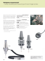
Tool measurement
– Measuring length, radius and wear directly in the machine
The tool is of course a decisive factor in
ensuring a consistently high level of
production quality. This means that an
exact measurement of the tool dimensions
and periodic inspection of the tool for wear
and breakage, as well as the shape of each
tooth, are necessary. HEIDENHAIN offers
the TT trigger tool touch probes as well as
the non-contacting TL Nano and TL Micro
laser systems for tool measurement.
The systems are installed directly in the
machine’s workspace, where they permit
tool measurement either before machining
or during interruptions.
The TT tool touch probes measure the
tool length and radius. When probing the
tool, either while rotating or at standstill
(such as for measuring individual teeth),
the contact plate is deflected and a trigger
signal is transmitted to the TNC 320.
The TT 140 uses signal transmission by
cable whereas the TT 449 operates with
signal transmission over infrared beam and
does not require a cable. It is therefore
particularly suitable for use on rotary and
tilting tables.
The TL Nano and TL Micro laser systems
are available for various maximum tool
diameters. Using a laser beam, they probe
the tool without contact, and can detect
form deviations of individual teeth along
with the tool length and radius.
TT 449
TL Micro
More information about tool touch
probes is available on the Internet at
www.heidenhain.de or in the Touch
Probes brochure or CD.
25
Positioning with the electronic handwheel
– Delicate axis traverse
To set up the workpiece you can use the
direction keys to move the machine axes
manually. A simpler and more sensitive
way, however, is to use the electronic
handwheels from HEIDENHAIN.
You can move the axis slide through the
feed motors in direct relation to the
rotation of the handwheel. For delicate
operations you can set the transmission
ratio to certain preset distances per
handwheel revolution.
Panel-mounted handwheels
The HR 130 and HR 150 panel-mounted
handwheels from HEIDENHAIN can be
integrated in the machine operating panel
or mounted at another location on the
machine. An adapter permits connection of
up to three HR 150 electronic handwheels.
Portable handwheels
The portable HR 410, HR 520 and HR 550
handwheels are particularly helpful for when
you have to work close to the machine’s
working space. The axis keys and certain
functional keys are integrated in the housing.
This way you can switch axes and set up the
machine at any time—regardless of where
you happen to be standing. The HR 520 and
HR 550 handwheels feature an integrated
display for user-friendly remote operation of
the control. As a wireless handwheel, the
HR 550 is ideal for use on large machine
tools. If you no longer need the handwheel,
just attach it to the machine somewhere by
its built-in magnets.
The HR 520 and HR 550 provide the
following functions:
• Traverse distance per revolution can be set
• Display for operating mode, actual
position value, programmed feed rate
and spindle speed, error messages
• Override potentiometer for feed rate and
spindle speed
• Selection of axes via keys or soft keys
• Keys for continuous traverse of the axes
• Emergency stop button
• Actual position capture
• NC start/stop
• Spindle on/off
• Soft keys for machine functions defined
by the machine tool builder
HR 550
26
Overview
– Specifications
Specifications
Components
• Main computer with TNC keyboard and integrated 15.1-inch TFT color flat-panel display with soft keys
Operating system
• HEROS 4 real-time operating system for machine control
Memory
• 300 MB (on compact flash memory card CFR)
Input resolution and
display step
• Linear axes: to 0.1 µm
• Angular axes: to 0.0001°
Input range
• Maximum: 99 999.999 mm or 99 999.999°
Interpolation
•
•
•
•
Block processing time
• 6 ms (3-D straight line without radius compensation)
Axis feedback control
• Position loop resolution: Signal period of the position encoder/1024
• Cycle time of position controller: 3 ms
Range of traverse
• Maximum 100 m
Spindle speed
• Maximum 100 000 rpm (analog speed command signal)
Error compensation
• Linear and nonlinear axis error, backlash, reversal spikes during circular movements, thermal expansion
• Stick-slip friction
Data interfaces
• RS-232-C/V.24 max. 115 Kbps
• Extended data interface with LSV2 protocol for remote operation of the TNC 320 over the data interface
with the HEIDENHAIN software TNCremo or TNCremoPlus
• 100BaseT Fast Ethernet interface
• 3 x USB 2.0
Diagnostics
• Fast and simple troubleshooting through integrated diagnostic aids
Ambient temperature
• Operation: 5 °C to +45 °C
• Storage: –35 °C to +65 °C
Linear in 4 axes
Circular in 2 axes
Circular in 3 axes with tilted working plane
Helical: superimposition of circular and straight paths
27
Overview
– User functions
Brief description
Option
Standard
User functions
•
Basic version: 3 axes plus closed-loop spindle
1st additional axis for 4 axes plus Open-Loop or Closed-Loop spindle
2nd additional axis for 5 axes plus Open-Loop spindle
Program entry
•
•
In HEIDENHAIN plain language
As per ISO over soft keys or USB keyboard
Position entry
•
•
•
Nominal positions for lines and arcs in Cartesian coordinates or polar coordinates
Incremental or absolute dimensions
Display and input in mm or inches
Tool compensation
•
•
Tool radius in the working plane and tool length
Radius-compensated contour look-ahead for up to 99 blocks (M120)
Tool tables
•
Multiple tool tables with any number of tools
Constant contour speed
•
•
Relative to the path of the tool center
Relative to the tool’s cutting edge
Parallel operation
•
Creating a program with graphical support while another program is being run
Rotary table machining
8
8
Programming of cylindrical contours as if in two axes
Feed rate in mm/min
Contour elements
•
•
•
•
•
•
•
Straight line
Chamfer
Circular path
Circle center point
Circle radius
Tangentially connecting circular arc
Corner rounding
Approaching and
departing the contour
•
•
Via straight line: tangential or perpendicular
Via circular arc
FK free contour
programming
•
FK free contour programming in HEIDENHAIN conversational format with graphic support for
workpiece drawings not dimensioned for NC
Program jumps
•
•
•
Subroutines
Program-section repeat
Calling any program as a subprogram
Fixed cycles
•
•
•
•
•
•
•
•
•
•
Cycles for drilling, pecking, reaming, boring, counterboring, conventional and rigid tapping
Cycles for milling internal and external threads
Rectangular and circular pockets
Cycles for clearing level and inclined surfaces
Multioperation machining of straight and circular slots
Multioperation machining of rectangular and circular pockets
Cartesian and polar point patterns
Contour train, contour-parallel contour pocket
OEM cycles (special cycles developed by the machine tool builder) can be integrated
Engraving cycle: Engrave text or numbers on a straight line and circular arc
Coordinate transformation •
8
28
Datum shift, rotation, mirror image, scaling factor (axis-specific)
Tilting the working plane, PLANE function
Standard
Option
User functions
Q parameters
Programming with variables
•
Mathematical functions =, +, –, *, /, sin , cos , tan , arc sin, arc cos, arc tan, an, en, In, log,
√a, √a2 + b2
•
•
•
•
Logical operations (=, = /, <, >)
Calculating with parentheses
Absolute value of a number, constant , negation, truncation of digits before or after the decimal point
Functions for calculation of circles
Programming aids
•
•
•
•
•
•
Calculator
Complete list of all current error messages
Context-sensitive help function for error messages
TNCguide: The integrated help system. User information available directly on the TNC 320
Graphic support for programming cycles
Comment and structure blocks in the NC program
Actual position capture
•
Actual positions can be transferred directly into the NC program
Program verification
graphics
Display modes
•
•
•
Graphic simulation before a program run, even while another program is running
Plan view / projection in 3 planes / 3-D view, also in tilted working plane
Magnification of details
Programming graphics
•
In the Programming and Editing mode, the contour of the NC blocks is drawn on screen while the
blocks are being entered (2-D pencil-trace graphics), even while another program is running
Program-run graphics
Display modes
•
•
Graphic simulation during real-time machining
Plan view / projection in 3 planes / 3-D view
Machining time
•
•
Calculation of machining time in the Test Run operating mode
Display of the current machining time in the Program Run operating modes
Returning to the contour
•
•
Mid-program startup in any block in the program, returning the tool to the calculated nominal
position to continue machining
Program interruption, contour departure and return
Datum management
•
For saving any reference points
Datum tables
•
Several datum tables for storing workpiece-related datums
Touch probe cycles
•
•
•
•
Touch probe calibration
Compensating workpiece misalignment
Datum setting, manual or automatic
Automatic tool and workpiece measurement
Parallel secondary axes
•
•
Compensating movement in the secondary axis U, V, W through the principal axis X, Y, Z
Including movements of parallel axes in the position display of the associated principal axis
(sum display)
Defining the principal and secondary axes in the NC program makes it possible to run programs
on different machine configurations
•
Conversational languages
•
English, German, Chinese (traditional, simplified), Czech, Danish, Dutch, Finnish, French,
Hungarian, Italian, Polish, Portuguese, Russian (Cyrillic), Spanish, Swedish
41 For more conversational languages, see Options
29
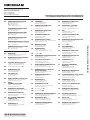
– Options
Option
Option
number
As of NC
software
340551-
ID
Comment
Additional axis
–
01
–
• 1st additional axis for 4 axes plus Open-Loop or Closed-Loop spindle
• 2nd additional axis for 5 axes plus Open-Loop spindle
Software option 1
8
01
536164-01
Rotary table machining
• Programming of cylindrical contours as if in two axes
• Feed rate in mm/min
Additional Language
41
03
Interpolation
• Circular in 3 axes with tilted working plane
Coordinate transformation
• Tilting the working plane
04
• PLANE function
04
530184-01
-02
-03
-04
-06
-07
-08
-09
-10
30
Additional conversational languages
• Slovenian
• Slovak
• Latvian
• Norwegian
• Korean
• Estonian
• Turkish
• Romanian
• Lithuanian
– Accessories
Accessories
Electronic handwheels
•
•
•
•
•
One HR 410 portable handwheel
One HR 520 portable handwheel with display, or
One HR 550 portable wireless handwheel with display, or
One HR 130 panel-mounted handwheel or
Up to three HR 150 panel-mounted handwheels via HRA 110 handwheel adapter
Workpiece measurement
•
•
•
•
•
TS 220: Touch trigger probe with cable connection or
TS 440: Touch trigger probe with infrared transmission or
TS 444: Touch trigger probe with infrared transmission or
TS 640: Touch trigger probe with infrared transmission or
TS 740: Touch trigger probe with infrared transmission
Tool measurement
•
•
•
•
TT 140: 3-D touch trigger probe or
TS 449: 3-D touch trigger probe with infrared transmission
TL Nano: Laser system for contact-free workpiece measurement or
TL Micro: Laser system for contact-free workpiece measurement
Software for PCs
•
•
•
•
TeleService: Software for remote diagnostics, monitoring, and operation
CycleDesign: Software for creating your own cycle structure
TNCremo: Software for data transfer—free of charge
TNCremoPlus: Software for data transfer with live-screen function
Programming station
Control software for PCs for programming, archiving, and training
• Single-station license with original control keyboard
• Single-station license with virtual keyboard
• Network license with virtual keyboard
• Demo version (operated via virtual keyboard or PC keyboard—free of charge)
31
DR. JOHANNES HEIDENHAIN GmbH
Dr.-Johannes-Heidenhain-Straße 5
83301 Traunreut, Germany
{ +49 8669 31-0
| +49 8669 5061
E-mail: [email protected]
DE
HEIDENHAIN Vertrieb Deutschland
83301 Traunreut, Deutschland
08669 31-3132
08669 32-3132
E-Mail: [email protected]
DK
TP TEKNIK A/S
2670 Greve, Denmark
www.tp-gruppen.dk
NO
HEIDENHAIN Scandinavia AB
7300 Orkanger, Norway
www.heidenhain.no
ES
PH
HEIDENHAIN Technisches Büro Nord
12681 Berlin, Deutschland
030 54705-240
FARRESA ELECTRONICA S.A.
08028 Barcelona, Spain
www.farresa.es
Machinebanks` Corporation
Quezon City, Philippines 1113
E-mail: [email protected]
FI
PL
HEIDENHAIN Technisches Büro Mitte
08468 Heinsdorfergrund, Deutschland
03765 69544
HEIDENHAIN Scandinavia AB
02770 Espoo, Finland
www.heidenhain.fi
APS
02-384 Warszawa, Poland
www.heidenhain.pl
FR
PT
HEIDENHAIN Technisches Büro West
44379 Dortmund, Deutschland
0231 618083-0
HEIDENHAIN FRANCE sarl
92310 Sèvres, France
www.heidenhain.fr
FARRESA ELECTRÓNICA, LDA.
4470 - 177 Maia, Portugal
www.farresa.pt
GB
RO
HEIDENHAIN Technisches Büro Südwest
70771 Leinfelden-Echterdingen, Deutschland
0711 993395-0
HEIDENHAIN (G.B.) Limited
Burgess Hill RH15 9RD, United Kingdom
www.heidenhain.co.uk
HEIDENHAIN Reprezentanţă Romania
Braşov, 500407, Romania
www.heidenhain.ro
GR
MB Milionis Vassilis
17341 Athens, Greece
www.heidenhain.gr
RS
Serbia BG
RU
OOO HEIDENHAIN
125315 Moscow, Russia
www.heidenhain.ru
SE
HEIDENHAIN Scandinavia AB
12739 Skärholmen, Sweden
www.heidenhain.se
HEIDENHAIN Technisches Büro Südost
83301 Traunreut, Deutschland
08669 31-1345
AR
AT
AU
NAKASE SRL.
B1653AOX Villa Ballester, Argentina
www.heidenhain.com.ar
HEIDENHAIN LTD
Kowloon, Hong Kong
E-mail: [email protected]
HR
Croatia SL
HU
SG
HEIDENHAIN Techn. Büro Österreich
83301 Traunreut, Germany
www.heidenhain.de
HEIDENHAIN Kereskedelmi Képviselet
1239 Budapest, Hungary
www.heidenhain.hu
HEIDENHAIN PACIFIC PTE LTD.
Singapore 408593
www.heidenhain.com.sg
ID
SK
FCR Motion Technology Pty. Ltd
Laverton North 3026, Australia
E-mail: [email protected]
PT Servitama Era Toolsindo
Jakarta 13930, Indonesia
E-mail: [email protected]
KOPRETINA TN s.r.o.
91101 Trencin, Slovakia
www.kopretina.sk
IL
NEUMO VARGUS MARKETING LTD.
Tel Aviv 61570, Israel
E-mail: [email protected]
SL
Posredništvo HEIDENHAIN
NAVO d.o.o.
2000 Maribor, Slovenia
www.heidenhain-hubl.si
IN
HEIDENHAIN Optics & Electronics
India Private Limited
Chetpet, Chennai 600 031, India
www.heidenhain.in
TH
HEIDENHAIN (THAILAND) LTD
Bangkok 10250, Thailand
www.heidenhain.co.th
BA
Bosnia and Herzegovina SL
BE
HEIDENHAIN NV/SA
1760 Roosdaal, Belgium
www.heidenhain.be
BG
HK
ESD Bulgaria Ltd.
Sofia 1172, Bulgaria
www.esd.bg
IT
HEIDENHAIN ITALIANA S.r.l.
20128 Milano, Italy
www.heidenhain.it
TR
DIADUR Indústria e Comércio Ltda.
04763-070 – São Paulo – SP, Brazil
www.heidenhain.com.br
JP
HEIDENHAIN K.K.
Tokyo 102-0083, Japan
www.heidenhain.co.jp
TW
HEIDENHAIN Co., Ltd.
Taichung 40768, Taiwan R.O.C.
www.heidenhain.com.tw
Belarus
GERTNER Service GmbH
50354 Huerth, Germany
www.gertnergroup.com
KR
HEIDENHAIN Korea LTD.
Gasan-Dong, Seoul, Korea 153-782
www.heidenhain.co.kr
UA
Gertner Service GmbH Büro Kiev
01133 Kiev, Ukraine
www.gertnergroup.com
HEIDENHAIN CORPORATION
Mississauga, OntarioL5T2N2, Canada
www.heidenhain.com
ME
Montenegro SL
US
MK
Macedonia BG
HEIDENHAIN CORPORATION
Schaumburg, IL 60173-5337, USA
www.heidenhain.com
CH
HEIDENHAIN (SCHWEIZ) AG
8603 Schwerzenbach, Switzerland
www.heidenhain.ch
MX
HEIDENHAIN CORPORATION MEXICO
20235 Aguascalientes, Ags., Mexico
E-mail: [email protected]
VE
Maquinaria Diekmann S.A.
Caracas, 1040-A, Venezuela
E-mail: [email protected]
CN
DR. JOHANNES HEIDENHAIN
(CHINA) Co., Ltd.
Beijing 101312, China
www.heidenhain.com.cn
MY
ISOSERVE Sdn. Bhd
56100 Kuala Lumpur, Malaysia
E-mail: [email protected]
VN
AMS Co. Ltd
HCM City, Vietnam
E-mail: [email protected]
NL
HEIDENHAIN s.r.o.
102 00 Praha 10, Czech Republic
www.heidenhain.cz
HEIDENHAIN NEDERLAND B.V.
6716 BM Ede, Netherlands
www.heidenhain.nl
ZA
CZ
MAFEMA SALES SERVICES C.C.
Midrand 1685, South Africa
www.heidenhain.co.za
BR
BY
CA
551025-27 · 10 · 9/2012 · H · Printed in Germany
·
T&M Mühendislik San. ve Tic. LTD. ŞTI.
34728 Ümraniye-Istanbul, Turkey
www.heidenhain.com.tr
Zum Abheften hier falzen! / Fold here for filing!
Vollständige und weitere Adressen siehe www.heidenhain.de
For complete and further addresses see www.heidenhain.de
www.heidenhain.de