1
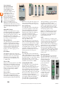
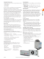
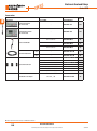
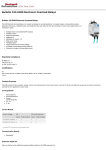
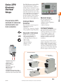
Choose Series CEP9
overloads for advanced
communication and
motor protection
The CEP9 Electronic Overload Relay
is the next generation electronic
overload from Sprecher + Schuh. Its
modular design, communication options, diagnostic information, simplifi
ed wiring and integration into Logix
make this the ideal overload for motor
control applications in an automation
system. The CEP9 Overload Relay
provides fl exibility, reduces engineering time and maximizes uptime for
important motor starter applications.
Intelligent Motor
Protection
Easy automation system integration
• Network Connectivity
• Native I/O
• DeviceLogix™ Technology Enabled
• Pre-programmed Operating Modes
Diagnostic Information
Monitor motor performance
• Voltage, Current and Energy
• Trip / Warning Histories
• % Thermal Capacity Utilization
• Time to Trip
• Time to Reset
• Operational Hours
• Number of Starts
• Snapshot Log
B
Modular Design
For exact application needs
• Wide Current Range
• Multiple Sensing Capabilities
• Expansion I/O
• Operator Interface
On Board Features
The newly designed CEP9 Overload
Relay has incorporated the newest
technologies directly into the device
to help simplify installation and
configuration. Simplified wiring
between the CEP9 overload relay
and CA7 contactor ensure easy
installation.
On-device settings include network
address configuration, restore factory
default settings, and enable security
settings. CEP9 overloads also include
removable terminal blocks, I/O and
Operator Station Dual Port EtherNet/
IP, and it supports device level ring.
Communication Module
= Complete CEP9
Overload Relay
• Intelligent motor protection
(EtherNet/IP enabled)
•Scalable solution
•Diagnostic Information
•Integrated I/O
•Adjustable trip class 5...30
•Wide current range
•Test/Reset button
•Programmable trip and warning settings
•True RMS current/voltage sensing (50/60 Hz)
•Protection for single- and three-phase motors
+ Control Module
+ Sensing Module
B43
SSNA2014
visit www.sprecherschuh.com/ecatalog for the most up to date information
CEP9 Overloads
Series CEP9
Electronic
Overload
Relays
Thermal Overload
CEP9 Overloads
B
Thermal Utilization
The CEP9 Electronic
Overload Relay provides
overload protection
through true RMS current
measurement of the
individual phase currents
of the connected motor.
Based on this information,
a thermal model that
simulates the actual heating
of the motor is calculated.
Percent of thermal capacity
utilization (%TCU) reports this
calculated value and can be read via a
communications network. An overload
trip occurs when the value reaches
100%.
Diagnostic Station
Expansion Modules
the reset level. As this value decays, the
time to reset, which is accessible via a
communications network, is reported.
Thermal Warning
The CEP9 Electronic Overload Relay
provides the capability to alert in the
event of an impending overload trip.
A thermal warning bit is set in the
Warning Status when the calculated
percentage of thermal capacity
utilization exceeds the programmed
thermal warning level, which has a
setting range of 0...100% TCU.
Adjustable Settings
Thermal overload protection setup is
accomplished simply by programming
the motor’s full load current (FLC)
rating and the desired trip class (5...30).
Programming of the actual values
through software programming ensures
the accuracy of the protection.
Two-Speed Protection
The CEP9 Electronic Overload Relay
offers a second FLA setting for 2-speed
motor protection. What used to require
two separate overload relays - one for
each set of motor windings - can now be
accomplished with one device. Improved
protection is delivered as thermal
utilization is maintained in one device
during operation in both speeds.
Thermal Memory
The CEP9 Electronic Overload Relay
includes a thermal memory circuit
designed to approximate the thermal
decay for a trip class 20 setting. This
means that the thermal model of the
connected motor is maintained at
all times, even if the supply power is
removed.
Reset Modes
This flexibility allows the end-user in
the ability to select between manual and
automatic reset for an overload trip,
allowing for broad application. The
point of reset is user adjustable from
1...100% TCU.
Time to Trip
During an overload condition, the CEP9
Electronic Overload Relay provides an
estimated time to trip that is accessible
via a communications network. This
allows corrective action to be taken
so that production may continue
uninterrupted.
Time to Reset
Following an overload trip, the CEP9
Electronic Overload Relay will not
reset until the calculated percentage of
thermal capacity utilization falls below
Phase Loss
The CEP9 Electronic Overload Relay
offers configurable phase loss protection,
allowing the installer to enable or disable
the function plus set a time delay setting,
adjustable from 0.1...25.0 seconds.
The trip level is factory-set at a current
imbalance measurement of 100%.
Ground (Earth) Fault
The CEP9 Electronic Overload Relay
incorporates zero sequence (core
balance) sensing into its design for low
level (arcing) ground fault detection.
Trip and warning settings are adjustable
from 20 mA...5.0 A. For devices rated
greater than 200 A and for ground fault
detection less than 1.0 A, the external
core balance current transformer
accessory is required. Class I protection
is provided as defined by UL1053.
The CEP9 Electronic Overload Relay
provides a max. trip-inhibit setting,
offering flexibility to prevent tripping
when the ground fault current
magnitude exceeds 6.5 A. This can be
useful to guard against the opening of
the controller when the fault current
could potentially exceed the controller’s
interrupting capacity rating.
Note: The CEP9 Electronic Overload
Relay is not a Ground Fault Circuit
Interrupter for personnel protection
as defined in article 100 of the U.S.
National Electric Code.
Stall
“Stall” is defined as a condition where
the motor is not able to reach full-speed
operation in the appropriate amount
of time required by the application.
This can result in motor overheating as
current draw is in excess of the motor’s
full load current rating. The CEP9
Electronic Overload Relay provides
user-adjustable stall protection. The trip
setting has a range of 100...600% FLA,
and the enable time is adjustable up to
250 seconds.
Jam (Overcurrent)
The CEP9 Electronic Overload Relay
can respond quickly to take a motor
off-line in the event of a mechanical jam,
thereby reducing the
potential for damage
to the motor and the
power transmission
components.
Trip adjustments
include a trip setting
adjustable from
50...600% FLA and
a trip delay time with
a range of 0.1...25.0
seconds. A separate
warning setting is
adjustable from
50...600% FLA.
B44
visit www.sprecherschuh.com/ecatalog for the most up to date information
SSNA2014
For these instances, rapid fault detection can help minimize
damage and aid in reducing production downtime.
Additionally, monitoring for an underload event can provide
enhanced protection for motors that are coded by the medium
handled (e.g., submersible pumps that pump water). Such
motors can become overheated despite being underloaded.
This can result from an absence or an insufficient amount of
the medium (due to clogged filters, closed valves, etc.).
The CEP9 Electronic Overload Relay offers underload trip
and warning settings adjustable from 10...100% FLA. The
trip function also includes a trip delay time with a range of
0.1...25.0 seconds.
Current Imbalance (Asymmetry)
The CEP9 Electronic Overload Relay offers current imbalance
trip and warning settings adjustable from 10...100%. The
trip function also includes a trip delay time with a range of
0.1...25.0 seconds.
Remote Trip
The remote trip function allows an external device (e.g., a
vibration sensor) to induce the CEP9 Electronic Overload
Relay to trip. External device relay contacts are wired to
the CEP9 Electronic Overload Relay discrete inputs. These
discrete inputs are configurable with an option for assigning
the remote trip function.
Current Monitoring Functions
The CEP9 Electronic Overload Relay allows the user to
monitor the following operational data over a communications
network:
• Individual phase currents — in amperes
• Individual phase currents — as a percentage of motor FLC
• Average current — in amperes
• Average current — as a percentage of motor FLC
• Percentage of thermal capacity utilized
• Current imbalance percentage
• Ground fault current
Diagnostic Functions
The CEP9 Electronic Overload Relay allows the user to
monitor the following diagnostic information over the
DeviceNet network:
• Device status
• Trip status
• Warning status
• Time to an overload trip
• Time to reset after an
overload
Status Indicators
The CEP9 Electronic Overload Relay provides the following
LED indicators:
• Power — This green/red LED indicates the status of the
overload relay.
• TRIP/WARN — This LED flashes a yellow code under a
warning condition and a red code when tripped.
Inputs/Outputs
Inputs allow the connection of such devices as contactor and
disconnect auxiliary contacts, pilot devices, limit switches,
and float switches. Input status can be monitored via the
network and mapped to a controller’s input image table.
Inputs are rated 24V DC, 120V AC, or 240V AC and are
current sinking. Power for the inputs is sourced separately with
convenient customer sources at terminal A1. Relay contact
outputs can be controlled via the network or DeviceLogix
function blocks for performing such tasks as contactor
operation.
Test/Reset Button
The Test/Reset button, located on the front of the CEP9
Electronic Overload Relay, allows the user to perform the
following:
• Test — The trip relay contact will open if the CEP9
Electronic Overload Relay is in an untripped condition and
the Test/Reset button is pressed for 2 seconds or longer.
• Reset — The trip relay contact will close if the CEP9
Electronic Overload Relay is in a tripped condition, supply
voltage is present, and the Test/Reset button is pressed.
Single/Three-Phase Operation
The CEP9 Electronic Overload Relay can be applied to threephase as well as single-phase applications. A programming
parameter is provided for selection between single- and threephase operation. Straight-through wiring is afforded in both
cases.
EtherNet/IP Communications
The CEP9 EtherNet/IP communication module has two RJ45
ports that act as an Ethernet switch to support a star, linear,
and ring topology and supports the following:
• 2 concurrent Class 1 connections [1 exclusive owner + (1
input only or 1 listen only)]
• 6 simultaneously Class 3
connections (explicit messaging)
• Embedded web server
• SMPT server for trip and warning
events
• Embedded EDS file
• History of past five trips
• History of positive warnings
• Hours of operation
• Number of starts
• Trip snapshot trip
B45
SSNA2014
visit www.sprecherschuh.com/ecatalog for the most up to date information
B
CEP9 Overloads
Underload (Undercurrent)
A sudden drop in motor current can signal conditions such as:
• Pump cavitation
• Tool breakage
• Belt breakage
Electronic Overload Relays
Series CEP9
Current Sensing Module
Mounting Options
For Use With
CA7-9…23
CA7-30…55
IEC Contactors
CEP9 Overloads
B
Description
DIN Rail Mount (up to 60A) ➋
DIN Rail Mount (10 to 100A) ➌
DIN Rail Mount Pass-thru (to 60A) ➋
DIN Rail Mount Pass-thru
(10 to 200A) ➌
Catalog Number
0.5…30
CEP9-ESM-I-23-30
0.5…30
CEP9-ESM-I-55-30
6…60
CEP9-ESM-I-55-60
CA7-60…97
10…100
CEP9-ESM-I-97-100
CA6-115…180
20…200
CEP9-ESM-I-180-200
Line- and load-side power
conductor terminals
Line- and load-side power
conductor terminals.
DIN Rail / Panel Mount
Current
Range [A]
Pass-thru with power
conductor apertures
0.5…30
CEP9-ESM-I-T-30
6…60
CEP9-ESM-I-T-60
10…100
CEP9-ESM-I-T-100
0.5…30
CEP9-ESM-I-7T-30
6…60
CEP9-ESM-I-7T-60
10…100
CEP9-ESM-I-7T-100
0.5…30
CEP9-ESM-I-P-30
6…60
CEP9-ESM-I-P-60
10…100
CEP9-ESM-I-P-100
20…200
CEP9-ESM-I-P-200
Price
149
149
238
315
➊
144
230
315
149
238
315
115
201
287
➊
Current/Ground Fault Sensing Module
CA7-9…23
CA7-30…55
IEC Contactors
DIN Rail Mount (up to 60A) ➋
DIN Rail Mount (10 to 100A) ➌
DIN Rail Mount Pass-thru (to 60A) ➋
DIN Rail Mount Pass-thru
(10 to 200A) ➌
CEP9-ESM-IG-23-30
CEP9-ESM-IG-55-30
6…60
CEP9-ESM-IG-55-60
CA7-60…97
10…100
CEP9-ESM-IG-97-100
CA6-115…180
20…200
CEP9-ESM-IG-180-200
Line- and load-side power
conductor terminals
Line- and load-side power
conductor terminals
DIN Rail / Panel Mount
0.5…30
0.5…30
Pass-thru with power
conductor apertures
0.5…30
CEP9-ESM-IG-T-30
6…60
CEP9-ESM-IG-T-60
10…100
CEP9-ESM-IG-T-100
0.5…30
CEP9-ESM-IG-7T-30
6…60
CEP9-ESM-IG-7T-60
10…100
CEP9-ESM-IG-7T-100
0.5…30
CEP9-ESM-IG-P-30
6…60
CEP9-ESM-IG-P-60
10…100
CEP9-ESM-IG-P-100
20…200
CEP9-ESM-IG-P-200
209
209
298
373
➊
201
287
373
209
298
373
172
258
344
➊
Voltage/Current/Ground Fault Sensing Module
CA7-9…23
CA7-30…55
IEC Contactors
DIN Rail Mount (up to 60A) ➋
DIN Rail Mount (10 to 100A) ➌
0.5…30
CEP9-ESM-VIG-23-30
0.5…30
CEP9-ESM-VIG-55-30
6…60
CEP9-ESM-VIG-55-60
CA7-60…97
10…100
CEP9-ESM-VIG-97-100
CA6-115…180
20…200
CEP9-ESM-VIG-180-200
Line- and load-side power
conductor terminals
DIN Rail / Panel Mount
Line- and load-side power
conductor terminals
DIN Rail Mount Pass-thru ➋
External Current Transformer
0.5…30
CEP9-ESM-VIG-T-30
6…60
CEP9-ESM-VIG-T-60
10…100
CEP9-ESM-VIG-T-100
0.5…30
CEP9-ESM-VIG-7T-30
6…60
CEP9-ESM-VIG-7T-60
10…100
CEP9-ESM-VIG-7T-100
0.5…30
CEP9-ESM-VIG-CT-30
387
387
476
544
➊
387
476
544
373
459
544
344
➊Future expansion. Contact factory for additional information.
➋For Panel Mount option use KT7-45-AS Screw Adaptor. See page F16.
➌For Panel Mount option use CEP9-ESM-SA-100 Screw Adaptor. See page B48.
B46
Discount Schedule B1
visit www.sprecherschuh.com/ecatalog for the most up to date information
SSNA2014
Electronic Overload Relays
Series CEP9
Control Module
Rated Control
Voltage [V]
No. of
Inputs/Outputs
110…120V AC, 50/60 Hz
4 In/3 Out
Catalog Number
CEP9-EIO-43-120
220…240V AC, 50/60 Hz
4 In/3 Out
CEP9-EIO-43-240
417
24V DC
6 In/3 Out
CEP9-EIO-63-24D
417
110…120V AC, 50/60 Hz
2 In / 2 Out
CEP9-EIOGP-22-120
401
220…240V AC, 50/60 Hz
2 In / 2 Out
CEP9-EIOGP-22-240
401
24V DC
4 In / 2 Out
CEP9-EIOGP-42-24D
401
EtherNet/IP Communication
~
~
CEP9-ECM-ETR
476
DeviceNet Communication
~
~
CEP9-ECM-DNT
➊
Parameter Configuration
~
~
CEP9-ECM-PCM
➊
PROFIBUS Communication
~
~
CEP9-ECM-PRB
➊
Analog Expansion Module
~
3 In / 1 Out
CEP9-EXP-AIO-31
459
Digital Expansion 120V AC
110…120V AC, 50/60 Hz
4 In / 2 Out
CEP9-EXP-DIO-42-120
238
Digital Expansion 240V AC
220…240V AC, 50/60 Hz
4 In / 2 Out
CEP9-EXP-DIO-42-240
238
Digital Expansion 24V DC
24V DC
4 In / 2 Out
CEP9-EXP-DIO-42-24D
238
110…240V AC, 50/60 Hz
~
CEP9-EXP-PS-AC
179
24V DC
~
CEP9-EXP-PS-DC
179
I/O Module
Ground Fault & PTC I/O
Module
Price
B
417
CEP9 Overloads
Description
Communication Module
Expansion Modules
Expansion Power Supply
➊Future expansion. Contact factory for additional information.
Discount Schedule B1
SSNA2014
visit www.sprecherschuh.com/ecatalog for the most up to date information
B47
Electronic Overload Relays
Series CEP9
Accessories
CEP9 Overloads
B
Description
For Use With
Catalog Number
Price
Starter Control Station
with 3 meter cable
~
CEP9-EOS-SCS
238
Starter Diagnostic Station
with 3 meter cable
~
CEP9-EOS-SDS
357
CA7-23 contactors
CEP9-EIO-CM-23
24
CA7-55 contactors
CEP9-EIO-CM-55
24
CA7-97 contactors
CEP9-EIO-CM-97
24
Contactor Coil Module
1 Meter
~
CEP9-EXP-CBL-1M
24
3 Meter
~
CEP9-EXP-CBL-3M
48
CEP9-NCIOGP-22-CNT
CEP9-NCIO-43-CNT
CEP9-NCIOGP-42-CNT
CEP9-NCIO-63-CNT
CEP9-NCXP-DIO-CNT
CEP9-NCXP-AIO-CNT
CEP9-NCXP-PS-CNT
➊
36
➊
36
36
36
36
CEP9-ESM-SA-100
40
Expansion Module Cable
120/240V AC 2:2 Control Modules
120/240V AC 4:3 Control Modules
24V DC 4:2 Control Modules
Replacement Connectors
24V DC 6:3 Control Modules
Digital Expansion Modules
Analog Expansion Modules
Expansion Power Supply
Panel Mount Screw Adaptor
CEP9-ESM-_-100
➊Future expansion. Contact factory for additional information.
B48
Discount Schedule B1
visit www.sprecherschuh.com/ecatalog for the most up to date information
SSNA2014
Technical Information
Series CEP9 Electronic Overload Relay
Electrical Specifications
Input Ratings (Control Module and Expansion Digital Module)
Terminals
Rated Insulation Voltage (Ui)
Rated Operating Voltage (Ue)
1/L1, 3/L2, 5/L3, 2/T1, 4/T2, 6/T3
690V AC
IEC: 690V AC
UL: 600V AC
6 kV
See Catalog Number Explanation
45...65 Hz ➊
See user manual
3
Single-phase or Three-phase
Rated Impulse Voltage (Uimp)
Rated Operating Current (Ie)
Rated Frequency
Short Circuit Ratings
Number of Poles
Application
Power Supply Ratings
Rated Supply Voltage (Us)
Operating Range
Maximum Inrush Current
Maximum Power Consumption
CEP9:
CEP9 with expansion:
Maximum Power Interruption Time
Vmin:
Vmax:
120V AC
85…132V AC
240V AC
159…265V AC
6A
6W
8W
10 ms
10 ms
10 ms
10 ms
Relay 0:
Relay 1:
Relay 2:
R03/R04
R13/R14
R23/R24
Form A
SPST - NO
Type of Contacts
Rated Thermal Current (Ithe)
Rated Insulation Voltage (Ui)
Rated Operating Voltage (Ue)
Rated Operating Current (Ie)
Minimum Operating Current
Rating Designation
Utilization Category
Resistive Load Rating (p.f. = 1.0)
Inductive Load Rating
(p.f. = 0.4)
(L/R = 7 ms)
Short Circuit Current Rating
Recommended Control Circuit Fuse
Rated Number of Operations
Relay 0, Relay 1, and Relay 2:
with CA7-09…CA7-55
with CA7-60…CA7-97
Input 0:
Input 1:
Input 2:
Input 3:
Input 4:
Input 5:
Supply Voltage
Type of Inputs
On-State Voltage
On-State Current (turn-on)
Off-State Voltage
Off-State Current
Transition Voltage
Transition Current
IN0
IN1
IN2
IN3
IN4
IN5
24V DC
Current Sinking
11V DC
2 mA
5V DC
1.5 mA
5...11V DC
1.5...2.0 mA
B
120V AC
~
74V AC
5 mA
20V AC
2.5 mA
20…74V AC
2.5…5 mA
240V AC
~
159V AC
5 mA
40V AC
2.5 mA
40…159V AC
2.5…5 mA
Low Voltage Directive
The CEP9 Electronic Overload Relay expansion digital modules are tested to comply
with EN60947-5-1 Low-voltage switchgear and controlgear Part 5-1: Control circuit
devices and switching elements.
Output Relay Ratings (Control Module and Expansion Digital Module)
Terminals
Terminals
5A
300V AC
250V AC
3 A (@120V AC), 1.5 A (@240V AC)
0.25 A (@110V DC), 0.1 A (@220V DC)
10 mA @ 5V DC
B300
AC-15
5 A, 250V AC
5 A, 30V DC
2 A, 250V AC
2 A, 30V DC
1,000 A
KTK-R-6
(6 A, 600 V)
Expansion Digital I/O Modules
Expansion Digital I/O
CEP9-EXP-DIO-42
Modules
-24D
-120
-240
Digital Output Rated
250V AC
250V AC
250V AC
Operational Voltage (Ue):
Digital Output Rated
2000Vrms
2000Vrms
2000Vrms
Insulation Voltage (Ui):
for 1s
for 1s
for 1s
Rated Impulse Withstand
~
~
~
Voltage (Uimp):
Conditional Short
1000 A
1000 A
1000 A
Circuit Current:
Recommended Control
KTK-R (6 A, 600V) KTK-R (6 A, 600V) KTK-R (6 A, 600V)
Circuit Fuse:
Utilization Category:
AC15, DC13
AC15, DC13
AC15, DC13
Pollution Degree:
3
3
3
Expansion Power Supply Modules
Expansion Power Supply Modules
Rated Operational Voltage (Ue):
Rated Insulation Voltage (Ui):
Rated Impulse Withstand Voltage (Uimp):
Conditional Short Circuit Current:
Protection Against Short Circuits:
Utilization Category:
Pollution Degree:
CEP9-EXP-PS-AC
100…250V AC
2640Vrms for 1s
4 kV
~
~
~
3
5,000,000
2,500,000
➊Exception: Any CEP9 Overload Relay that uses an external ground fault sensor is
limited to 50/60 Hz detection.
Discount Schedule B1
SSNA2014
visit www.sprecherschuh.com/ecatalog for the most up to date information
B49
CEP9 Overloads
Motor/Load Ratings
Technical Information
Series CEP9 Electronic Overload Relay
Environmental Specifications
CEP9 Overloads
B
Ambient Temperature ➊
Storage
Operating(Open)
(Enclosed)
Humidity
Operating
Damp Heat – Steady State (per IEC 68-2-3)
Damp Heat – Cyclic (per IEC 68-2-30)
Cooling Method
Vibration (per IEC 68-2-6)
Shock (per IEC 68-2-27)
Maximum Altitude
Pollution Environment Pollution Degree
Terminal Marking
Degree of Protection
Protection
–40…+85 °C (–40…+185 °F)
–20…+55 °C (–4…+131 °F)
–20…+40 °C (–4…+104 °F)
5…95% Non-condensing
92% r.h., 40 °C (104 °F), 56 days
93% r.h., 25 °C/40 °C
(77 °F/104 °F), 21 Cycles
Natural Convection
2.5G operating, 5 G non-operating
30 G
2000 m ➋
3
EN 50012
IP20
Electromagnetic Compatibility Specifications
Electrostatic Discharge Immunity
Test Level:
Performance Criteria:
RF Immunity
Test Level:
Performance Criteria:
Electrical Fast Transient/Burst Immunity
Test Level:
Performance Criteria:
Surge Immunity
Test Level:
Type of Relay
8kV Air Discharge
6kV Contact Discharge
1 ➌➍
Nature of Relay
FLA Setting
Trip Rating
Trip Class
Reset Mode
Overload Reset Level
10V/m
1 ➌➍
4kV (Power)
2kV (Control & Comm)
1 ➌➍
Type
Intended Use
Classification (Per UL 1053)
Protection Range
CEP9 Control Module
Stranded/Solid
[AWG]
Flexible-Stranded
w/Ferrule
Course-Stranded/
Solid Metric
Torque
30A/60A 100A
Single
Multiple
Single
Multiple
Single
Multiple
Single
Multiple
Single
Multiple
Single
Multiple
22 lb-in
30 lb-in
2.5 N-m
3.4 N-m
2.5 N-m
3.4 N-m
35 lb-in
30 lb-in
4 N-m
4 N-m
4 N-m
4 N-m
Warning
Yes
No
Yes
No
Yes
Yes
Yes
Yes
Yes
Yes
No
No
Yes
Yes
Yes
Yes
Ambient Compensated Time-Delay
Phase Loss Sensitive
Solid-State
See user manual
120% FLA
5…30
Automatic or Manual
1…100% TCU
Ground Fault Protection
(External Ground Fault Module)
Torque and Wire Size Specifications
CEP9 Sensing Module
Stranded/Solid
[AWG]
Flexible-Stranded
w/Ferrule
Course-Stranded/
Solid Metric
Trip
Yes
Yes
Yes
Yes
Yes
Yes
Yes
Yes
Yes
Yes
Yes
Yes
Yes
Yes
Yes
Yes
Overload Protection
2kV (L-E)
1kV (L-L)
1 ➌➍
Class A
Class A
Performance Criteria:
Radiated Emissions
Conducted Emissions
Overload
Phase Loss
Ground Fault
Stall
Jam
Underload
Thermistor (PTC)
Current Imbalance
Communication Fault
Communication Idle
Remote Trip
Blocked Start/Start Inhibit
Under Voltage L-L
Over Voltage L-L
Voltage Unbalance
Phase Rotation
Wire Size
30A/60A
100A
#14…6 AWG
#10…6 AWG
2.5…16mm2
6…10mm2
2.5…25mm2
6…16mm2
#12…1 AWG
#6…2 AWG
4…35 mm2
4…25 mm2
4…50 mm2
4…35 mm2
Trip & Warning Time Delay
Protection Inhibit Time
Accuracy
Metering
The CEP9 Electronic Overload Relay metering accuracy is listed below:
Current
Torque
Wire Size
4 lb-in
4 lb-in
0.45 N-m
0.45 N-m
0.45 N-m
0.45 N-m
#24…12 AWG
#24…16 AWG
0.25…2.5 mm2
0.5…0.75 mm2
0.2…2.5 mm2
0.2…1.5 mm2
Core Balanced
Equipment Protection
Class I
20…100 mA
100…500 mA
200 mA…1.0 A
1.0…5.0 A
0.1…25.0 s
0…250 s
±2% of Sensing Module Current
Range
Protection Timers
All CEP9 Electronic Overload Relay trip timers have a resolution of ±0.1 s or 0.1 s/25 s
(whichever is greater).
➊The CEP9 Electronic Overload Relay expansion power supplies (CEP9-EXP-PS-AC and CEP9-EXP-PS-DC) surrounding air temperature must not exceed 55 °C (131 °F).
➋Any CEP9 Overload Relay that uses an external ground fault sensor is limited to 50/60 Hz detection.
➌Performance Criteria 1 requires the DUT to experience no degradation or loss of performance.
➍Environment 2.
B50
Discount Schedule B1
visit www.sprecherschuh.com/ecatalog for the most up to date information
SSNA2014
Wiring Diagrams
Series CEP9 Electronic Overload Relay
CEP9 Control Module
CEP9-EIO-_ _-_ _ _
IN0
A2
R04
CEP9 Overloads
A1 R03
B
IN1
RELAY 0
Additional Inputs for CEP9-EIO-63-_ _ _
RELAY 1
A1
A2
A1
(+)
IN2
IN3
IN4
PE R13
IN5
R14
RELAY 2
R23
R24
(-)
Expansion Digital I/O Modules (CEP9-EXP-DIO-_)
Expansion Power Supplies (CEP9-EXP-PS-_)
R04 R14 RC3
RS2
R04 R14 RC3
+
Source
-
IN2 IN3
+
Source
-
A1
A2
IN0 IN1 INC
IN0
IN1 IN2
IN3
INC
A1 A2
Discount Schedule B1
SSNA2014
visit www.sprecherschuh.com/ecatalog for the most up to date information
B51
Dimensions
Series CEP9 Electronic Overload Relay
CEP9 Overload Relay Mounted on CA7-9…23 Contactor
Dimensions are in millimeters (inches). Dimensions not intended for manufacturing purposes.
B
87
(3.40)
CEP9 Overloads
45
(1.76)
35
(1.37)
n 5 (0.18)
190 (7.49)
60 (2.36)
(ADD 5 mm (0.19 in.)
FOR CONTACTOR COIL
ON LINE SIDE)
67 (2.65)
37 (1.47) FROM
CONTACTOR
MTG. HOLE
152 (5.98)
122 (4.81)
122
(4.78)
29 (1.14)
FROM
CONTACTOR
MTG. HOLE
CEP9 Overload Relay Mounted on CA7-30…37 Contactor
45
(1.76)
104
(4.10)
190 (7.49)
(ADD 5 mm (0.19 in.)
FOR CONTACTOR COIL
ON LINE SIDE)
35
(1.374)
n 5 (0.18)
60 (2.36)
67 (2.65)
37 (1.48) FROM
CONTACTOR
MTG. HOLE
152 (5.98)
122 (4.81)
29 (1.13)
FROM
CONTACTOR
MTG. HOLE
B52
122
(4.78)
Discount Schedule B1
visit www.sprecherschuh.com/ecatalog for the most up to date information
SSNA2014
Dimensions
Series CEP9 Electronic Overload Relay
CEP9 Overload Relay Mounted on CA7-43…55 Contactor
Dimensions are in millimeters (inches). Dimensions not intended for manufacturing purposes.
B
45 (1.75)
n 5 (0.18)
60 (2.36)
190 (7.49)
(ADD 5 mm (0.19 in.)
FOR CONTACTOR COIL
ON LINE SIDE)
67 (2.65)
37 (1.48) FROM
CONTACTOR
MTG. HOLE
152 (5.98)
34 (1.34)
FROM
CONTACTOR
MTG. HOLE
122
(4.82)
45 (1.76)
CEP9 Overload Relay DIN Rail/Panel Mounted
30
(1.18)
126
(4.94)
45
(1.764)
6 (0.24)
9 (0.33)
46 (1.81)
4 (0.16)
148 (5.83)
135 (5.32)
4 (0.14)
6 (0.217)
101 (3.96)
4 (0.154)
n 5 (0.17)
8 (0.30)
Discount Schedule B1
SSNA2014
visit www.sprecherschuh.com/ecatalog for the most up to date information
B53
CEP9 Overloads
107
(4.21)
54
(2.12)
Dimensions
Series CEP9 Electronic Overload Relay
CEP9 Digital Expansion Module (CEP9-EXP-DIO-_)
Dimensions are in millimeters (inches). Dimensions not intended for manufacturing purposes.
B
CEP9 Overloads
22.5
(0.89)
98 (3.86)
2 x 4.5 (0.18) dia.
87 (3.43)
80.75 (3.18)
120
(4.73)
CEP9 Digital Expansion Power Supply (CEP9-EXP-PS-_)
45
(1.77)
4x 4.5 (0.18) dia
98
87
(3.86) (3.43)
120
(4.73)
80.75 (3.18)
12
(0.47)
CEP9 Starter Control Station (CEP9-EOS-SCS)
100
(3.94)
18.5
(0.73)
13.5
(0.53)
22.5 (0.89) dia.
45 (1.77)
B54
Discount Schedule B1
visit www.sprecherschuh.com/ecatalog for the most up to date information
SSNA2014