1
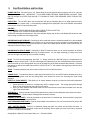
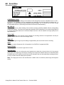
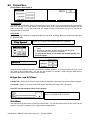
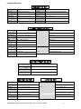
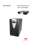
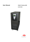
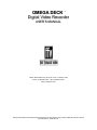
2 REAR PANEL DESCRIPTION Rear Panel Illustration (Single Shown) 1 1 CHANNEL 1 - INPUTS TIME CODE 5 CH1 IN AUDIO 1 COMPOSITE Y R-Y OUT AUDIO 2 B-Y 2 3 OUT OUTPUT REF RS-422 OUT 6 Channel 1 SCSI 2 4 IN IN 7 1. ANALOG VIDEO INPUTS - Composite and Component (Y, R-Y, B-Y) input BNC connectors. 2. ANALOG VIDEO OUTPUTS - Composite and Component (Y, R-Y, B-Y) output BNC connectors. 3. RS-422 - MACHINE CONTROL (DB9 CONNECTOR) - This connector is for controlling the Omega Deck from an external RS-422 device or via PC (utilizing supplied RS-232 to RS-422 adapter). 4. SCSI II - This connector is for adding external drives to the Omega Decks internal SCSI drive chain. If an external device is not used than a terminator should be connected here (no external terminator ever required for removable drive version of Omega Deck). 5. TIME CODE IN AND OUT - RCA connectors for longitudinal time code (LTC). 6. AUDIO INPUT AND OUTPUT - Balanced audio XLR connectors. 7. REFERENCE BNC - Use this connector for genlock. The signal must conform to broadcast specifications which is RS-170 for NTSC. Composite video or black burst are acceptable. DO NOT connect nonstandard signals to the Omega Deck, or the picture WILL distort. 8. SDI- In the case of SDI, the IN/OUT connectors would take the place (spacing) of the three component inputs. In this configuration, the deck will set up with composite in/out, SDI in/out, and component out. Rear Panel Illustration (Dual Shown) 2 Omega Deck Manual, Fast Forward Video, Inc. – Revised 1/06/04 5