1
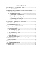
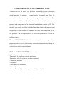
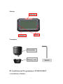
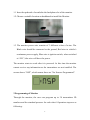
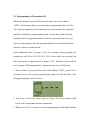
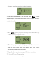
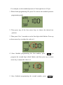
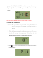
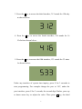
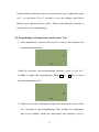
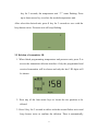
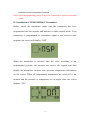
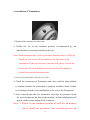
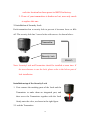
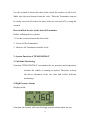
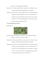
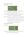
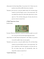
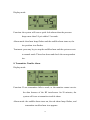
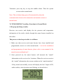
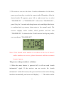
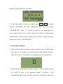
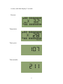
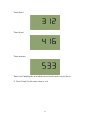
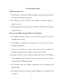
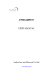
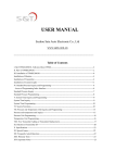
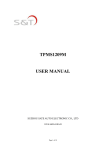
TPMS1209T08-T
USER MANUAL
Suzhou Sate Auto Electronic Co., Ltd
www.sate.com.cn
Table of Contents
I. TPMS1209T08-T, Full-time Direct TPMS---------------------------------------2
II. Parts of TPMS1209T08-T ------------------------------------------------------------2
III. Installation and Programming of TPMS1209T08-T Monitor-------------3
1. Installation of Monitor------------------------------------------------------------3
2. Programming of Monitor--------------------------------------------------------4
2.1Programming of Transmitter ID------------------------------------------5
2.2 Standard Pressure Programming----------------------------------------6
2.3 System Time Programming----------------------------------------------- 8
2.4 Programming of Pressure Unit -----------------------------------------10
2.5 Deletion of Transmitter ID-----------------------------------------------11
IV. Installation of TPMS1209T08-T Transmitter---------------------------------12
1. Installation of Transmitter---------------------------------------------------------12
2. Installation of Security Lock------------------------------------------------------14
V. System Function of TPMS1209T08-T ------------------------------------------15
1. Full-time Monitoring --------------------------------------------------------------15
2. High Pressure Alarm ---------------------------------------------------------------15
3. Low Pressure Level 1 Alarm ----------------------------------------------------16
4. Low Pressure Level 2 Alarm-----------------------------------------------------16
5. Low Pressure Level 3 Alarm-----------------------------------------------------17
6. High Temperature Alarm ----------------------------------------------------------18
7. Quick Leak Alarm -------------------------------------------------------------------18
8. Transmitter Trouble Alarm--------------------------------------------------------19
VI. TPMS1209T08-T Auxiliary Functions in Normal Mode-----------------20
Alarm Record Inquiry------------------------------------------------------------------20
VII. Specifications -------------------------------------------------------------------------22
VIII. Frequently Asked Questions ----------------------------------------------------24
IX. Warranty Term -------------------------------------------------------------------------28
X. Important Notes ------------------------------------------------------------------------29
1
I. TPMS1209T08-T, FULL-TIME DIRECT TPMS
TPMS1209T08-T is direct tire pressure monitoring system for trucks
which includes 1 monitor, 1 smart booster (optional) and 2 to 38
transmitters and it can support monitoring of up to 38 tires. The
transmitter can be screwed onto the tire valve and then senses the
pressure and temperature all the time and send data to monitor by RF. The
monitor can receive and deal with the data, then display the pressure and
temperature on the screen. The monitor can issue different alarms if the
tire pressure is at an improper level, so as to notify the driver to treat the
problem timely.
Through TPMS1209T08-T, the driver can keep the tire running under a
proper pressure so as to avoid excess gasoline consumption and keep the
vehicle in an easily controlled state.
II. Parts of TPMS1209T08-T
1 Monitor
Transmitter for each tire position purchased
Transmitter lock for each tire position purchased
1 Mounting Bracket
2 Wrenches
4 3M Dual Lock Fasteners
1 User Manual
1 Smart Booster (Optional and purchased independently)
2
Monitor
Alarm Lamp
Button
LCD Display
Transmitter
Transmitter
Security lock
III. Installation and Programming of TPMS1209T08-T
1. Installation of Monitor
3
1.1 Insert the pedestal of acetabulto the backplane slot of the monitor.
1.2 Choose a suitable location on dashboard to install the Monitor.
1.3 The monitor power wire consists of 3 different colors of wires. The
Black wire should be connected to the ground, Red wire to vehicle’s
continuous power supply, Blue wire to ignition switch, when switched
to “ON”, blue wire will have the power.
The monitor starts to work after it is powered. At this time the monitor
cannot receive any information as the transmitters are not installed. The
screen shows “NSP”, which means there are “No Sensors Programmed”.
2 Programming of Monitor
Through the monitor, the user can program up to 38 transmitters ID
numbers and the standard pressure for each wheel. Operation steps are as
following:
4
2.1 Programming of Transmitter ID
When the monitor is powered for the first time, the screen shows
“NSP”, which means there is no transmitter programmed into it. If the
user wants to program a new transmitter into the monitor, the operation
should be finished in programming mode. At this time, make sure the
transmitter to be programmed has not been screwed onto the valve yet.
Screw on transmitters until the programming has been finished and the
monitor returns to normal mode.
Each transmitter has 4 groups of ID, for example when program the
transmitter with ID of 001 001 001 158 to front right tire position, the
user only needs to input the last 3 digits “158”. Monitor will record the
rest 3 groups of ID automatically. Operation steps are as following:
1. After monitor is powered, the screen will display “NSP”, press P for 3
seconds to access the system programming mode, the first interface is for
ID programming as shown below:
2. Press any of the four arrow keys to choose the tire position which
needs to be programmed with a transmitter.
3. Then press S for 3 seconds to start programming and the digit flashes,
5
then press up or down arrow key to adjust the number.
4. Once finish programming of the first digit, press
→
to start
programming the second digit which flashes. Press up or down arrow key
to adjust the number.
5. Press
→
again to program the third digit which flashes. Press up
or down arrow key to adjust the value.
6. When finish programming these 3 digits, press S for 3 seconds to save
with the screen flashes twice, beep buzzes twice. Then it will
automatically switch to next tire position.
7. Repeat the above operations to program ID of other transmitters.
2.2 Standard Pressure Programming
6
For example, set the standard pressure of front right tire to 105 psi:
1. When finish programming ID, press P to access the standard pressure
programming mode.
2. Then press any of the four arrow keys to choose the desired tire
position.
3. Then press S for 3 seconds to set the first digit which flashes. Press up
or down arrow key to adjust the value to 1.
4. Once finished programming the first number, press
→
to
program the second digit which flashes and then press up or down
arrow key to adjust the value to 0.
5. Once finished programming the second number, press
7
→
to
program the third digit which flashes and then press up or down arrow
key to adjust the value to 5. Then press S for 3 seconds to save the
setting.
Note: The default standard pressure is set to 100 psi in factory.
2.3 System Time Programming
Function: The system clock was preset in the factory. It is the base of
the alarm record, user can check the current date and time as
follows:
1. When finish programming the standard pressure, press P to access
interface for inquiry and programming of time/date, the first
interface displays the year, 1 07 stands for the year 2007:
2. Press ↓ key to access the second interface, 211 stands for November
as shown below:
8
3. Press the ↓ key to access the third interface, 312 stands for 12th day
as shown below:
4. Press the ↓ key to access the fourth interface, 416 stands for 16
O’clock as shown below:
5. Press the ↓ key to access the fifth interface, 533 stands for 33 mins.
As shown below:
Under any interface of system time inquiry, press S for 3 seconds to
start programming. For example change the year to “09”, under the
year interface, press S for 3 seconds, the second digit flashes, press up
or down arrow key to adjust the value. Then press → key, the third
9
number flashes, then press the up or down arrow key to adjust the value
to“9”. At last press S for 3 seconds to save the change with screen
flashes twice and beep buzzes twice. Then it automatically switches to
next interface for programming.
2.4 Programming of Temperature and Pressure Unit
1. After program the system time, press P to access the pressure unit
programming interface.
Under the pressure unit programming interface, press S key for 3
seconds to adjust the programming. Press ↑ or
↓
key to select
the desired pressure unit.
2. Under any interface displaying temperature or pressure, press S key
for 3 seconds to start programming. Take change the temperature
unit as an example: under the temperature unit interface, press S
10
key for 3 seconds, the temperature unit “℃” starts flashing. Press
up or down arrow key to select the needed temperature unit.
After select the desired unit, press S key for 3 seconds to save with the
beep buzzes twice. Pressure unit will stop flashing.
2.5 Deletion of transmitter ID
1. When finish programming temperature and pressure unit, press P to
access the transmitter deletion interface. Only the programmed and
received transmitter will be shown and only the last 3 ID digits will
be shown:
2. Press any of the four arrow keys to locate the tire position to be
deleted.
3. Press S key for 3 seconds to delete with the screen flashes twice and
beep buzzes twice to confirm the deletion. Then it automatically
11
switches to next transmitter location.
Note: After programming, press P key for 3 seconds to return to normal
mode.
IV. Installation of TPMS1209T08-T Transmitter
Before install the transmitter, make sure the transmitter has been
programmed into the monitor and monitor is under normal mode. If no
transmitter is programmed or transmitter signal is not received after
program, the screen will display “NSP”.
When the transmitter is screwed onto the valve according to the
programmed position, the monitor can receive the signals and then
display the transmitter location icon, pressure, temperature information
on the screen. When all programmed transmitters are received by the
monitor and the pressure or temperature are in proper state, the screen
displays “ON”.
12
1. Installation of Transmitter:
1. Remove the current tire valve cap.
2. Inflate the tire to the standard pressure recommended by the
manufacturer or pressure needed by the user.
Note: Each transmitter has a lock to prevent it becomes loose or falls off.
Install the lock or not will not influence the functions of the
Transmitter. If the user chooses to use the lock, please refer to the
below part of lock installation. Security Lock and Transmitter
should be installed at the same time.
3. Screw the transmitter onto the tire valve.
4. Check the connection of Transmitter and valve with the soap solution
to confirm whether the transmitter is properly installed, check if there
is air leakage caused by the installation or the seal of the Transmitter.
5. Once screwed onto the tire, transmitter can sense the pressure inside
the tire and transmit the data to the monitor, and the information will
appear on the screen within about 6 minutes.
Note: 1. Please set the standards pressure of each tire on monitor
before install the transmitter. The standard pressure for
13
each tire location has been preset to100PSI in factory.
2. If one of your transmitters is broken or lost, user only needs
to replace this one.
2. Installation of Security Lock
Each transmitter has a security lock to prevent it becomes loose or falls
off. The security lock has 3 screw holes with screws. As shown below:
Transmitter
Security lock
Note: Security Lock and Transmitter should be installed at same time. If
the user chooses to use the lock, please refer to the below part of
lock installation.
Installation step of the Security Lock
1. First connect the meshing parts of the Lock and the
Transmitter to make them an integrated part, and
then screw the Transmitter together with the Lock
firmly onto the valve, as shown in the right figure.
2. Lock the Transmitter
14
Use the wrench to fasten the three bolts inside the sockets on the Lock.
Make sure they are fastened onto the valve. Then the Transmitter can not
be easily screwed off unless the three bolts are screwed off by using the
wrench.
How to inflate the tire with a locked Transmitter
Before inflating the tire, please
1. Use the wrench to loose the three bolts.
2. Screw off the Transmitter.
3. Remove the Transmitter and the Lock.
V. System Function of TPMS1209T08-T
1. Full-time Monitoring
Function: TPMS1209T08-T can monitor the tire pressure and temperature
whether the vehicle is running or parked. Therefore to keep
the driver informed of the tire state and realize full-time
monitoring.
2. High Pressure Alarm
Display mode:
Function: the system will issue the high pressure alarm when the tire
15
pressure is 25% higher than the standard.
Alarm mode: the alarm lamp flashes, high pressure warning icon, tire
position icon and the audible alarm turn on together.
Treatment: press any key to stop the audible alarm. The red alarm lamp
remains on and the display reverts to the normal mode. At
this time user should properly adjust the tire pressure to the
normal level. The red alarm lamp goes off only when the tire
pressure returns to the normal level.
3. Low pressure level 1 alarm
Display mode:
Function: the system will issue low pressure level 1 alarm when the tire
pressure is 12.5% lower than the standard.
Alarm mode: the alarm lamp flashes, low pressure level 1 alarm icon, tire
position icon and the audible alarm turn on together.
Treatment: press any key to stop the audible alarm. The red alarm lamp
remains on and the display reverts to the normal mode. At
this time the user should adjust the tire pressure to normal
level as soon as possible. The red alarm lamp goes off only
when the tire pressure returns to normal level.
16
4. Low pressure level 2 alarm
Display mode:
Function: the system will issue low pressure level 2 alarm when the tire
pressure is 25% lower than the standard.
Alarm mode: the alarm lamp flashes, low pressure level 2 alarm icon, tire
position icon and the audible alarm turn on together.
Treatment: press any key to stop the audible alarm. The red alarm lamp
remains on and the display reverts to the normal mode. The
user should slow down the vehicle and drive to a service
shop to inflate the tire. The red alarm lamp goes off only
when the tire pressure returns to normal level.
5. Low pressure level 3 alarm
Display mode:
Function: the system will issue low pressure level 3 alarm when the tire
pressure is 50% lower than the standard.
17
Alarm mode: the alarm lamp flashes, low pressure level 3 alarm icon, tire
position icon and the audible alarm turn on together.
Treatment: press any key to stop the audible alarm. The red alarm lamp
remains on and the display reverts to the normal mode. The
user should slow down the vehicle and replace the tire with a
spare tire. The red alarm lamp goes off only when the tire
pressure returns to normal level.
6. High Temperature Alarm
Display Mode:
Function: When the temperature around the transmitter equals or exceeds
90℃, the system will issue the high temperature alarm.
Alarm Mode: the alarm lamp and temperature value flashes, tire position
icon and the audible alarm turn on together.
Treatment: press any key to stop the audible alarm. The red alarm lamp
remains on and the display reverts to the normal mode. The
driver should slow down and properly cool down the tire.
The red alarm lamp goes off automatically when the
temperature returns to normal level.
7. Quick Leak Alarm
18
Display mode:
Function: the system will issue a quick leak alarm when the pressure
drops more than 2.8 psi within 12 seconds.
Alarm mode: the alarm lamp flashes and the audible alarm turns on, the
tire position icon flashes.
Treatment: press any key to stop the audible alarm and the system reverts
to normal mode. Then slow down and check the correspondent
tire.
8. Transmitter Trouble Alarm
Display mode:
Function: If one transmitter fails to work, or the monitor cannot receive
the data because of the RF interference for 20 minutes, the
system will issue a transmitter trouble alarm.
Alarm mode: the audible alarm turns on, the red alarm lamp flashes, and
transmitter trouble alarm icon appears.
19
Treatment: press any key to stop the audible alarm. Then the system
reverts to the normal mode.
Note: The red alarm lamp goes off automatically when the
communication between the transmitter and monitor returns to
normal state.
VI. TPMS1209T08-T Auxiliary Functions in Normal Mode
1. Hoop up and drop a trailer
Receiver can receive and display the tire pressure and temperature
information of the trailer wheels through the smart booster installed on
the trailer.
The process to hook up a trailer is as follows:
1. Make sure that receiver and smart booster have been installed and
programmed, receiver is in the normal mode.(As for the installation
and programming of smart booster, please refer to user manual of the
smart booster and hand tool.)
2. Once powered on, the smart booster will transmit the “match”
information to the receiver for 5 minutes. When the receiver receives
the “match” information, the screen switches to the “match interface”.
If they match successfully, screen will display the last 3 digits of ID,
trailer outline, wheel position start flashing, as shown below:
20
3. The receiver can save the latest 5 trailers information. At this time,
press up or down key to select the correct trailer ID number. After the
desired trailer ID appears, press left or right arrow key to select
“TRAILER ON” or“TRAILER OFF”. After select “TRAILER ON”,
press S key for 3 seconds with beep buzzes twice and digits flash twice
to confirm hook up success, then return to the normal mode. The
receiver displays trailer outline, wheel position and the icon
“TRAILER ON”. As shown below. If don't want to hook up any trailer,
user can choose “TRAILER OFF”.
Note: If the desired trailer number is not shown in the list of latest 5
trailer numbers on receiver, please disconnect and then reconnect
booster’s power.
The process to drop a trailer is as follows:
1. When the smart booster is powered off, it will not send “match
information” signal. If the receiver can not receive the “match
information” within 90 seconds, the system will access the trailer deleting
interface automatically, and screen will display“- - -”. The trailer outline
21
and trailer wheel positions will flash.
2. If the user wants to delete the trailer, press
→
←
to switch
between “TRAILER ON” and “TRAILER OFF”. If user chooses
“TRAILER OFF”,press S key for 3 seconds to save with beep buzzes
twice, figures flash twice, and the system will return to normal mode
automatically as shown below. If user does not want to delete the trailer
information, choose “TRAILER ON”.
2. Alarm Record Inquiry
1. Under normal mode or pressure inquiry interface, press P and S at the
same time for 3 seconds to access the alarm record inquiry interface.
The screen with “0” is the most recent alarm record, as shown below:
2. Under alarm record inquiry interface, Press → key to check through
the record. If there is no operation within 3 seconds, it will
automatically display the record data (pressure, temperature and time)
22
in turn, each data displays 3 seconds.
Pressure.
Temperature
Time (year)
Time (month)
23
Time (date)
Time (hour)
Time (minute)
Then it will display the next alarm record in the same way as above.
4. Press P and S at the same time to exit.
24
VII. Specifications
Monitor
Modulation Type: FSK
Mid-frequency: 434.1 MHz
Receiving Sensitivity: -105 dBm
Input Voltage: 12V / 24V
Current: < 60mA
Operating Temperature: -30℃~70℃
Storage Temperature: -30℃~75℃
Transmitter
Modulation Type: FSK
Mid-frequency: 434.1 MHz
Transmitting Power: 0 dBm
Input Voltage: 3.6V (Battery)
Static Current: < 0.7uA
Operating temperature range: -40℃~125℃
Storage temperature range: -40℃~125℃
Transmitter weight: about 24 g
VIII. Frequently Asked Questions
25
1. Why do I need to check the tires periodically with the TPMS
system installed?
Periodic check of the tire can keep the driver aware of the tires conditions
and ensure driving safety.
2. Pressure alarm frequently occurs.
The user can check if the standard pressure is suitable or not. If the
standard pressure is too high or too low, re-set the standard pressure as
per instructions on page 7 of USER MANUAL.
3. How long can the transmitter battery work?
The transmitter battery can last about 5 years under normal conditions.
4. How to deal with the transmitter trouble alarm issued by monitor?
If one transmitter fails to work, or the monitor cannot receive the
signals for 20 minutes because of the RF interference, the system will
issue a transmitter trouble alarm. Once there is no interference, the
system shall recover normal performance.
5. Why the temperature sensed by the transmitter is quite different
from the actual value?
The temperature sensed by the transmitter is the environment
temperature, not that inside the tire.
When vehicle runs the temperature around the transmitter will rise.
When there is high temperature alarm, please check if the tire is under
abnormal condition which causes the wheel rim becomes very hot, and
26
lower its temperature in time.
6. The monitor displays nothing or abnormal code.
Please check the power connection.
7. When connected with vehicle’s continuous power supply, will the
power of storage battery be used up if the vehicle parks for a long
period?
The current draw of the monitor is only 50 mA under normal state and
this can be ignored. However, if the vehicle will not be used for 2 or 3
months, the storage battery might be used up and the vehicle cannot be
started. So we suggest the user remove the storage battery if the vehicle
will not be used for a long period.
27
IX. Warranty Terms
Valid Warranty Card
1. The Warranty Card must be filled completely, signed by and sealed by
the authorized distributors of Sate.
2. The Warranty Card is valid in the countries or regions where the
purchase occurs.
3. The Warranty Service requires user to offer the Warranty Card and the
original invoice.
Warranty Condition, Responsibility and Limitation
1. The product warranty period is one year and is subject to the time
marked on the invoice.
2. Any damages or faults due to improper use are not involved in the
warranty commitment.
3. Users are not allowed to open, repair and refit the products by
themselves, otherwise the warranty service will be invalid.
4. Injecting chemicals such as leak-proof glue into the tire will damage
the Transmitters, and, affect the system operation. Do not use such
articles after the TPMS is installed.
5. The warranty does not include replacement of the enclosure and
display panel.
6. The warranty does not cover the product damage due to abrasion and
corrosion.
28
X. Important Notes
1. The Warranty Card must be filled completely and its number shall be
quoted whenever the user requires the service.
2. Please inform Sate in case that the telephone number or address on the
Warrant Card is changed.
3. The warranty responsibility is subject to the conditions and limitations
specified in the User Manual.
4. TPMS1209T08-T monitor should be connected with the continuous
power supply and installed by the professional. S&T is not
responsible for the vehicle circuit damage or accident caused by
wrong installation or improper use of the system.
5. S&T TPMS can perform full-time monitoring function, but cannot
avoid all unexpected accidents.
29