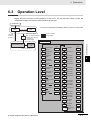
1
7 User Calibration
7-3
Thermocouple Calibration
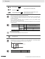
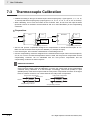
• Calibrate according to the type of thermocouple: thermocouple group 1 (input types 5, 7, 11, 12, 15,
19, and 20) and thermocouple group 2 (input types 6, 8, 9, 10, 13, 14, 16, 17, 18, 21, 22, 23, and 24).
• When calibrating, do not cover the bottom of the Controller. Also, do not touch the input terminals
(terminals 5 and 6 on the E5CC and terminals 23 and 24 on the E5EC/E5AC) or the compensating
conductors.
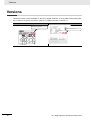
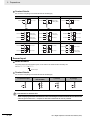
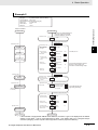
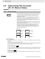
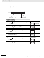
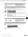
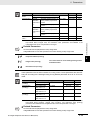
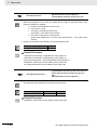
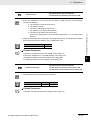
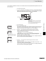
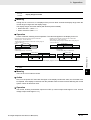
z Preparations
11
STV
E5CC
1
Input power supply
STV
E5EC/E5AC
Input power supply
12
−
+
5
6
Cold junction
compensator
0°C/32°F
2
−
23
+
24
Cold junction
compensator
0°C/32°F
Compensating conductors
Compensating conductors
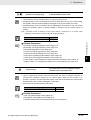
• Set the cold junction compensator designed for compensation of internal thermocouples to 0°C.
Make sure that internal thermocouples are disabled (i.e., that tips are open).
• In the above figure, STV indicates a standard DC current/voltage source.
• Use the compensating conductor designed for the selected thermocouple. When thermocouples R,
S, E, B, W, or PLII or an infrared temperature sensor is used, the cold junction compensator and the
compensating conductor can be substituted with the cold junction compensator and the
compensating conductor for thermocouple K.
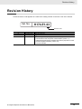
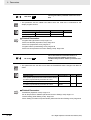
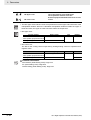
Additional Information
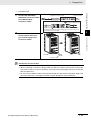
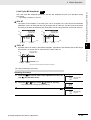
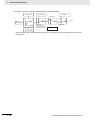
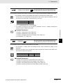
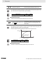
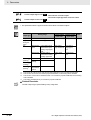
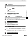
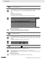
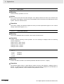
Connecting the Cold Junction Compensator
Correct process values cannot be obtained if you touch the contact ends of the compensating
conductor during calibration of a thermocouple. Accordingly, short-circuit (enable) or open
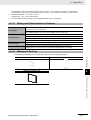
(disable) the tip of the thermocouple inside the cold junction compensator as shown in the figure
below to create a contact or non-contact state for the cold junction compensator.
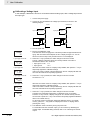
Cold junction compensator
Short-circuit
E5@C
0°C/32°F
Compensating conductor
7-4
Cold junction compensator
E5@C
0°C/32°F
Open
Compensating conductor
E5@C Digital Temperature Controllers User’s Manual (H174)