1
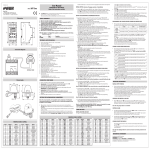
Mod.Tlc-solar Tlc-solarisasystemfortheremotecontrolofphotovoltaicsystemsbysendingtext messagesorringtonestocertifiedusers. TheheartofthesystemismadeupofGWIsolarwhichcomparesthesignalcoming fromtheproducedenergymeteronthesystemandthatcomingfromtheradiation sensortocheckifproductioncomplieswiththeradiationconditions,thusenablingany malfunctionstobefoundintime.Anyfallinproductionisautomaticallycommunicated bythesystembysendingtextmessagestotheselectedusers.Furthermore,GWIsolar hasanotherinputavailableforconnectingaburglaralarmandtwooutputswhichcanbe activatedmanuallyorfollowinganalarm. I - 32032 Feltre (BL) • Via Camp Lonc, 16 Tel +39 0439 80638 • Fax +39 0439 80619 e-mail: [email protected] - web site: www.vemer.it GWIsolarTECHNICALCHARACTERISTICS Powersupply:12VACfromTMC10/12asshowninthediagram Absorption:100mAmax Output -twobistablerelayswithchange-overcontact −powercircuitbreaker:8(5)A/250VAC SignallingLEDs: -Tworedledsforoutputrelaystatussignalling -Twogreenledsfordigitalinputstatussignalling −Multicolourledsfordevicestatussignalling GSMQuadBandmodule(900-950-1800-1900MHz) SMA-Fconnectorforexternalantennaprovidedwith3mlongcable Workingconditions:0÷50°C/10÷90%non-condensing Degreeofprotection:IP40 Insulationclass:II Container:4DINmodules Backupbatterycapacity:approximately1hour SAFETYWARNINGS During the installation and operation of the device observe the following instructions: 1) The instrument must be installed by a qualified person 2) The instrument must be installed and activated in compliance with current electric systems standards 3) After installation, inaccessibility to the connection terminals without appropriate tools must be granted 4) Do not use the instrument for purposes other than indicated 5) The device must be installed in a electric closed panel well protected 6) A two-pole disconnect device shall be provided as part of the building installation 7) A protection device against over-currents should be installed in the electrical system, upstream of the device 8) Carefully respect the wiring diagrams to install the instrument 9) Before accessing the connection terminals, verify that the leads are not live 10) Do not power or connect the instrument if any part of it is damaged 11) The use of a GSM device can cause interference with the functioning of electronic devices non-screened from radiofrequency signals (electromedical devices, pacemakers, hearing aids etc.) 12) In case of fault, do not service the device yourself but contact the after-sales service 13) The instrument is aimed for use in place with over-voltage category III and pollution degree 2, as per standards EN 60730-1. GWIsolarDEVICESTATUS Thedevicestatusissignalledbytheled : Code KT018000 KT018500 KT021500 SWITCHEDOFFnopowersupplytodevice REDBLINKINGsimcardnotinsertedorpinactive REDSTEADYinsufficientgsmfield GREENSTEADYinitialisinginstrument/networksearch GREENBLINKINGgsmnetworkconnection GREENBLINKINGVELOCEcommand(ringtoneortextmessage)incoming GREEN/REDBLINKINGactiveprogrammingmode YELLOWBLINKINGgsmnetworkconnectionbutbatteryflat QUICKLYBLINKINGREDmodemerrororfailure(ifstillflashing) Note:blinking=1lamp/second quicklyblinking=5lamps/second Model Tlc-solar230 Tlc-solar400 Tlc-solar400TA commandsexecutedwillonlybethosewhosereplyiscontainedinastandard textmessage(160characters).Toenternumberswiththedecimalseparator, youneedtouseafullstop. • Preparation GSMCOMMUNICATIONINTERFACE Readallinstructionscarefully Vemer S.p.A. Description Kittelecontrolforsingle-phasesystemsupto15kW Kittelecontrolforthree-phasesystemsupto69kW Kittelecontrolforthree-phasesystemsupto690kW TheTlc-solarismadeupof: –GWIsolarcontrolunit(codeVE326500) –radiationsensor(codeVE327300) –TMC10/12transformer(codeVN314100) –ADR-D230D63energymeter(codeVE035200)(single-phasesystems)or ENERGY-400D90(codeVN984100)(three-phase69kWsystems)orENERGY-400DPWRi (codeVE120200)(three-phase690kWsystems) isablethepincoderequestfromthesimcardwhichwill D beinsertedintotheGWIsolar. Thestructureofareplytoacommandissimilartothecommanditself,withthe additionofthe“=”symboltoindicatethecurrentstatus.Forexample: I nsertthesimcardintotheslot(typepush-push).The directionofinsertionprovidesthatthebevelofthesim cardgoesinsideintheleft. OUTKEYBLOCKOUTKEY=BLOCK MODIFYPULSEWEIGHTS(foradminonly) ote:therechargeablesimneedsaperiodical N minimumtop-up(usuallyonceayear)inorderto bevalid.Checkwithyouroperatorabouttherenewalmode. BydefaultthepulseweightthattheGWIsolarreceivesfromtheenergymeter is0.1kWh.Ifitisnecessarytomodifythisvalueusethecommand: WIMP[pulseweight]where ote.Thesimcardinsertionandremovaloperationsshouldbecarriedoutwith N theinstrumentswitchedoffandnotpoweredup(pleaseseetherelativechapter forswitchingofftheinstrument). [pulseweight]newvaluetobegiventoapulse Inthecaseofdecimalvalues,useadecimalpointasaseparator. ToreadthecurrentvalueusethecommandWIMPwithnoparameters. Forexample: WIMP1 givesthevalue1.00kWhtoeachpulse WIMP0.1 givesthevalue0.10kWhtoeachpulse WIMP restoresthecurrentweightofthepulse MEMORISINGSTAFFNUMBERS(foradminonly) I tispossibletocreateatelephonebookcontainingupto10telephonenumbers(staff numbers)whichcan: –receivetextmessage(orringtone)incaseofalarms –receivetextmessagewiththeproducedenergyandtheinstantaneouspower followingaringtone –receivetextmessagefollowingascheduledevent. • Wiring –Attachtheradiationsensornearthephotovoltaicpanelswiththesameinclinationand connectittotheanaloginputoftheGWIsolar(thewhite/blackwiretoterminal14,the blackonetoterminal12). Caution:thesensormustbepositionedsothatthesolarraysdonothititbeforetheyhit thepanels,inordertoavoidfalsealarmsbeingsent,forexample,atdawn. –connecttheenergymeterdownfromthesolarproductioninverter,andconnectthepulse outputmeteratinput1oftheGWIsolar(DIG1-terminals10and13) –connectanyburglarsystem(presencesensors,microswitches,...)atdigitalinput2 GWIsolar(DIG2-terminals11and13) –connectthetransformertotheGWIsolarandthenetworkvoltage. Foradetaileddescriptionoftheconnections,pleaseseethediagram“Connectiondiagram”. ncethekithasbeenpoweredup,theled oftheGWIsolarrelatingtothedevicestatus O willremainonsteadygreenforaround30seconds,thiswillendwhenitstartsblinkinggreen onceasecond,signallingthecorrectreceptionofthegsmnetwork.Ifthisshouldnotbethe case,pleaseseetheoverview“Devicestate”. • Basicconfiguration Toaddastaffnumber: onsistsindefiningtheadminnumber,whichhasfullcontrolofthesystem(usuallyforthe C owner)towhomalarmmessagesaresent –sendthefollowingcommandfromtheadminnumber: STAFF[index][telephonenumber]where, MEMORISINGADMINISTRATIVENUMBERS –pressthe“1”keyoftheGWIsolarfor5secondsuntiltheled startsblinkingred/green alternately –carryoutaringtonewiththenumberwhichyouwanttosetasadminnumber. Thecallerwillreceiveaconfirmationtextmessagethatthishastakenplace. [index] positioninthestafftelephonebookwherethenewnumberissaved [telephonenumber] numbertobeaddedtothetelephonebook orexample,toinsertthestaffnumber392123445inposition4: F STAFF4392123445 I tisalsopossibletoenterseveralstaffnumbersusingonecommandonly: Forexample,ifyouwanttoinsertthenumbers044177458,392123445and12345678in positions2,4,and7: STAFF20441774584392123445712345678 Note:afterhavingsettheadminnumber,theGWIsolarwillcarryoutaselfcalibrationprocedure,duringwhichtimeitanalysesalltheparametersofthe systemwhereitisinstalled.TocarryoutthisoperationtheGWIsolarneedsafew hoursofsunshine. Attheend,theadminnumberwillreceiveatextmessageandfromthenon,it willbegintomonitortheproducedenergy. OPERATION • Defaultsettings Radiation sensor kW/h Produced energy unidirectional meter Bidirectional produced/absorbed energy meter GWI SOLAR antitheft antitheft sensor + Generator panel GWI SOLAR General panel hefactorysettingsforthekitprovidefortheadminnumbertoreceiveaseriesoftext T messages: –sendamonthlytextmessagetotheadministratorwiththevalueofproducedenergy –sendatextmessagecontainingthevalueofproducedenergyandinstantaneouspower followingaringtone –forwardmessagesdestinedtotheGWIsolarandnotrecognisableascommands(for exampleatextmessagefromatelephoneserviceprovider)totheadministrator Furthermoreatextmessageissenttotheadministratorincasesof: –radiationsensormalfunctionalarm –nometerpulsesalarm –productionbelowthresholdalarm –noelectricalnetworkorbufferbatteryflatalarm Foreachofthealarmslistedabove,analarmreturntextmessageissent. BydefaultthepulseweightreceivedfrominputDIG1is0.1kWh(modifiable). Tocancelastaffnumber,usethewordNULL. Forexample,ifyouwanttocancelthestaffnumber4,leavingthepositioninthe telephonebookempty: STAFF4null TohaveacompleteoverviewofthetelephonebookwriteSTAFFwithoutparameters. Note:theadminnumberisinsertedbydefaultasstaffnumberposition1. ALARMSMANAGEMENT Thepossiblealarmsourcesarereportedinthefollowingtable: Three-phase network max 690 kW Three-phase network max 69 kW Single-phase network max 15 kW ENERGY-400D PWRi ENERGY-400 D90 ADR-230 D63 GWI SOLAR TMC 10/12 OUT 2 N sensor + L1 L1 L2 L3 0,1 kWh / pulse sensor – I3 L1 L2 L3 1 kWh / pulse 230 V ~ N L1 L2 L3 ENERGY + I2 L3 ENERGY – I1 L2 OUT 1 N ENERGY + L1 ENERGY – ENERGY + ENERGY – N N 12 V ~ 0,1 kWh / pulse I nthisphaseitispossibletoaddothertelephonenumbersaswellastheadministrator's (staffnumbers)wherealarmsignalswillbesent,bychoosingforeachnumberwhichtypeof alarmtosend. Furthermore,itispossibletomodifytheautomaticforwardingplanformessageswith plannedsettimesoractivateautomaticswitchingfunctionforanoutputfollowingaspecific alarmcondition. STRUCTUREOFACOMMANDTEXTMESSAGE Thegeneralstructureofatextmessageisasfollows: [password][separator][command][separator][parameter1][separator]..[parameterNo.] where: [password] [separator] [command] [parameter..] hepasswordfieldmaybeomittedifthecommandisgivenbyaregistered T number.Severalcommandsmaybeincludedinonetextmessage.Inthiscase,the numericalfieldofamaximumof8figures comprisedofoneormorespacecharacters commandrecognisedbythedevice seriesofparametersrelativetothecommand Table1 Typeofalarm DIG2 RDIG2 LOWBAT POWERF RPOWERF SCHED LUX RLUX IMP RIMP DELTA RDELTA POK RPOK • Advancedconfiguration ENERGY + sensor – Burglar alarm kW/h Thestaffnumbersareidentifiedprogressivelyfrom1to10. Thefirst5staffnumbersarealreadyassociatedbydefaultto5welldefinedalarm situations(pleasesee“Alarmsmanagement”)eveniftheycanbemodified. Inverter CONNECTIONDIAGRAM ENERGY – • • • • • • • • • • • INSTALLATION Usermanual V3IS00546-020-042011 Alarmdescription Alarmfromdigitalinput2 Alarmreturnfromdigitalinput2 Lowbatteryalarm Nonetworkalarm Alarmreturnfornomains Messageforperiodicforwarding Radiationsensormalfunction Alarmreturnradiationsensor Invertermalfunction Alarmreturninvertermalfunction Alarmenergyproductionlowerthanpredicted Alarmreturnenergyproduction ProductionexceedsthethresholddefinedwithSETPOK Alarmreturnenergyproductionabovethethreshold Itispossibletodefinewhichtypesofalarmsaresenttoeachstaffnumberandinwhich format(textmessageorringtone).Thefirst5staffnumbersaresetasfollows: Table2 Number STAFF1 STAFF2 STAFF3 STAFF4 STAFF5 Communicationsreceived Eachalarmevent Scheduledeventonly:SCHED Alarmsonly:LUX/RLUX,IMP/RIMP,DELTA/RDELTA Burglaralarmonly:DIG2/RDIG2 Noelectricalnetworkonly:POWERF/RPOWERF,LOWBAT Mode Textmessage Textmessage Textmessage Textmessage Textmessage To define the behaviour of other staff numbers or modify the behaviour of the pre-set ones, use the command: SENDALARM [type of alarm] [recipient][type of signalling]...[recipient] [type of signalling] [type of alarm] (please see table 1) [receiver] index of a staff number [signal type] SMS to receive a message, RING a ringtone Some examples: SENDALARM DIG2 1 SMS 2 RING 3 RING when there is an alarm on digital input 2, it sends a text message to contact staff member 1 and a ring tone to staff members 2 and 3 SENDALARM RPOWERF 2 SMS 6 RING when there is an alarm return due to no power supply an alarm text message is sent to staff member 2 and a ring tone to staff member 6 SENDALARM with [alarm type] displays the alarm warning parameters for the type of selected alarm Example: by sending the command SENDALARM DIG2 the device responds with DIG2=1M,2R,-,-,-,-,-,-,-,-, which means: send a text message to STAFF 1 and RING STAFF 2 if there is an alarm on Digital 2 Note: a new setting SENDALARM for a given type of alarm will overwrite the present one, for which it is necessary to indicate all the receivers of the alarms in one single command. NB: to cancel a SENDALARM setting, enter ‘0’ as the recipient. Example: SENDALARM DIG2 0 cancels the send alarm settings for DIG2 DIG2=-,-,-,-,-,-,-,-,-,-, If you have chosen to send alarms ringing through phone (see control sendalarm) you can set the length of the ring with the command: MAXRING [number] where [number] duration of the ringing in seconds (values between 0 and 255). By default, the duration of the ringing is 15 seconds. • Planned message sending function (for admin only) The instrument is set by default to send to the admin number on a monthly basis (and to the staff member 2 if defined) a text message with the value of produced energy. The SCHEDTIME and SCHEDTXT commands enable the period and the text of the message to be modified, respectively. SCHEDTIME [period] [offset start] where [period] [offset start] interval expressed in hours between one forwarding and another. start delay expressed in minutes For example: SCHEDTIME 24 15 send text message every 24 hours, the first in 15 minutes SCHEDTIME 260 60 send text message every 15 days, the first in one hour SCHEDTIME 0 SCHEDTXT [text] where [text] he text can contain a few special characters (symbols) which indicate the meter or T pulse meter values . These characters are solved by the instrument when the message is sent. For example: SCHEDTXT Produced energy #P1 kWh The text that will be sent could be “Energy produced 32 kWh” (with the value of meter P1 at 32) disable sending text message that will be sent The possible symbols are the following: Table 3 Tag #PT1 #P1 #P1R #D2 #O1 #O2 #CKS #CK Description pulse meter total (not zeroable) associated with digital input 1 pulse meter associated to digital input 1 pulse meter associated to digital input 1 with auto reset after forwarding digital input 2 status. In the message are the words: OPEN/LO or CLOSE/HI Output status 1. In the message are the words: ON or OFF Output status 2. In the message are the words: ON or OFF date and time of the forwarding of the last scheduled event current date and time If tag #P1 or #P2 are followed by a numeric value this is used as a multiplicative factor for the meter display. Example: SCHEDTXT Energy produced today #P1 1.34 kWh The value of the pulse meter is shown as multiplied by 1.34 and on the forwarded message in place of #P1 1.34 will be a number obtained by multiplying 1.34 by the value of the pulse meter associated with digital input1. NB: The number of decimal numbers is the same as the multiplier, in the case of previous example 2 NB: Each tag must be separated by at least 1 space inside the text. • Setting text message time (for admin only) It is possible to synchronise the date and time of the instrument with the command: RTCSMS To synchronise, the instrument reads the date and time in the received text message. It is also possible to link this command to the end of any command text message. For example: OUTALARM 2 OFF POWERF AUTO RTCSMS • Disable alarm messages (For admin only) Here is an example of a possible reply: OUT 1=ON OUT 2=OFF OUTRISP=ON RINGRISP=ON OUTKEY=TOGGLE meaning: output 1 ON, output 2 OFF, reply to enabled text message, reply to enabled ring tone, and change output status by pressing the relative key. • Modify output name (for admin only) To assign a name to the output that recalls the device to which it is connected, use the command: By default the number to which these text messages will be forwarded is the admin number. FORWARD OFF disables the function. The text messages which are forwarded to the specified number begin with the string “FW: ”. • Password management (for admin only) A text message sent from the admin number enables an instrument protection password to be changed, to be used in case you wish to send a command via text message from a disabled number. The command is: PASS For example: PASS 11223344 OUTTXT [output number] [output label] Some examples: OUTTXT 1 siren OUTTXT 2 valve OUTTXT 2 NO A string of a maximum of 10 characters with no spaces can be assigned as a name. If an alternative number for an output is defined, it is possible to use this name to indicate the output in the transmitted commands. For example: • Set threshold production valve ON 10 M By the command SETPOK you can set a threshold of production which, if exceeded, generates an alarm condition (alarm POK). In this way you can, for example, to switch a relay output when the power exceeds the threshold defined. The syntax is: inputs ManagEMENT It is possible to assign a name to the plant where the Tlc-solar is installed. In this way, each alarm text message or reply from the GWI solar will be headed by its given name. The command is: NAME [name system] SETPOK [threshold] [differential] where: [threshold]] represents the threshold in kW for alarm (POK) [differential] represents the hysteresis in kW for the return alarm (RPOK) A name with a maximum string of 20 characters can be assigned. To cancel write: NAME disabled For example: SETPOK 48 3.5 if the power produced is greater than 48kW the POK alarm is generated. When the power drops below 44.5kW (48-3.5) generates the alarm RPOK. GWI solar has two digital inputs whose status is signalled by two green leds (on input is short-circuited, off input open) and an analog input. The digital input DIG1 and the analog input are pre-set to be connected to the to the pulse output of the energy meter and the radiation sensor, respectively. Their behaviour cannot be modified. The digital input DIG2 can, on the other hand, be used with the discretion of the user, for example for connecting a burglar alarm system. In particular, digital input 2, can be connected to: You can check the number of text messages sent by the tool with the command: – signals from switches (ON/OFF) NSMS he instrument responds to the sender with a text message containing the number of T SMS sent (in count includes both sms sms alert that the response to commands). NSMS RESET lets you reset the counter. Command MSG manages enablement or not of forwarding messages to the staff. If MSG is OFF, the forwarding of all the messages or signalling of alarms managed by SENDALARM is disabled MSG ON MSG OFF Enables the transmission of messages and ringtones Disables the transmission of messages and ringtones OTHER FUNCTIONS • Set the alarm ringing time (for admin only) If there is a prolonged black-out with the battery going flat, it is necessary to repeat the command. If this command is not carried out, the instrument substitutes date and time with “--.--.-- --:--” assigns the name siren to output 1 assigns the name valve to output 2 restores the original name to output 2 activates output 2 (valve) for 10 minutes SETPOK NO remove the production threshold currently setting Note. The minimum measurable pulse length is 20ms (max frequency 25Hz). Note: The behaviour of the instrument in case of alarm conditions (POK, RPOK) is determined by commands OUTALARM (activation outputs) or SENDALARM (for sending sms or ring). • Set working mode for digital input 2 (for admin only) To set the working mode of the of digital input 2 use the command: • Automatic activation of an output on alarm conditions (for admin only) DIG 2 [working mode][timing alarm][unit], where It is possible to make the outputs switch automatically when there is one of following alarm: Table 4 [working mode] Type of alarm DIG2 LOWBAT POWERF POK [timing alarm] [unit] Example: DIG 2 CLOSE 20 M alarm if the status of input 2 remains closed for 20 minutes Alarm description Alarm from digital input 2 Low battery alarm No network alarm Production exceeds the threshold defined with SETPOK he output OUT2 is preset to switch for 30 seconds when there is an alarm at T digital input DIG2. The OUTALARM command enables the output behaviour to be modified. OUTALARM [output number][output status][cause of alarm][reset alarm mode] [output number] [output status] [cause of alarm] [reset alarm mode] Examples: OUTALARM 2 OFF DIG2 MAN 1 or 2 ON, OFF or DISABLE (please see table 4) MAN manual, AUTO at the end of an alarm condition or timing (maximum around 18 hours) with unit of measurement: s seconds, m minutes, h hours in the case of digital alarm 2 output 2 becomes OFF and remains in such status OUTALARM 1 OFF POWERF AUTO The output 1 goes OFF in case of no network and remains in this status until an alarm return OUTALARM 2 OFF DIG2 25 M output 2 goes OFF for 25 minutes in case of alarm on digital 2 OUTALARM 2 DISABLE function disabled • Setting the output status • Setting alarm text (for admin only) The output status can be piloted simply with the command: OUT [output number][output status][status holding time][unit of measurement], where − [output number] − [output status] − [permanence status time] − [unit of measurement] indicates the output to which reference is made (1 or 2) can assume the values ON, OFF maximum settable time (~130 years) (optional parameter) s seconds, m minutes, h hours (optional parameter) Some examples: OUT 1 OFF 10 S OUT 2 ON 12 S sets the relay 1 OFF for 10 seconds sets the relay 2 ON for 12 hours • Send text message to sender setting (for admin only) The instrument can be set to send the sender a text message of confirmation upon receiving a command via a text message. The command is • Count sms sent (for admin only) • Key operating mode setting (for admin only) By briefly pressing a key, the relevant output can be adjusted. Output behaviour can be defined with the following command: OUTKEY [functionality] with functionality that can assume the values: − TOGGLE when the key is pressed the output switches ON/OFF in a bistable manner − BLOCK disables the key functions (it will no longer be possible to access the programming mode) If the value is omitted, the current instrument status will be the reply. SWITCHING ON/SWITCHING OFF AND RESET THE GWI SOLAR To set the text which will be sent to the staff numbers, use command: DIGTXT 2 [alarm text] # [alarm return text] where • Turn off the instrument: [alarm text] [#] [alarm return text] Example: DIGTXT 2 burglar alarm # burglar alarm end string of max 60 characters of text that are sent to staff in case of alarm separator for alarm return text string of max 60 characters of text that are sent to staff in case of alarm return • Setting display To know the configuration of the DIG2 input use the command: DIGINFO Here is an example of a possible reply: DIG 2=OPEN ALARM CLOSE 10S which means: Digital input 2 open, alarm defined when input 2 remains closed for 10 consecutive seconds. ➢ Hold approximately 10 seconds for either the “1-SET” or “2” until all LEDs off. During the pression of the key, the output led blinks quickly and the led blinks green (or yellow) for the first 5 seconds and green/ red for the other 5 seconds. • Turn on the instrument without reset ➢ Press “2”. The LED will be green initially fixed and then begin to flashing green (or yellow), indicating the correct reception of the GSM signal. • Turn on the instrument with reset ➢ Press the “1-SET”. All LEDs will illuminate for a few seconds indicating that the reset occurred, after which the LED begins to flash green (or yellow) indicating the correct reception of the GSM signal. ote: The reset erases all data, settings and users stored tool and restore N factory defaults (see box on). Password Relay output status ADMIN number STAFF numbers STAFF behaviour 1÷5 Caller control Automatic call answer Reply to text message commands Forwarding unknown text messages No power supply warning ADVANCED INSTRUMENT MANAGEMENT The admin number can be modified by sending the following command (from the current admin number): ADMIN [new admin number] The new admin number will receive a confirmation text message. ote. If the admin number is lost, it can be changed only by forcing a reset, thus N losing all the previously enabled numbers. To avoid having to re-enter them manually, please refer to section “Sim card management”. • Sim card management (for admin only) The staff telephone numbers are saved in the memory of the device. In case of reset, this implies the loss of all the enabled utilities. To avoid having to re-enter all the numbers manually, it is possible to make a backup copy of the sim card through the following commands, to be given by the administrator only: OUTRISP [status] with status that can assume the values: - ON enables the sending of a text message of reply to the sender - OFF disables the sending of a text message of reply to the sender STORE RESTORE If the status is omitted, the reply will be the current instrument status. Therefore, once all the telephone utilities have been enabled, it is advisable to make a backup of the phone book. creates a copy in the sim card of all the saved staff numbers only restores the numbers previously saved with STORE • Setting display The device can be queried to know the relevant configuration, using the command: • Forwarding management function (for admin only) The instrument can be set to redirect to a specified number all the text messages it receives and does not recognise as commands. The command is: FORWARD [number] OUTINFO • Assigning system name (for admin only) • Modify admin number (for admin only) OPEN, CLOSE for the alarm with regard to the open or closed status of the input, alarm delay time (around 18 hours) h=hours, m=minutes s=seconds [new password] with new password which should have a maximum of 8 figures REFERENCE STANDARDS Compliance with Community Directives: 2006/95/EC (low voltage) 2004/108/EC (Electromagnetic compatibility) 1995/5/EC R&TTE is declared with reference to Harmonised Standards: • • • • EN 61010-1 EN 61000-6-2, EN 61000-6-4 EN 60950-1 EN 301489-1, EN 301489-7 12345678 Off Undefined Not defined Predefined (please see table 2) Active Enabled Active Active (to Admin) Active