1
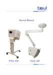
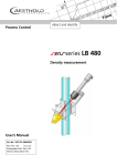
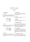
Instrument Manual
Twinkle™ LB 970T Fluorometer
Valid for instruments with software version 2.xx
BERTHOLD TECHNOLOGIES GmbH & Co.KG
Calmbacher Str.22
D-75323 Bad Wildbad, Germany
www.BertholdTech.com
2
Contents
1. Safety Information and Warnings
3
Safety Instructions for Service
Special Spare Parts
4
4
2. Functional Description
5
Fluorescence (Top Counting)
Fluorescence (Bottom Counting)
5
7
3. Installation Instructions
10
4. Instrument Installation
11
Environment
Electric Power
Connection to other units
13
13
14
5. Information about User Instructions
15
Instrument- and User Manual
On-line Help
Routine maintenance
15
15
15
6. Software Installation
15
Minimum System Requirements
Printer Installation
Installation of the Workstation software on a portable computer
Setup
7. Routine Maintenance
15
15
15
16
19
Cleaning the instrument
Changing the CW- Lamp
Compacting the database
19
19
19
8. Specifications
20
3
1. Safety Information, Warnings and Special Spare
Parts
Caution! - This symbol alerts you to important operating
considerations or a potential operating condition that could damage
equipment. Refer to the User`s Manual or Instrument`s Manual for
precautionary instructions.
General:
•
This equipment must be installed and used in accordance with the manufacturer’s
recommendations. Installation must be performed by properly trained and authorised
personnel.
•
This fluorometer is equipped with a three-wire grounded plug, a plug with a third
(grounding) pin
•
This a safety feature. If your outlet does not accomodate the three wire-plug, have an
electrician install the correct outlet, or use an adapter to ground the appliance safely. Do not
defeat the safety purpose of the grounded plug.
•
These instructions contain important operating and safety information. The user must
carefully read and understand these instructions before using the instrument.
•
Failure to follow these instructions may invalidate your warranty and/or the safe functioning
of your equipment.
•
The instrument has been designed to optimise function, reliability, safety and ease of use.
It is the user’s responsibility to install the instrument in conformance with the local electrical
codes.
•
To disconnect the instrument from power the appliance coupler must be removed from the
mains.
•
Put the instrument in such a position that it is easy to switch on / off.
•
Remove the transport protection before switching on the instrument.
4
•
Don’t block the ventilator while the instrument is running.
•
The LB970T may be transported only in its proper transportation package.
•
For cleaning of the instrument read point 7 ( Routine Maintenance ) in this manual.
•
Additionally read the notes in the User Manual on page 20, 28 and 56.
•
Since chemical substances are being used when operating the instrument, the manufacturer’s
warning and safety precautions ( R and S sets ) have to be observed.
To avoid personal injury :
•
The interior of the instrument can reach temperatures that can cause burns. Avoid contact
with the heating plates. Some parts of the instrument can remain hot without visual
indication for some time after the power is turned off.
•
The metal part over the lamp can be hot. Don’t start the instrument without the plastic
cover over the lamp !
•
Don’t use a flammable liquid inside the instrument. A fire hazard may result.
•
Don’t open the flap while the instrument is running.
Safety instruction for service
•
Disconnect the instrument from the main power prior to maintenance and servicing.
•
When the top part of the housing is removed, no safety measures are in effect. Be careful if
the instrument is running.
•
When the top part of the housing is removed, take care with any moving parts.
•
High voltage is generated in the multiplier unit. Don’t touch the unit while the instrument is
running.
•
Proper operation is ensured only when using original spare parts.
Special Spare Parts
The following spare parts are safety parts. Use always the original part from the manufacturer
or direct agent.
Fuse :
2.00A/T 5x20 UL 1986 / CSA C22.2
Id. No.: 09892
Power Supply :
JWS-150-24/A, 100-240VAC,24V/6.5A ( Lambda ) Id. No.: 34846
Power Entry Modul w. Switch :
KD14.1101.151( Schurter )
Id. No.: 34036
5
Heating Plate : 24V/40W
Halogen Photo Optic Lamp :
( Horn )
12V/75W Typ 64613 ( Tungsten )
6
Id. No.: 34846
Id. No.: 34051
2. Functional description
Fluorescence (Top Counting)
Inside the fluorometer there is a tungsten-halogen continuous wave lamp (75 W). This is used as
the light source for fluorescence measurements. The lamp unit is thermally isolated from the
measuring head by using a light-guide to channel the light to the sample. The actual wavelength
used is selected by means of a slide containing up to 5 filters.
The filter to be used can be selected by means of the software. The spectral range of the
Excitation module is 340 - 700 nm. Two positions of the standard 5-position excitation filter
slide are used for filters of 355 and 485 nm, which are specially designed for fluorescence
excitation. All standard filters are high quality interference filters with a diameter of 15 mm for
Excitation filters and 25 mm for Emission filters.
There are three empty filter positions into which customized filters can be inserted. See the
figure.
7
Light of the selected wavelength having passed through the light guide is collimated through the
sample. The stabilised excitation energy is user-adjustable to help find the optimum linear range
for the samples being measured and thus keep the output signal within the linear range of the
instrument.
Fluorescence is collimated from the plate through a mirror slide, a lens system and an 4-position
emission filter slide to a low noise photomultiplier (spectral range 400 - 700 nm) equipped with
fast single photon counting electronics.
In the emission filter slide two positions are used for emission filters of conventional
fluorescence at wavelengths of 460 and 535 nm.
Note: when the properties of a label are defined, then the filters to be used for measurements
with that label are specified. When a protocol is selected for a measurement, the appropriate
filters are moved into position automatically.
Both excitation and emission light are directed and collected from the top of the well.
See the next section for information on bottom counting.
8
Fluorescence (bottom counting)
In the case of bottom counting of prompt fluororescence samples, excitation light is directed
through a light guide underneath the plate. Emission light goes back along the same light guide
to the optical block and passes through the emission filter to the PMT.
Bottom counting means that measurements can be made for samples in which cells are at the
bottom of the wells or there are lids on wells.
Switching between top and bottom counting is done by software and both methods can be used
for the same plate.
Kinetic measurements
To investigate the kinetics of a reaction, repeat measurements are necessary. The number of
repeats (up to 100) can be specified and the time between repeats, up to 600 s. These fast
kinetic measurements can only be made if "well mode" is selected. Slow kinetic measurements
can also be made using plate repeats.
Scan measurements
Measurements can be made at different points of a well for samples in which the light output is
not homogeneous, e.g. in cell culture wells. The number of spots to be measured can be defined.
Up to ten spots can be measured in both the horizontal and vertical directions (maximum of 100
points altogether). The distance between spots can be set. The distribution of the measurement
spots can be square or circular.
9
3. Installation Instructions
Unpacking
Open the box and remove the packing.
Lift the instrument up and move it to its place of operation.
Check the fluorometer for possible transport damage.
Remove the transport protection piece as follows :
Pull on the red tab sticking out from the plate loading position.
10
The plate holder will come out revealing the transport protection piece.
Undo the two black screws holding the transport protection piece in place.
11
Remove the transport protection piece.
Remove the protection piece from the filter 1 opening. The instrument is now ready to be used.
12
4. Instrument Installation
Environment
Although normal clean laboratory conditions are usually satisfactory as an operational
environment it is useful to take the following points into consideration.
The temperature should be in a range of 25°C to 35°C, the relative humidity should not be
excessive and direct sunlight should not be able to reach the instrument.
Electric Power
Three electrical outlets each with a protective earth should be available, with., if possible, a
separate power line for the instrument itself having an isolation switch and a fuse box.
If excessive fluctuations in the mains voltage are anticipated, a main stabilizer may be necessary.
The main switch, appliance coupler and the main fuse is on the backside of the instrument.
Important : Please read the Safety Information and Warnings before you start the instrument!
Put the instrument in such a position that you will always have a good access to
the main switch and the appliance coupler.
Connection to other units
13
This fluorometer is a compact bench top unit designed for measuring prompt fluorescence by
top or bottom counting.
The software is a 32-bit application running under Windows 95, Windows 98/ Windows NT 4.0
or Windows 2000 on a PC connected to the instrument. Results are saved in a file format for
further connection to a laboratory information system. Plates are loaded manually.
Read under point 7 ( Routine Maintenance ) Compacting the database.
The figure below shows the fluorometer with a PC and a printer.
Connection
Connect the fluorometer to the serial port of the PC using the zero modem cable provided. Use
the power cable to connect the fluorometer to the mains. Switch on the PC and the fluorometer.
5. Information about User Instructions
14
Instrument- and User Manual
There are two manuals that come with the fluorometer. This Instrument Manual is for the
hardware installations and the User Manual for more detailed information necessary for
operating the fluorometer.
The Instrument Manual is normally not needed by the normal user, only by the engineer who
installs the fluorometer. However you might need it if you have to reinstall the system in another
location in the future.
On-line Help
This is supplied with the software and can be accessed by clicking Help in any window. This
“Help” gives detailed information about all features of the operation which concern the normal
user ( service information is not provided ). There is a table of contents giving an overview of
the Help, including a “How to” section, a topic index in alphabetical order, as well as a search
facility enabling any word in the help to be located. Topics are connected where relevant by
hypertext links so that you can easily find all information on a particular subject.
Routine maintenance
This is maintenance intended to be performed by the user and is described in a separate chapter
of this instrument manual. Any other maintenance than what is described there should be
performed by a qualified service person.
6. Software Installation
Minimum System Requirements
•
•
•
•
•
•
Windows 95/Windows 98/Windows NT 4.0/Windows 2000
Intel Pentium Processor
16 MB RAM (or more)
30 MB free hard disk space (or more)
CD-ROM Drive
Super VGA Drive (minimum setting is 800 by 600 pixels)
Printer Installation
Install the printer according to the instructions accompanying the printer.
15
Installation of the Workstation software on a portable computer
General
For installing the Workstation on a portable computer, connect the instrument to the free COM
port of your computer using the standard zero modem cable.
Windows NT
When installing and running the software under Windows NT/Windows 2000, the user MUST
belong to the local Administrators group. This because the security system of Windows NT
otherwise prevents the correct installation or operation of the software.
To add a user to the local Administrators group, do the following:
Note: This must be done by a user already belonging to the local Administrators group!
1. Start the User Manager program found under Administrative Tools.
2. Double-click on the username to add to the local Adminstrators group.
3. Click the Groups button.
4. Add the 'Administrators' group to the 'Member of:' listing.
5. Click OK.
6. Click OK in the User Properties window.
7. Exit the User Manager program.
8. Proceed as in Windows 95
Windows 95
Workstation Installation to a PC connected to the Net
If the installation is made with a certain user logged into the PC, a problem occurs when another
user tries to run the workstation. This is because during the installation some of the registry files
written to the hard disk will be accessible only for the one that was logged in during the
installation. To overcome this problem there are three different possibilities:
Install the workstation with the PC disconnected from the net
This is not the best possible way to do it since, depending on how the net is constructed, there
might still be problems with the registry files for the different users. Also the icons for starting
the workstation might be missing.
Make a separate installation for each user
Install the workstation for each user separately logged into the PC. All the necessary files and
icons will be accessible for each one. If there are many users this is time consuming.
Make a separate user name for the fluorometer users
The local net support person creates a single user name and password specially for the
fluorometer users. The installation is then done when logged in as this user.
16
Setup
Exit all Windows programs and insert the CD-ROM into the PC; the setup will start
automatically.
Note: If the setup does not start automatically, it is probably because the Auto insert notification
for the CD-ROM drive is not activated.
Run the setup.exe on the CD or activate the auto insert notification in the following way:
My computer->Control panel->System-> Device Manager->Double Click CD-ROM->Double
Click CD-ROM Drive->Settings-> Select Auto insert notification->OK->OK-> Yes for
rebooting the PC for the change to take effect.
The following pop-up menus will appear when the setup is started. Read the menus carefully
and follow the instructions (for first time installations the default values should be used).
Click on Next.
17
For first time installation click on Next.
(Note: When updating the software, acitvate the database for update via custom
settings)
Click Next (with no instrument, the workstation can be run in demo mode and the software
itself simulates the instrument).
18
If all settings are OK, installation is finished.
19
7. Routine Maintenance
Cleaning the instrument
The plate carrier surface should be kept clean to avoid dust and dirt entering the optics at the
measuring position. The plate carrier should be cleaned at least once a week using a soft cloth
or tissue paper soaked in a mild detergent solution or alcohol.
Changing the CW- Lamp
If the CW- Lamp needs replacing, switch off the power and pull off the cover on the right side
of the fluorometer to get access to the lamp. Unscrew the panel holding the lamp and withdraw
it through the hole in the body of the fluorometer.
Attention :
The metal panel over the lamp and the lamp itself can be hot !
Make sure the lamp is switched off and give the lamp a chance to cool before
removing it.
Do not touch the lamp, since you might damage it !
Remove the lamp from its mounting and insert a new one. Put the lamp and its mounting back
into the instrument and screw it back in place. Replace the cover, then switch on the power.
Compacting the database
You should run the Database Maintenance program on a regular basis ( weekly or monthly
depending how much you work with the fluorometer). This program will compact your
database and will in some situations increase the software performance. If you ignore that, the
access time will increase.
You can find the program by clicking on the icon in your Window Start menu. It is called
“Database Maintenance”.
20
8. Specifications
Power requirements
Power consumption:
Nominal voltage:
Nominal frequency:
Input voltage range:
180 VA
100-240 V, multirange.
50/60 Hz
85 - 264 V, 47/63 Hz
Safety standards
1. EN61010-1:1993 or IEC 1010-1:1990 + A1, modified
(Safety requirements for equipment for measurement, control and laboratory use).
2. EMC- Directive (immunity and emission )
EN 61326-1:1997/A1:19998
EN61000-3-2:1995/A1:1998
EN61000-3-3:1995
Environmental conditions
Temperature 15 - 35°C
Relative humidity 10 - 85 %.
Excitation
Tungsten-halogen lamp, 75W, lifetime typically > 300h, Spectral range 340 - 700 nm.
Filter slides
1. Excitation filter slide with 5 filter positions. Comes with high quality interference filters for
excitation, centre wavelength (bandwidth) 355 (30) nm and 485 (15) nm.
2. Emission filter slide provided with 4 filter positions with the following filters:
centre wavelength (bandwidth) 460 (30) and 535 (30) nm.
Detector
State of the art low noise/high sensitivity photon counting system, sensitive in the range of 300
to 650 nm.
Plates
1 to 864-well plates are compatible with the instrument.
The user can define non-standard plate configurations. The maximum outer dimensions are 86.0
x 128.2 x 25 mm.
Scanning
Scanning of wells (several measuring points within a well) is available.
21
Repeats
Repeated measurements or operations can be defined by plate, strip or well.
Measurement time
Detection time per well is software selectable between 0.1 - 600 seconds.
Performance
Fluorescein detection limit is < 10 fmol / well
Physical dimensions
Weight
Height
Width
Depth
17 kg
280 mm
465 mm
406 mm
Software
The instrument program is run under Windows 95, Windows 98 or Windows NT 4.0 on a
Pentium computer, minimum 16 MB memory, equipped with a CD-ROM, super VGA display
minimum resolution 800 x 600 pixels and 256 colours.
Input/Output connections
Connection to PC via serial RS 232 interface by standard 9-pin cable (zero modem cable).
The printer is connected to the parallel port of the PC.
Counting modes
Top fluorescence (340 – 650 nm)
Bottom fluorescence
Scanning
Fast or slow kinetic measurements
22