1
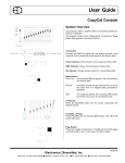
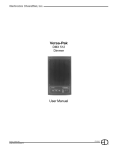
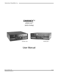
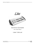
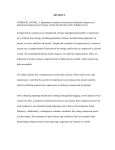
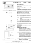
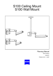
MX System Dimmer Bank
EDI
MX System Dimmer Bank
Installation Manual
June, 1998 Rev.12/99z
070-0700
©1998, Electronics Diversified, Inc.
1
Introduction
This manual is to accompany the MX series dimmer rack
by Electronics Diversified Inc. The Installation Manual is
designed to give a complete summary of necessary and
useful information. The manual is not a substitute for
qualified personnel.
If you need further information or assistance, please call
our factory technical and sales staff. Our Hillsboro factory number is noted below and at the back of this book.
The MX
This rack is designed to accommodate the MX series
dimmer modules. There are several different modules.
The difference lies primarily in the functional attributes of
the modules. Please consult the AS Built Drawings for
further information.
There are three sizes of the MX series dimmer rack the
quarter size, half and standard. These variations are
evident in vertical dimension. Operationally these are
identical.
At the top of each rack is a window giving some operational information about the rack. Part of this are two
LEDs indicating the status, that is; one which indicates
everything is okay, the other means there is some
problem within that particular rack. Just below this is the
Multi Link Intelligent Control Module.
Stacke below this unit arethe dimmer modules. There
are several different types of modules. Attention must be
paid to this configuration as different modules will have
different electrical requirements. Please consult the as
built and specifications documents to determine the type
and configuration of modules. Behind and to either side
of the modules are the electrical connections, the busses.
These are the areas with which this manual is primarily
concerned.
MX
MX 1
UFD 2
MX 1
UFD 2
MX 1
D2 2
MX 1
D2 2
EDI 24 hour Service / Support Network.
For technical questions or operational assistance please call
Customer Service at:
1-800-547-2690
This User's Manual is supplied with your MX Dimmer Bank. Copies
of this manual may be obtained from Electronics Diversified, Inc. for
a nominal charge.
Copyright 1998, by Electronics Diversified, Inc. All rights reserved.
No part of this Manual may be reproduced by any means, graphic,
electronic, or mechanical, including photocopying, recording, taping,
or information storage and retrieval systems, without the express
written permission of Electronics Diversified.
Revised 12/99
Table of Contents
Introduction . . . . . . . . . . . . . . . . . . . . . . . . . . . . . . . . 2
Illustration . . . . . . . . . . . . . . . . . . . . . . . . . . . . . . . . . 3
Installation, Leveling / Securing . . . . . . . . . . . . . . . . . . 4
Multiple Rack Bussing, wiring Access . . . . . . . . . . . . 5
Feeder Wiring . . . . . . . . . . . . . . . . . . . . . . . . . . . . . .6
Load, Neutral, Control Wiring. . . . . . . . . . . . . . . . . . . . 7
Control Module,Dimmer/Rack . . . . . . . . . . . . . . . . . . 8
Maintenance, Dimmer Removal. . . . . . . . . . . . . . . . . 9
Troubleshooting. . . . . . . . . . . . . . . . . . . . . . . . . . . . . . 9
Parts, Service . . . . . . . . . . . . . . . . . . . . . . . . . . . . . . . 10
MX System Dimmer Bank
MX Dimmer Bank Isometric Diagram
LOCATION OF FANS
KEEP CLEAR
POSSIBLE FEEDER
CABLE LOCATIONS
STATUS INDICATORS
(BEACON)
DOOR HINGE
TEST DMX2 INPUT
(CONTROL DESK)
MX 1
D2 2
MX 1
D2 2
HAND HELD
PROGRAMMER
CONNECTION
CONTROL MODULE
DIMMER MODULE
MODULAR SHELVES
CONTROL
INTERFACE
BOARD
AIR FILTERS
NEUTRAL BUSS
BACK MAINS BUSS
GROUND BUSS
CONVENIENCE OUTLETS
and
CIRCUIT BREAKER
MAINS BUSS
DOOR HINGE
SIDE PANEL
NOTE: Drawing not to scale
WELDED STEEL FRAME
Fig.1
3
WARNING:
Before working in, on, or about the MX rack, TURN
OFF, LOCK AND TAG all disconnect devices that are
supplying, or will supply power to the dimming system.
Prior to Installation
Please refer to the EDI equipment As Built drawings
specific to your project.
Also refer to the Project drawings specific to your
project.
Any question regarding the installation of this
equipment may be referred to Electronics Diversified
Inc. at:
1-800-547-2690
Note: The National Electrical Code requires 36” of
clearance in front of the rack.
Installing racks on a pedestal may cause the
circuit breakers to exceed the maximum
allowable height.
This equipment must be installed in accordance
with the National Electrical Code, State and
Local codes.
All openings, such as those for the input power
cabling, must be sealed to assure proper air flow in
through the electrostatic air filters.
Please see the maintenence section for infor mation
about cleaning and replacement of air filters.
Leveling The Rack
For proper operation the rack must be level, plumb
and square.
Use of shims is recomended on uneven surfaces.
Note: If the rack is not square, it may prevent
the installation of dimmer modules.
Securing the Rack(s)
Racks must be securely anchored to the floor. If
necessary, secure also to the wall.
Anchor holes are provided in the base of the unit.
Multiple units must be bolted together. Four bolts
are used to tie racks together.
When installing multiple rack systems, tight
coupling and sealing are required to eliminate
airleaks for proper ventilation.
Note: Local earthquake protection codes may
require additional strapping. Please consult
local requirements.
WARNING:
Maximum ambient operation and storage environment for this equipment is 104°F (40°C), with 90%
humidity, non-condensing.
UseExtreme Caution with liquids, food , fire or
flame around any powered equipment.
During severe electrical storms, equipment should
be disconnected.
Failure to adhere to these requirements may result
in malfunction or serious damage.
Installation
The location for the rack must allow adequate
clearance for proper ventilation.
The recommended clearance is 12" from the top of
the rack to any overhead ceiling.
The suggested minimum overhead clearance is 8".
When energized, the equipment is rated to produce
100 BTU per kilowatt of connected load.
Fig.2
Anchor Holes
Note: While auxillary racks have a different sized
footprint, anchor hole location is the same.
For half-size aux. racks, please consult your As Built
Drawings.
MX System Dimmer Bank
Multiple Rack Bussing
If your rack system is comprised of more than one
unit, the racks must be bolted together and bussed
together.
Install the buss links as follows:
Bonding Multiple Racks
Between the ground busses of multiple racks, attach
the supplied Green-marked ground wire.
1. To connect Inter-Rack busses for Phases A, B, C, and
the Neutral, the Rack Chassis must be bolted together.
2. Before the busses may be installed, the four bolts per
leg must be removed.
Retain the washers, lock washers and nuts for later use.
The RED spacer washers are for shipping only and may
be discarded.
3. Install the buss links using the longer bolts provided and
the previously removed hardware.
Note:
Do Not Tighten bolts until all sections are in place.
Side Panels
Multiple racks may not ship with side panels.
If present (in the case of a system expansion)the side
panels may be removed as needed.
Main Feeders
(top access)
Neutral
Fused link
Main buss to
back buss.
Buss Links
Fig.3
Ground buss
Ground bond wire
location
Wiring Access
Access is available through top, bottom, back and both sides of the rack as indicated in Fig. 1.
Recommended access is through either top or bottom.
Access through the sides may be accomplished by removing the panels and cutting through the areas as
outlined in FIG. 1, page 3 of this manual.
Access through the back is acquired in the same way, by cutting through the panel. We recommend you make
a template outlining the open areas through the back before cutting the panel.
5
WARNING:
This equipment is designed for copper wire only.
Do not use aluminum or copper-clad aluminum feeders.
Top access
main feed to:
Mains buss at left
and back buss.
Feeder Wiring
Access is designed to be from either top or bottom.
The main feeder lugs are located on the left side, or In
the case of multiple units, at the back of the unit.
Feeds to multiple racks should be installed to the buss
bars at the back of the rack. See Fig. 3.
Note: Additional bars are provided to link the main
bars at the side to these back busses.
These links may include fuse mountings.
MX 1
D2 2
Connecting Feeders
Each buss bar has two sets of holes for mounting
feeders.
These holes are designed for either clamp or wire
pressure terminal lugs of up to 700 (2X350) MCM.
The Neutral buss is sized for up to 2X500MCM lugs.
MX 1
D2 2
Control
Interface
Board
An optional 700 MCM (2 X 350) lug kit is available.
Contact EDI for more information.
Double check feeders for:
Proper torque
Correct phasing
Short circuits
Use torque supplied by the lug manufacturer for the
correct pressure.
Internal
Feeder
run with
Main
Circuit
Breaker
MX 1
D2 2
WARNING:
Installing feeders with an improper torque or the
wrong lugs may cause severe damage to the
equipment.
Double check feeders for proper torque, correct
phasing, and shorts.
Fig.4
MX System Dimmer Bank
Control Wiring
Control connections are made to the Control Interface
Board. (see Fig.1, pg.3).
All control Connections are Class II.
Please refer to the As Built Drawings specific to your
installation.
WARNING:
Feeders must clear the Dimmer Modules
as far as is possible within the confines of the rack.
Failure to provide sufficient clearance may result in
equipment malfunction and failure.
WARNING:
Load Wiring
The load connectors are all located on the right side
of the rack.
The load terminals are supplied with pressure wiring
connectors.
The lugs are designed for wire sizes of :
#6 to #14 AWG.
Note: The numbering within the rack on the output
terminal block corresponds to the respective dimmer,
the controlled load and to the control address.
MX 1
D2 2
MX 1
D2 2
Failure to provide proper Neutral circuiting may result
in Equipment Malfunction and Failure.
Clearances and Airflow
One of the most common sources of equipment
malfunction is overheating. The most common cause
of this is the improper installation of the load wiring. It
is critical that the load wiring be dressed away from
the cooling vents and fans. Each Dimmer Module is
designed to cool by means of airflow through the unit
from front to back. If the airflow is impeded, the
equipment will overheat. If the equipment overheats
it will fail.
Note: Air flow is affected by the absence of dimmer
modules. For proper cooling it is important every slot
be filled.
Note: Supplied with your rack are module blanks to
be inserted if you must remove a module, or if the rack
carries less than a full complement of modules.
Standard Electrical Characteristics
Input Power: 120/208 VAC, 3 phase, 4 wire plus
ground, 50/60Hz.
Over current: Up to 10,000 AIC standard
Interaction: None between dimmers.
Control Response: 25 milliseconds or better.
U.L. and c-U.L. listed.
MX 24
showing
load terminals
note doubles
Fig.5
Standard Mechanical Characteristics
Enclosure: Tubular steel frame, code-gauge panels
finished in scuff / impact resistant paint.
Circuit Cards: U.L. recognized.
FR-4 mil-grade material
Neutral Wiring
Each of the load circuits should have it's own Neutral.
If your installation has common neutrals pay close
attention to individual phasing per dimmer module.
The terminals are designed for wire sizes of:
#6 to #14 AWG.
Ground Wiring
Proper bonding of each load circuit is required.
The lugs are designed for wire sizes:
#6 to #14 AWG.
WARNING:
This equipment is designed for copper wire only.
Do not use aluminum or copper-clad aluminum feeders.
7
Then swing
bottom in
and let down
ce
rvi
Se
ult
Fa
B
Ø
Ø
C
2
X
DM
DM
X
1
Lift top
in first
The control module is the user interface with the electronic
brain and monitoring features of the MX series dimmer
rack. The illustration shows the location of the DMX input
connection, ( a control cable from a lighting control board
may be plugged here ). Also, to the right is the connection
for the hand-held programmer. Between these are LED
indicators of internal rack functions.
These function indicators are limited to displaying the most
basic presence or absence of the electrical or electronic
signal named on the face of the rack immediately below
each LED.
The only LED which when lighted is an indication of a
problem with the rack, or, more specifically with the
dimmer(s) in the rack, is labeled Fault. All other LEDs are
lighted when the function named is activated under normal
operation.
Also in the area of the LEDs is a service switch. This switch
is recessed and requires the aid of a small pointed tool to
acitvate. This switch allows for all the dimmers to be turned
to full-up. The switch essentially bypasses all other control
signals to the control module.
A
The door is easily removed and re-hung. It may be useful
to remove the door for maintenance or service.
A key is required to operate the cam-style locks.
To remove the door, lift the entire door up so the lower hinge
pin is disengaged.
Angle the door out at the bottom and allow it to drop down
out of the top hinge pin bracket.
To replace the door, follow the reverse of the above
procedure.
Notice the top hinge pin is longer than the bottom, the
sequence noted above is the only easy way to hang or
remove the door.
Note: The door latches operate only with a key supplied
by EDI. If You need replacement keys, please
contact our Customer Service Dept.
Control Module
Ø
Removing / hanging the Door
DMX input
Programmer port
Dimmer Module
The standard dimmer modules provide one LED indicator
per dimmer circuit which gives a visual indication of the
dimmer activity. Also provided is another LED indicator
which warns of a fault in that module.
Operational Notes:
The modules are easily installed and removed without
tools. Since it is possible you have different types or rated
modules, we suggest the rack be closed and locked at all
times.
It is likely the modules are installed in a specific order to
correspond to the wiring of the rack. Keeping the door
closed and locked may prevent the modules being moved
without reference to this order.
The cooling efficiency of the rack is seriously compromised
by the door being left open, or by unfilled slots. If this results
in the dimmer(s) overheating, the affected dimmer(s) will
shut down and not operate until the temperature has
dropped to the operational temperature range.
The following sections note the procedures for manipulating the digital dimmer parameters of the MX dimmer rack.
WARNING:
Maximum ambient operation and storage environment for this equipment is 104°F (40°C), with 90%
humidity, non-condensing.
Extreme caution is advised when liquids, food and
cigarettes are near any equipment.
During severe electrical storms, equipment should
be disconnected.
Failure to adhere to these requirements may result in malfunction or serious damage.
MX System Dimmer Bank
Dimmer and Rack Maintenance
Dimmer Removal / Installation
The MX system, like all electrical / electronic equipment
is affected by the presence of dirt and dust. We recommend the rack be opened, the modules removed and all
items cleaned to remove this dust.
Pleases follow this procedure:
•Shutdown and Disconnect Power.
•Remove the door.
•Remove each dimmer module and individually
clean either by vacuum or low pressure
compressed air.
•Clean the other interior areas of the rack in the
same manner as the individual modules.
•Inspect the internal connections of the main
feeders and of the branches to the module
plugs.
•Inspect the connector s.
•After cleaning and inspection, replace the
modules and the door.
Note: Annual cleaning is recommended, more frequently if the environment is particularly dirty.
To remove a dimmer from an MX rack please follow this
procedure:
•Be certain of the position of the Dimmer Module to be
removed. Locate this Module by using the Circuit numbering
label located to the left of the dimmers (Ck #_ ).
•Locate the Circuit Breakers - one (1) or two(2) Switches
to the left on the face of the Module to be removed.
•Move the switch toggles to the OFF postion.
•Firmly grasp the top lip of the Module and pull the
Module directly out of the module bay.
To replace a dimmer module:
•Locate the correct circuit numbers, note there are a
pair of circuits per each dimmer module.
•After carefully lining up the sides of the modules with
the appropriate shelf slots, slide the module in very firmly to
assure solid connections are made.
DO NOT SLAM THE MODULES INTO THE RACK
To help prevent the build up of dirt, the Electrostatic Air
Filters may be cleaned or replaced frequently.
To clean the Air filters:
•Remove air filters from door.
• Wash with a light to medium pressure water
spray. Use cold to lukewarm water.
• Allow to dry and replace.
Note: The filter(s) must be replaced with the correct side
facing the interior of the cabinet.
MX 1
D2 2
Troubleshooting Guide
Symptom
Possible Cause
Remedy
Nothing works, green indicators
1, 2, and 3 are dark.
Blown fuse in rack
Input power source is off.
Check input power source.
A dimmer circuitl is always OFF.
The dimmer module is not plugged in.
Defective solid-state relay.
Circuit Breaker is off.
Make sure dimmer is firmly plugged in all the way.
Check control wiring connector to solid state relays.
Replace the solid-state relay.
Turn on circuit breaker.
All of the lamps "ghost" (glow).
Dimmer preheat set too high.
Control out of calibration.
Reduce preheat level.
Contact the factory.
The dmx signal indicator flashes,
lamps flicker, or dimmers refuse to
respond to dmx signal.
Bad DMX source.
Check source.
Bad DMX cable.
Check the dimmer pack with a known good cable.
The cooling vents are blocked.
The dimmer module is full of dust.
air or a vacuum cleaner.
The dimmer is in a very warm location.
Clear any obstructions to the cooling vents.
Carefully remove dust and dirt with compressed
The dimmer pack overheats.
9
Relocate the dimmer to a cooler location.
Replacement Parts
Replacement parts are available from Electronics Diversified, Inc.
To obtain replacement parts, call (800) 547-2690 and
ask for Customer Service.
Since these systems are customized for individual
applications, it is important that you have the following information available when you call.
The equipment type or number
Serial number
Original EDI system drawing number
(As-Built Drawing Number)
Please SPECIFY LINE VOLTAGE.
When calling, the customer service representative
will help to determine the proper part you need, and
any additional parts, if necessary, depending upon
your requirement.
Service
EDI 24 hour Service / Support Network.
For technical questions about this product or
operational assistance contact Customer Service at: . . . . . . . . . . . . . . . . . .1-800-547-2690 or 1-503-645-5533
You may communicate by FAX: . . . . . . . . . . . . . . . . . . . . . . . . . . . . . . . . . . . . . . . . . . . . . . . . . 1-503-629-9877
Internet: . . . . . . . . . . . . . . . . . . . . . . . . . . . . . . . . . . . . . . . . . . . . . . . . . . . . . . . . . . . . . . . . . . . . . . . . . . . . . www.EDIonline.com
Internet E-Mail: . . . . . . . . . . . . . . .. . . . . . . . . . . . . . . . . . . . . . . . . . . . . . . . . . . . . . . . . . . . . . . . . [email protected]
If your Mark X Dimmer Bank needs repair, call 503-645-5533 for a Return Materials Authorization Number.
At that time you will be given a shipping address .
This is a product of:
1675 N.W. Cornelius Pass Road, Hillsboro, Oregon 97124 USA