1
Chapter 2. MOUNTING AND WIRING
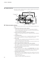
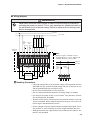
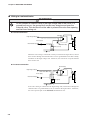
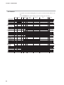
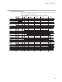
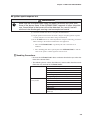
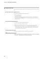
■ Wiring diagram
WARNING
Never short-circuit the start contact in order to start and stop this device by
switching the power on and off. This is very important for reliable activation of
the self-check circuit at device startup. Failure to observe this warning could
lead to an explosion.
L(R) phase
Power supply
N(S) phase
Interrupted pilot valve
Interlock
input
Intermittent pilot valve
Main valve
Ignition transformer
Start
contact
input
Flame monitor
output
12 24
11 23
10 22
21
9
20
8
19
7
18
6
17
5
16
4
15
3
14
2
1
13
Subbase for
AUR450C
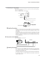
Note
Wiring for input to terminals 15 and 18
through L(R) phase contacts, without using
terminals 16 and 17, is also possible.
L(R) phase
N(S) phase
F
G
Yellow
Start
contact
input
Shutter
Unused
Interlock
input
White
18
External reset
input
17
White
16
Blue
15
Alarm output
AUD300C/500C
Advanced UV sensor
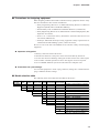
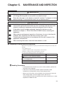
Handling Precautions
• If the high voltage side (H) of the power supply is distinguished from the
grounded side (G), connect the high voltage side (H) to terminal 13 (L1)
and the grounded side (G) to terminal 14 (N).
• Do not use unused terminals as relay terminals.
• Use an overload prevention device for the power supply as needed.
• For wiring to the power source, use a 0.75mm2 wire (30 cores, 0.18mm
dia.) in keeping with JIS C3306.
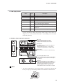
• Terminal screws for the external reset input (terminal numbers 9 and 10)
are not assembled. When using the external reset input, wire to the subbase using the included terminal screws.
• For the external reset input signal and flame voltage output signal, use IV
wire 0.75mm2 in cross-sectional area. Wire length should be 10m max.
• Although terminals with a ground mark are provided on the subbase, this
device is not grounded.
2-5