1
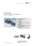
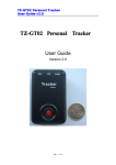
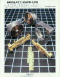
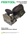
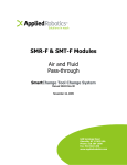
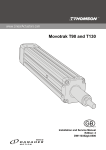
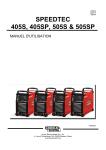
MP 45E User Manual M-605 Linear Positioning Stages Release: 1.1.0 Date: 2005-01-05 This document describes the following product(s): M-605.1DD Translation Stage, 25 mm, 0.1µm Linear Scale, ActiveDrive™ DC Motor M-605.2DD Translation Stage, 50 mm, 0.1µm Linear Scale, ActiveDrive™ DC Motor © Physik Instrumente (PI) GmbH & Co. KG Auf der Römerstr. 1 ⋅ 76228 Karlsruhe, Germany Tel. +49-721-4846-0 ⋅ Fax: +49-721-4846-299 [email protected] ⋅ www.pi.ws Declaration of Conformity according to ISO / IEC Guide 22 and EN 45014 Manufacturer: Manufacturer´s Address: Physik Instrumente (PI) GmbH & Co. KG Auf der Römerstrasse 1 D-76228 Karlsruhe, Germany The manufacturer hereby declares that the product Product Name: Linear Positioning Stage Model Numbers: M-605 Product Options: all conforms to the following EMC Standards and normative documents: Electromagnetic Emission: EN 61000-6-3, EN 55011 Electromagnetic Immunity: EN 61000-6-1 Safety (Low Voltage Directive) : EN 61010-1 Safety of Machinery: EN 12100 August 24, 2004 Karlsruhe, Germany Dr. Karl Spanner President The following designations are protected company names or registered trademarks of third parties: Windows, LabView Physik Instrumente (PI) GmbH & Co. KG is the owner of the following company names and trademarks: ActiveDrive™ Copyright 1999–2005 by Physik Instrumente (PI) GmbH & Co. KG, Karlsruhe, Germany. The text, photographs and drawings in this manual enjoy copyright protection. With regard thereto, Physik Instrumente (PI) GmbH & Co. KG reserves all rights. Use of said text, photographs and drawings is permitted only in part and only upon citation of the source Document Number MP 45E, Release 1.1.0 M-605UserMP45E110.doc This manual has been provided for information only and product specifications are subject to change without notice. About this Document Users of this Manual This manual is designed to help the reader to install and operate the M-605 Linear Positioning Stages. It assumes that the reader has a fundamental understanding of basic servo systems, as well as motion control concepts and applicable safety procedures. The manual describes the physical specifications and dimensions of the M-605 Linear Positioning Stages as well as the procedures which are required to put the associated motion system into operation. This document is available as PDF file. Updated releases are available via FTP or email: contact your Physik Instrumente sales engineer or write [email protected] Conventions The notes and symbols used in this manual have the following meanings: WARNING Calls attention to a procedure, practice or condition which, if not correctly performed or adhered to, could result in injury or death. CAUTION Calls attention to a procedure, practice, or condition which, if not correctly performed or adhered to, could result in damage to equipment. NOTE Provides additional information or application hints. Related Documents The motion controller and the software tools, which might be delivered with M-605 Linear Positioning Stages, are described in their own manuals. All documents are available as PDF files on the Motion CD or special product CD. Updated releases are available via FTP or email: contact your Physik Instrumente sales engineer or write [email protected]. ! Contents 1 M-605 Linear Stages 1.1 1.2 1.3 2 3 8 Motor Controller Setup ...............................................................8 4.1.1 4.1.2 4.1.3 4.2 6 Linear Scale Position Encoder ...................................................6 PWM Amplifiers..........................................................................6 Travel Limit Sensors...................................................................6 Position Reference Signal Sensors............................................7 Operating M-605 Stages 4.1 4 Motor Controllers........................................................................5 System Description 3.1 3.2 3.3 3.4 4 Model Survey .............................................................................3 Safety Precautions .....................................................................3 Shipment Contents.....................................................................3 Technical Data 2.1 2 Using C-842 Motor Controllers with M-605 Stages ................... 8 Using C-844 Motor Controllers with M-605 Stages ................... 9 Using Mercury Motor Controllers with M-605 stages ............... 10 Mechanical Handling ................................................................10 4.2.1 4.2.2 4.2.3 Mounting................................................................................... 10 Operating Environment ............................................................ 10 Maintenance............................................................................. 10 5 M-605 Dimensions 11 6 Pin Assignments 12 6.1 Accessories ..............................................................................13 M-605 Linear Stages 1 M-605 Linear Stages M-605 linear stages are ultra-compact, high-accuracy linear translation stages designed to meet the most demanding positioning requirements in applications where space is limited. Used in the fields of photonics packaging, semiconductor quality control, metrology test equipment, disk drive test setups and general R&D tasks, M-605 stages are designed to meet demanding positioning requirements. The stages combine a functional flat design to allow multi-axis combinations, and feature a precision-machined base from high-density, stress-relieved aluminum for exceptional stability and minimum weight. Precision-ground recirculating ballscrews, (more accurate than rolled ballscrews) and preloaded nuts provide low-friction, backlash-free positioning. Uni-directional and bi-directional repeatability are 0.1 and 0.2 µm respectively with maximum pitch and yaw errors of 50 µrad. All versions are equipped with non-contact, Hall-effect, direction-sensing origin sensors and limit switches with direction sensing at the origin. Fig. 1: M-605.1DD Translation Stage www.pi.ws M-605 MP 45E Release 1.1.0 Page 2 M-605 Linear Stages 1.1 Model Survey M-605 stages are available with travel ranges of 25 and 50 mm. All have ActiveDrive™ direct-drive DC motors. 1.2 Safety Precautions Read This Before Operating M-605 Linear Stages: ! CAUTION M-605 stages are powered by powerful electric motors and can accelerate to high speeds. Be aware that automatic limit switch halt may not be supported by, or activated at, the motor control electronics. Be aware that failure of the motor controller may drive the stage into a hard stop at high speeds. When the stage is first connected to the motor controller, be aware that the stage could start an undesired move. WARNING To avoid damage or injury, do not put anything on the bellows. Never put your finger anywhere where the moving platform or any connected object could possibly trap it. 1.3 Shipment Contents M-605 stages are delivered with www.pi.ws 4 metric screws M4x35 w. hex wrench, (purpose: mounting the stage onto a flat plane or mounting two stages as an XY combination or mounting objects onto the moving platform). Power supply, # M-500.PS Connecting cable, # C-815.38 This User Manual M-605 MP 45E Release 1.1.0 Page 3 Technical Data 2 Technical Data Models M-605.1DD M-605.2DD Units Travel range 25 50 mm Weight 1.5 1.8 kg Design resolution 0.1 µm A3 Min. incremental motion 0.1 µm A4 Unidirectional repeatability 0.1 µm Origin repeatability (reference switch) 0.2 µm Bidirectional repeatability 0.2 µm Pitch (θY) 50 µrad Yaw (θz) 50 µrad Max. velocity 50 mm/sec Max. normal load capacity 30 kg B1 20 / 20 N B2 Max. lateral force 100 N Encoder resolution 0.1 µm Max. push/pull force Ballscrew pitch 1 Motor Type Motor voltage range 17 * 0 to ±24 PWM amplifier W V LMD 18201, 24.5 kHz Encoder type linear encoder Signals A, A/, B, B/ Transmission RS-422 Power supply external line-power power supply, order # M-500.PS Power consumption Motor power plus 130 mA (supplied by external P/S) Body material Al Recommended motor controller www.pi.ws mm/rev DC motor 3557K024CS Nominal motor power* * Notes C-843, C-862, C-848 ActiveDrive™ (integrated PWM servo-amplifier), 24 V power supply included M-605 MP 45E Release 1.1.0 Page 4 Technical Data NOTES A3 Design Resolution: Theoretical minimum movement that can be made, based on characteristics of mechanical drive components selected. A4 Minimum incremental motion: The minimum motion that can be repeatably executed for a given input, sometimes called the “practical” or “operational” resolution B1 Max. Normal Load: Centered, vertical load on horizontal stage B2 Max. Push/Pull: Active and passive force limit in operating direction, at center of stage. 2.1 Motor Controllers M-605.xDD stages can be used with C-842, C-843, C-844 and C-862 (C-860) Mercury controllers. See the sections that follow for motion parameter settings. Fig. 2. C-848, C-880 and C-862 Mercury controllers; C-842 (ISA bus) and C-843 (PCI bus) controller cards www.pi.ws M-605 MP 45E Release 1.1.0 Page 5 System Description 3 System Description 3.1 Linear Scale Position Encoder M-605 stages use linear scale position encoders with 0.1 µm resolution for position detection. Maximum velocities of 50 mm/s can be achieved. The linear encoder is mounted in the center of the stage, close to the ballscrew drive to prevent possible cosine error. The linear encoder measures the actual position of the moving carriage directly, thus eliminating drivetrain errors such as nonlinearity, backlash or elastic deformations. The encoder is based on an optical grating and a noncontacting read head with integrated signal conditioner and interpolator. 3.2 PWM Amplifiers For maximum dynamic performance, the DC servo-motors are driven by high-efficiency PWM power amplifiers integrated into the stages. An external line-power power supply (order number: M-500.PS) is provided to supply the built-in amplifiers directly. This architecture allows high torque and high velocities while loading the motor controller with control signals only. The actual power is provided by the external supply. 3.3 Travel Limit Sensors M-605 stages are protected against running into the hard stop by double-level magnetic limit sensors (Hall-effect sensors with TTL drivers) at each end of travel. The inner limit sensors (N1 at the negative-travel end and P1 at the positive-travel end) work with the controller's limit sense input lines. The TTL output signal is active high. The outer limit sensors (N2 at the negative and P2 at the positive end) work locally, opening a relay that cuts the motor current. The second-level limit switches provide for fail-safe operation in case the controller fails to stop the motor when the inner limit sensor is reached. If the outer limit switch is reached, the stage can not be operated by the controller until the platform is pushed back www.pi.ws M-605 MP 45E Release 1.1.0 Page 6 System Description manually. Disconnect the motor cable or set the motor into MOTOR OFF state before pushing the platform back into the current-allowed area. Limit Switch Sensor Specifications: Type: magnetic (Hall-effect) sensors, can be used with bipolar CMOS circuits Power supply. +5...+24 V / GND, supplied by the motor controller through the motor connector Voltage output: TTL level Sink / Source current: ± 48 mA Logic (active-high): 3.4 Normal motor operation: low, Limit switch reached: high Position Reference Signal Sensors Position Reference Sensors are located approximately in the middle of the operating range and can be used to reference the absolute position of the stage within 0.5 µm accuracy. Always approach the reference sensor from the same side to reach the same position. The reference sensor in M-605 stages provides a static signal level which depends on the platform position. If the platform is on the “positive side” the reference signal is +5 V, while if the platform is on the “negative side,” the signal level is 0 V. Most PI motor controllers and Windows libraries offer the option of starting a search run for the reference point using the current reference sensor signal to determine the appropriate direction. The "AutoFindReference" function allows for starting a search run for the reference signal. Independent at which side relative to the reference position the stage is located, this function always starts the stage towards the reference position. www.pi.ws M-605 MP 45E Release 1.1.0 Page 7 Operating M-605 Stages 4 Operating M-605 Stages M-605.1DD and M-605.2DD stages have internal linear scales and PWM amplifiers. Individual setting of motion control parameters is required for smooth and optimized movement. Incorrect parameter setting may cause severe spindle vibration. If this occurs set the motor off (MF) and modify the parameter settings. 4.1 Motor Controller Setup The tables shown in this section give good conservative starting values for the proportional (P), integral (I), differential (D) parameters of the PID servo-control algorithm used by the corresponding controller, as well as the acceleration and velocity limits to use. The table entries include the command mnemonic to use in the controller command language to set the corresponding value. 4.1.1 Using C-842 Motor Controllers with M-605 Stages WinMove and WinMoveNT are the standard operating programs for C-842 motor controllers being operated from Windows platforms. WinMove allows configuration of the M-605 stages with a configuration file. WinMove software automatically handles amplifier mode setting as a function of the stage model number selected. The amplifier mode can also be set by command: PWM mode is enabled by the "SOP" command while analog mode is enabled by the "SOH" command. Sample Configuration File for Use by WinMove (version 3.00 or later) : ; File: "WINMOVE.CFG" ; WinMove Configuration File for C-842 ; -----------------------------------BOARDMODE=9 LIMITMODE=autodetect STAGE1=M-605.2DD STAGE2=M-605.2DD www.pi.ws M-605 MP 45E Release 1.1.0 Page 8 Operating M-605 Stages C-842 Parameter Settings for Parameter p- term i- term d- term i- Limit vff- term Acceleration Velocity M-605.1DD DP100 (50 to 120) DI100 (0 to 120) DD200 (0 to 250) DL2000 DF500 (0 to 700) SA500 (40 to 1000) SV150000 (1 to 250,000) Range M-605.2DD DP100 (50 to 120) DI100 (0 to 120) DD200 (0 to 250) DL2000 DF500 (0 to 700) SA500 (40 to 1000) SV150000 (1 to 250,000) 485,000 counts 4.1.2 Using C-844 Motor Controllers with M-605 Stages DCMove is the standard C-844 operating program. This program uses a configuration file to define the motion control parameters. First use the parameter menu to set these values: PWM mode is enabled by the OUTP:SIGN PWM command, while analog mode is enabled by the OUTP:SIGN DAC command. C-844 Parameter Settings for M-605 Stages p-i-d terms i- Limit vff- term Acceleration Velocity www.pi.ws M-605.1DD PID 100,100,200 p : 30 to 120 i : 0 to 120 d : 0 to 250 LIM:IERR 2000 VFF500 (0 to 700) ACC 1250000 (100,000 to 1,800,000) MVEL 180000 (1 to 250,000) M-605 MP 45E Release 1.1.0 M-605.2DD PID 100,100,200 p : 30 to 120 i : 0 to 120 d : 0 to 250 LIM:IERR 2000 VFF500 (0 to 700) ACC 1250000 (100,000 to 1,800,000) MVEL 180000 (1 to 250,000) Page 9 Operating M-605 Stages 4.1.3 Using Mercury Motor Controllers with M-605 stages The Windows operating program for the Mercury controller allows choice of M-605 stages as a start option for operation. Mercury always has the PWM mode enabled without any extra command. Mercury C-862 Parameter Settings for M-605 Stages p- term i- term d- term i- Limit Acceleration Velocity 4.2 M-605.1DD DP120 (50 to 150) DI20 (0 to 40) DD200 (0 to 350) DL2000 SA1200000 (100,000 to 1,800,000) SV150000 (1 to 250,000) M-605.2DD DP120 (50 to 150) DI20 (0 to 40) DD200 (0 to 350) DL2000 SA1200000 (100,000 to 1,800,000) SV150000 (1 to 250,000) Mechanical Handling 4.2.1 Mounting M-605 stages can be mounted in any orientation, horizontally or vertically. To achieve the specified guiding accuracy, the stages must be mounted on a flat surface to avoid torsion of the base. 4.2.2 Operating Environment M-605 stages require clean environments for operation. Although provided with a flexible bellows to protect against dust and liquids, the unit is not hermetically sealed. Make sure that metal dust and liquid spray do not enter the case. 4.2.3 Maintenance When operated in a clean environment, no maintenance is required. If the stages are operated in extremely dusty environments, we recommend cleaning and greasing the ballscrew and linear bearings from time to time. The time interval depends of the degree of contamination and can vary from 100 to 800 operating hours. Recommended lubricant for ballscrews: KLÜBER Staburags Type NBU 8EP or Beacom 325 www.pi.ws M-605 MP 45E Release 1.1.0 Page 10 M-605 Dimensions 5 M-605 Dimensions Decimal places delimited by commas in drawings Fig. 3: M-605.1DD Fig. 4: M-605.2DD www.pi.ws M-605 MP 45E Release 1.1.0 Page 11 Pin Assignments 6 Pin Assignments M-605 stages are equipped with one sub-D15(m) socket for connecting the motor controller and one 3-pin, round connector for the power supply. Connector J1 (Power Supply) Type: Reference No: 3-pin, round socket Switchcraft Tini Q-G PIN Signal 1 2 3 GND Voltage input n.c. Connector J2 (Signals, Controller connection) Type: Reference No.: Pin Signal 1 Control input for optional motor brake (0 to 24 V) n.c. n.c. PGND PWM MAGN input PWM SIGN input +5 V input NLIMIT output (Limit signal of negative side) PLIMIT output (Limit signal of positive side) Reference sensor output GND (Limit) Encoder A(+) output Encoder A(-) output Encoder B(+) output Encoder B(-) output 9 2 10 3 11 4 12 5 13 6 14 7 15 8 www.pi.ws 15-pin sub-D connector AMP #9-215594-1 M-605 MP 45E Release 1.1.0 Page 12 Pin Assignments 6.1 Accessories Fig. 5: M-605.AV1angle bracket for vertical mounting www.pi.ws M-605 MP 45E Release 1.1.0 Page 13