1
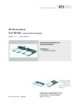
MP 40E User Manual M-227 Release: 1.12 DC-Mike Actuators Date: 2003-06-02 This document describes the following Product(s): M-227.50 DC-Mike Drive, 50 mm M-227.25 DC-Mike Drive, 25 mm M-227.10 DC-Mike Drive, 10 mm © Physik Instrumente (PI) GmbH & Co. KG Auf der Römerstr. 1 ⋅ 76228 Karlsruhe, Germany Tel. +49-721-4846-0 ⋅ Fax: +49-721-4846-299 [email protected] ⋅ www.pi.ws M-227 DC-Mike Actuators User Manual MP 40E Table of Contents : 1 Manufacturer Declarations 3 2 High-Resolution DC-Mike Actuators 4 2.1 Features..........................................................................................4 2.2 Application Examples......................................................................5 3 M-227 and PI Motor Controllers 6 3.1 Maximum Travel Speed ..................................................................6 3.2 Using C-860 Mercury Controllers....................................................6 3.3 Using C-842 and C-848 Motor Controllers......................................7 3.4 Using C-844 Motor Controllers .......................................................7 4 Quick Start 8 4.1 Mounting Recommendations ..........................................................8 4.2 Move Direction ................................................................................8 4.3 Travel Ranges.................................................................................8 5 Troubleshooting 5.1 9 Fixing a Hard-Stop-Blocked DC-Mike .............................................9 5.1.1 Electric Recovery .......................................................................9 5.1.2 Mechanical Recovery .................................................................9 5.2 Fixing a Slipping DC-Mike Coupling ...............................................9 6 Technical Data 10 6.1 M-227 Pin Assignment..................................................................12 6.2 Dimensions ...................................................................................13 6.3 Optional Tips.................................................................................13 © 2003 by Physik Instrumente (PI) GmbH & Co. KG, D-76228 Karlsruhe File: M-227_User_MP40E112.doc, 1101824 bytes Release 1.12 www.pi.ws Page 2 M-227 DC-Mike Actuators 1 User Manual MP 40E Manufacturer Declarations Warranty Physik Instrumente (PI) warrants DC-Mike-Drives to be free from defects in material and workmanship for a period of one year from the date of shipment. The warranty does not apply to defects resulting from misuse or any product modification without PI´s express written consent. This warranty does not apply to problems arising from normal wear. Safety Precautions SAFETY PRECAUTONS Following safety precautions should be observed before operating DC-Mike Drives : ¾ DC-Mikes are motorized and can generate high forces. If handled improperly, the drives may cause injuries. Be aware that failure of the motor controller may drive the DC-Mike into a hard stop generating a large force. ¾ When the DC-Mike is connected to a DC-Motor Controller (and / or amplifier) be aware that the drive could start an undesired move due to whatever reason. ¾ To avoid injury, do not put any parts in the gap between the moving DCMike and any rigid structure. ¾ Never put your finger at a place where the moving DC-Mike or any connected object could possibly trap it ! ¾ To avoid damage, do not drive the actuator into the mechanical limit. Release 1.12 www.pi.ws Page 3 M-227 DC-Mike Actuators 2 User Manual MP 40E High-Resolution DC-Mike Actuators M-227 DC-Mike Actuators are motorized linear translation drives with extra-high position resolution. 2.1 Features ¾ 10, 25 & 50 mm Travel Range ¾ 0.05 µm Minimum Incremental Motion ¾ Non-Rotating Tip ¾ Velocity to 1 mm/sec. ¾ Closed-Loop DC Motor ¾ Optional Sub-nm-Resolution Piezo Tip M-227s are ultra-high-resolution linear actuators providing linear motion up to 50 mm with sub-micron resolution in a compact package. They consist of a micrometer with non-rotating tip driven by a closed-loop DC motor/gearhead combination with motor shaft mounted high-resolution encoder (2048 counts/rev.). If you need a unit with limit switches, consider other DC-Mike versions, such as the M-230. Compared to conventional rotating-tip micrometer drives, the non-rotating tip design offers several advantages: ¾ Elimination of torque-induced positioning errors ¾ Elimination of sinusoidal-motion errors ¾ Elimination of wear at the contact point ¾ Elimination of tip-angle-dependent wobble M-227 actuators provide a cost-effective solution for industrial and OEM environments. The combination of an extremely low stiction/friction construction and high-resolution encoder allows for minimum incremental motion of 50 nanometers at speeds up to 1 mm/sec. Each actuator includes an integral 0.1 m cable with 15 pin sub-D connector and a 3 m extension cable. The connector features integrated line drivers for cable lengths up to 10 meters between actuator and controller. Release 1.12 www.pi.ws Page 4 M-227 DC-Mike Actuators User Manual MP 40E M-227.10 DC-Mike Actuator 2.2 Application Examples ¾ Metrology ¾ Photonics packaging ¾ Fiber alignment ¾ Quality control ¾ Test equipment. All models come with standard flat tips. A variety of other tips are also available, such as a piezoelectric (PZT) tip featuring 20 µm travel with sub-nanometer resolution. The PZT option is ideal for dynamic scanning and tracking. For mounting, DC-Mikes are clamped around the 19 mm diameter sleeve. (High forces around the 16 mm sleeve section will increase friction and reduce accuracy and must be avoided, as must lateral forces on the tip.) A stepper-motor-driven unit is available as the M-168 Stepper-Mike, which is described in a separate manual. For higher loads and integrated limit switches consider the M-230 and M-235 DC-Mikes. Datasheets are available, or visit www.pi.ws. Release 1.12 www.pi.ws Page 5 M-227 DC-Mike Actuators User Manual MP 40E 3 M-227 and PI Motor Controllers 3.1 Maximum Travel Speed At 12 V operating voltage the maximum speed of M-227 actuators is about 280,000 counts/s. At this speed the closed-loop velocity control does not have quite enough margin, so the specified maximum operating speed is 250,000 counts/s, equivalent to a travel velocity of 0.875 mm/s. At 15 V operating voltage a speed of 1 mm/s can be achieved. Note: If the programmed velocity is too large, accelerating and decelerating ramps will not be performed as programmed by the SA command and the physical velocity is smaller than the profile velocity. When this happens the trajectory generator may have already completed its move while the actuator is still trying to catch up. 3.2 Using C-860 Mercury Controllers C-862 Mercury II Controller Extension cables up to 3 m are available. Mercury parameter settings Parameter Value Range Sample Mercury Command P-Term i-Term D-Term i-Limit Acceleration Velocity 250.-300 0.-25 0--350 2,000 1,200,000 0--250,000 DP250 DI12 DD250 DL2000 SA1200000 SV190000 Release 1.12 www.pi.ws Page 6 M-227 DC-Mike Actuators 3.3 User Manual MP 40E Using C-842 and C-848 Motor Controllers Using C-842 DC-Motor controllers with DC-Mike Drives, WinMove operating software can be used for convenient motion control. C-842 parameter settings using WinMove software or QFL libraries 3.4 Parameter Value Range C-842 Command P-Term i-Term D-Term i-Limit Acceleration Velocity 250-300 0-25 0-350 2000 480 0-250000 DP250 DI12 DD250 DL2000 SA480 SV190000 Using C-844 Motor Controllers The C-844 controller is no longer recommended and virtually unavailable. Operating M-227 DC-Mikes with C-844 DC-Motor Controllers, DCMove software offers easy commanding of servo-control parameters and positions. Recommended parameter settings for C-844 Parameter Value Range Sample C-844 Command P-Term i-Term D-Term i-Limit Acceleration Velocity 200-350 0-25 0-350 2,000 1,200,000 0-250,000 PID 300,0,0 PID 300,0,0 (set PID 400,10,1200 if needed) PID 300,0,0 (set PID 400,10,1200 if needed) LIM 2000 ACC 800000 MVEL 190000 Note: The acceleration settings in the DCMove environment is direct given in counts/s2 Note: If the programmed velocity is too large, accelerating and decelerating ramps will not be performed as programmed by SA command. The trajectory generator has already completed the move while the stage is still trying to catch up. Release 1.12 www.pi.ws Page 7 M-227 DC-Mike Actuators User Manual MP 40E 4 Quick Start 4.1 Mounting Recommendations Whenever possible the DC-Mike drives should be mounted with two holders, at least one of them clamping at the 19 mm diameter (the silverish front part). Clamping force at the 16mm diameter shaft should be as small as possible to avoid high friction and possible damage to the screw. can also be clamped here. Clamp here, slightly, to avoid excessive friction, note this is a "weak" shaft. If you have the optional P-250 piezo tip, be sure to observe the mounting instructions that come with that product. Applying excessive force, even once (e.g. during installation) can destroy the PZT. 4.2 Move Direction Move inward by commanding negative directions Move outward by commanding positive directions Dwg.: A- MP31 4.3 Travel Ranges M-227 DC-Mikes are available with travel ranges of 10, 25 and 50 mm. Since the compact design does not allow for internal limit switches, take care while commanding positions and do not drive the actuator into the mechanical limit. Caution: To avoid damage, do not drive the actuator into the mechanical limit. All PI motor controllers support limit switches. We strongly recommend the use of external limit switches with every M-227 DC-Mike Drive application. Release 1.12 www.pi.ws Page 8 M-227 DC-Mike Actuators User Manual MP 40E 5 Troubleshooting 5.1 Fixing a Hard-Stop-Blocked DC-Mike 5.1.1 Electric Recovery If a move command does not work and the DC-Mike is still clamped in the hard stop, an external DC voltage of 15 V may help. Disconnect the DC-Mike from the controller and apply the voltage to the motor. Use a power supply with a variable output voltage and set the voltage to 15 Volts. Apply the voltage to the connector for a short moment (less than 2 sec.) Make sure that the polarity is right to retract from the hard stop. For positive move (expansion): pin 2 +15 V, pin 9 GND 5.1.2 Mechanical Recovery If the Mike is driven into one side hard stop, the spindle may become jammed and not retract without manual help. Here are some instructions for loosening the blocked mike: You need a 1.2 mm Allen wrench. 1. Remove the set screw located about in the middle of the black tube. This screw clamps the motor/gearhead assembly inside the black housing. 2. Hold the Mike with both hands and turn the black part counterclockwise (CCW) relative to the silver part until it breaks loose. Look for the small hole (dia. 2.5 mm) in the black part near the edge to the silverish part. This hole allows access to 2 set screws which clamp the bellows coupling to the spindle. Rotate until you see the first set screw through the hole and untighten it. 3. Turn the black housing until you see the second set screw and untighten it also. 4. Turn the black tube CCW until you can pull it apart from the silverish part. 5. Turn the spindle CW or CCW in order to loosen the jammed spindle. 6. Re-assemble the DC-Mike 5.2 Fixing a Slipping DC-Mike Coupling The metal bellows coupling is clamped by two small radial set screws to the spindle. In the rare case that the coupling slips, these two screws need to be retightened. To do this, the DC-Mike must be disassembled: You need a 1.2 mm Allen wrench. 1. Remove the set screw located about in the middle of the black tube fixing the motor/gear head assembly. 2. Turn the motor/gearhead assembly with the cable until one of the radial set screws clamping the coupling bellow can be seen through the hole near the transition from the black to the silverish part of the mike. 3. Untighten the set screw 4. Turn the motor/gearhead assembly until the second set screw appears beneath the hole. Untighten this set screw also. 5. Now the Motor/gear head assembly can be pulled out of the black tube. 6. Examine the connection of the coupling bellows with the gear shaft and tighten both fixing screws. 7. Reassemble the DC-Mike. Release 1.12 www.pi.ws Page 9 M-227 DC-Mike Actuators 6 User Manual MP 40E Technical Data M-227 DC-Mike Actuators are available with three travel ranges: M-227.10: 10 mm M-227.25: 25 mm M-227.50: 50 mm Other specifications are identical. M-227 Models Travel range Design resolution (1 count) Min. incremental motion Unidirectional repeatability Backlash Max. velocity Max. push/pull force* Max. lateral force Encoder resolution Drivescrew pitch Gear ratio** Nominal motor power Motor voltage range Weight Recommended motor controllers M-227.10 10 0.0035 0.05 0.1 2 1 M-227.25 25 0.0035 0.05 0.1 2 1 M-227.50 50 0.0035 0.05 0.1 2 1 Units Notes mm A3 µm A4 µm µm µm mm/s ec N N (at tip) Count s/rev. mm/re v. 40 0.1 40 0.1 40 0.1 2048 2048 2048 0.5 0.5 0.5 69.12:1 2 0 to ±12 0.16 C-842, C-843, C-848, C-862 69.12:1 2 0 to ±12 0.22 C-842, C-843, C-848, C-862 69.12:1 2 W V 0 to ±12 0.26 kg C-842, C-843, C-848, C-862 P-250 (PZT Tip Option) P-250.20 Units Notes Open-loop travel @ 0 to -1000 V 20 A7, A44 µm ±20% ***Open-loop resolution 0.2 nm C2 20 D1 Static large-signal stiffness ***** N/µm ±20% Push/pull force capacity 100 / 5 N D3 Max. operating voltage range 0 to -1000 V A7 22 F1 Electrical capacitance nF ±20% Dynamic operating current coefficient 1.4 µA/(Hz x µm) F2 (DOCC) 11 G2 Unloaded resonant frequency (f0) kHz ±20% -40 to +80 Standard operating temperature range °C ****Voltage connection VH J1 28 K Weight (without cables) g ±5% Recommended Amplifier: E-461.00 (bench-top) or E-461.OE (OEM module) or E-500 chassis + E-507 (1-channel amp.) + optional E-516 display/interface Notes M-227 *Higher forces on request 2 **Gearhead formula: 39 + 1 39 + 1 9 15 Release 1.12 www.pi.ws Page 10 M-227 DC-Mike Actuators User Manual MP 40E A3 Design Resolution The theoretical minimum movement that can be made, based on the selection of the mechanical drive components (drive screw pitch, gear ratio, angular motor resolution, etc.). Design resolution is usually better than the practical position resolution (minimum incremental motion). A4 Minimum Incremental Motion The minimum motion that can be repeatably executed for a given input, which is sometimes referred to as practical or operational resolution. Design resolution and practical resolution have to be distinguished. Design resolutions of 1 nm or better can be achieved with many motor, gearbox and leadscrew combinations. In practical applications, however, stiction/friction, windup, and elastic deformation limit operating resolution. P-250 Optional Piezoelectric Tip ***Resolution of PZT actuators is not limited by friction or stiction. Noise equivalent motion with E-507 amplifier; **** Model P-250.10 with BNC connector; ***** Dynamic small-signal stiffness ~50% higher A7 Max. Operating Voltage Translators with a maximum negative operating voltage of -1000 V should not be operated at voltages in excess of -700 V for long durations. Operation in the range of +200 to -750 V is recommended for maximum lifetime. For details see "Tutorial: Piezoelectrics in Positioning" in the PI Catalog or at www.pi.ws. A44 Open-Loop Travel @ 0 to -1000 V Typical open-loop travel at 0 to -1000 V operating voltage. C2 Open-Loop Resolution Resolution of piezo actuators is basically infinitesimal because it is not limited by stiction and friction. Instead of resolution, the noise-equivalent motion is specified. Values are typical results (RMS, 1σ), measured with E-507 amplifier module in E-500/501 chassis. D1 Static Large-Signal Stiffness Calculated based on the Young's modulus of the PZT ceramics material. Dynamic smallsignal stiffness differs significantly because of effects caused by the active nature of PZT material, compound effects, etc. For details see "Tutorial: Piezoelectrics in Positioning" in the PI Catalog or at www.pi.ws. D3 Push/Pull Force Capacity (in operating direction) Limited by the PZT ceramic material and preload. If larger forces are applied, damage to the PZT or the sensor can occur. The force limit must also be considered in dynamic applications. Example: the dynamic forces generated by sinusoidal operation at 1000 Hz, 2 mm peakpeak, 1 kg moved mass are approximately ±40 N. For details see "Tutorial: Piezoelectrics in Positioning" in the PI Catalog or at www.pi.ws. F1 Electrical Capacitance The PZT capacitance values indicated in the technical data tables are small-signal values (measured at 1 V, 1000Hz, 20°C, no load); large-signal values at room temperature are 30 to 50% higher). The capacitance of PZT ceramics changes with amplitude, temperature, and load, up to approximately 200% of the unloaded, small-signal capacitance at room temperature. For detailed information on power requirements, refer to the amplifier frequency response graphs in the "PZT Control Electronics" section of the PI Catalog or on www.pi.ws. F2 Dynamic Operating Current Coefficient (DOCC) Average electrical current (supplied by the amplifier) required to drive a piezo actuator per unit frequency and unit displacement (sine wave operation, open-loop—up to 50% more in Release 1.12 www.pi.ws Page 11 M-227 DC-Mike Actuators User Manual MP 40E closed-loop operation). For example, to find out if a selected amplifier can drive a given piezo actuator at, say, 100 Hz with 5 mm amplitude, multiply DOCC by 100 X 5 and check if the result is smaller or equal to the output current of the selected amplifier. For details see "Tutorial: Piezoelectrics in Positioning" in the PI Catalog or at www.pi.ws. G2 Unloaded Resonant Frequency (f0) First resonant frequency in operating direction (does not specify the maximum operating frequency, which is considerably lower!). For details see "Tutorial: Piezoelectrics in Positioning" in the PI Catalog or at www.pi.ws. J1 Voltage Connection VH: (Voltage High) LEMO FFA.0A.250, male.Cable: coaxial, RG 174,PVC coated, 1 m. For extension cables and adapters, see "Accessories" in the "PZT Control Electronics" section of the PI Catalog or visit www.pi.ws. K Weight of Translator without Cables The typical weight of a 1 m drive cable with LEMO connector is 19 g (VH) 6.1 M-227 Pin Assignment Sub-D 15f connector: PIN 1 2 3 4 5 6 7 8 9 10 11 12 13 14 15 Function internal use Motor (+) input internal use +5 V input Not used GND (Logic) A(-) when using RS422 transmission B(-)when using RS422 transmission Motor ( - ) input internal use internal use Not used Not used Encoder A (A(+) when using RS422 transmission) Encoder B (B(+) when using RS422 transmission ) Release 1.12 www.pi.ws Page 12 M-227 DC-Mike Actuators 6.2 User Manual MP 40E Dimensions M-227 DC-Mike 6.3 Optional Tips P-250.20 Piezo Tip option Release 1.12 M-219 Ball Tip option www.pi.ws Page 13