1
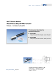
MP 44E User Manual M-505 Release: 1.1.3 Linear Positioning Stages Date: 2006-03-10 This document describes the following product(s): M-505.xxx Linear Positioning Stages © Physik Instrumente (PI) GmbH & Co. KG Auf der Römerstr. 1 ⋅ 76228 Karlsruhe, Germany Tel. +49-721-4846-0 ⋅ Fax: +49-721-4846-299 [email protected] ⋅ www.pi.ws M-505 Linear Stages Operating Manual MP 44E Table of Contents 0 Manufacturer Declarations................................................... 2 0.1 0.2 0.3 1 Warranty ........................................................................................... 2 Safety Precautions............................................................................ 2 Declaration of Conformity ................................................................. 2 General Design of M-505 Linear Stages,............................. 3 1.1 1.2 1.3 2 Model Survey .................................................................................... 4 Technical Data .................................................................................. 5 Shipment Contents ........................................................................... 6 Specifications........................................................................ 6 2.1 2.2 2.2.1 2.2.2 2.3 General Data..................................................................................... 6 Specific Data for DC Motor Versions ................................................ 6 Type ".PD": Stages with ActiveDrive™ DC Motor............................. 6 Type ".DG": Stages with Gearhead Drives ....................................... 6 Recommended Motor Controllers ..................................................... 7 3 PWM Amplifiers..................................................................... 7 4 Position Sensors................................................................... 8 4.1 4.2 4.3 5 Limit Switches ................................................................................... 8 Position Reference Signal Sensors .................................................. 9 Operating M-505 Stages................................................................... 9 Motor Controller Setup ....................................................... 10 5.1 5.2 5.3 6 Using C-842 Motor Controllers with M-505 Stages......................... 10 Using C-844 Motor Controllers with M-505 Stages......................... 11 Using Mercury Motor Controllers with M-505 stages ...................... 11 Mechanical Handling .......................................................... 12 6.1 6.2 6.3 Mounting ......................................................................................... 12 Operating Environment ................................................................... 12 Maintenance ................................................................................... 12 7 M-505 Dimensions............................................................... 13 8 Pin Assignments ................................................................. 14 8.1 8.2 9 M-505.xPD ...................................................................................... 14 M-505.xDG...................................................................................... 15 M-505 Stages with Stepper Motors.................................... 15 9.1 M-505.xS2 (using 2-phase stepper motors).................................... 15 © Copyright 2006 by Physik Instrumente (PI) GmbH & Co. KG Release: 1.1.3 File:M-505_User_MP44E113.doc, 378880 Bytes Release 1.1.3 www.pi.ws Page 1 M-505 Linear Stages Operating Manual MP 44E 0 Manufacturer Declarations 0.1 Warranty Physik Instrumente (PI) warrants M-505 stages to be free from defects in material and workmanship for a period of 1 year from the date of shipment. The warranty does not apply to defects resulting from misuse or any product modification without PI´s express written consent. This warranty does not apply to problems arising from normal wear. 0.2 Safety Precautions Read This Before Operating M-505 Linear Stages: • M-505 stages are powered by powerful electric motors and can accelerate to high speeds. Be aware that automatic limit switch halt may not be supported by, or activated at, the motor control electronics. • Be aware that failure of the motor controller may drive the stage into a hard stop at high speeds. • When the stage is first connected to the motor controller, be aware that the stage could start an undesired move. • To avoid damage or injury, do not put anything in the gap between the moving platform and the motor cabin. • Never put your finger anywhere where the moving platform or any connected object could possibly trap it. 0.3 Declaration of Conformity The manufacturer, Physik Instrumente (PI) GmbH & Co. KG, Karlsruhe, Germany, declares that the M-505 Linear Stages comply with the ISO / IEC Guideline 22 and EN 45014 European Standards. CE markings have been affixed to the device accordingly. Release 1.1.3 www.pi.ws Page 2 M-505 Linear Stages 1 Operating Manual MP 44E General Design of M-505 Linear Stages, M-505 linear stages are low-profile, high-accuracy linear translation stages for industrial use and laboratory applications. Used in the fields of semiconductor quality control, metrology test equipment, disk drive test setups and general R&D tasks, the M-505 stages are designed to meet demanding positioning requirements. The stages combine a functional flat design to allow multi-axis combinations, and feature a precision-machined base from high-density, stress-relieved aluminum for exceptional stability and minimum weight. Precision-ground recirculating ballscrews (more accurate than rolled ballscrews) and preloaded nuts provide lowfriction, backlash-free positioning. Full-travel accuracy is 1 µm and the ActiveDrive™ versions have a unidirectional repeatability or 0.25 µm. High-precision linear guiding rails with recirculating ball bearings guarantee 1 µm / 100 mm straightness and flatness. All versions are equipped with non-contact, Hall-effect, direction-sensing origin sensors and limit switches. M-505 Stages Dwg.: M505_small.TIF Release 1.1.3 www.pi.ws Page 3 M-505 Linear Stages 1.1 Operating Manual MP 44E Model Survey M-505 stages are available with travel ranges of 25, 50, 100 and 150 mm. Depending on the application, integrated drives using DC motor / gearhead combinations, ActiveDrive™ DC motor or 2-phase stepper motors are offered. M-505.1DG M-505.1PD M-505.1S2 Linear Positioning Stage, 25 mm, DC Motor/Gearhead Linear Positioning Stage, 25 mm, ActiveDrive™ DC Motor Linear Positioning Stage, 25 mm, 2-Phase Stepper Motor M-505.2DG M-505.2PD M-505.2S2 Linear Positioning Stage, 50 mm, DC Motor/Gearhead Linear Positioning Stage, 50 mm, ActiveDrive™ DC Motor Linear Positioning Stage, 50 mm, 2-Phase Stepper Motor M-505.4DG M-505.4PD M-505.4S2 Linear Positioning Stage, 100 mm, DC Motor/Gearhead Linear Positioning Stage, 100 mm, ActiveDrive™ DC Motor Linear Positioning Stage, 100 mm, 2-Phase Stepper Motor M-505.6DG M-505.6PD M-505.6S2 Linear Positioning Stage, 150 mm, DC Motor/Gearhead Linear Positioning Stage, 150 mm, ActiveDrive™ DC Motor Linear Positioning Stage, 150 mm, 2-Phase Stepper Motor Release 1.1.3 www.pi.ws Page 4 M-505 Linear Stages 1.2 Operating Manual MP 44E Technical Data M-505.1PD M-505.1DG M-505.1S2 M-505.2PD M-505.2DG M-505.2S2 M-505.4PD M-505.4DG M-505.4S2 Models M-505.6PD M-505.6DG M-505.6S2 Units Notes Travel range 25/50/100/150 25/50/100/150 25/50/100/150 mm Design resolution 0.25 0.017 0.05 µm A3 Min. incremental motion 0.25 A4 0.05 0.1 µm Unidirectional repeatability 0.25 0.1 0.1 µm Bidirectional repeatability 1 1 µm 1 Accuracy per 25 mm 1 1 1 µm Straightness 1 1 1 µm Flatness 1 1 1 µm Pitch (θy) 50 50 50 µrad Yaw (θz) 50 50 50 µrad Max. velocity 50 3 10 mm/sec Max. normal load capacity 100 100 100 kg B1 Max. push/pull force 50 / 50 50 / 50 50 / 50 N B2 Max. lateral force 200 200 200 N Encoder resolution 4000 2048 - cts/rev Motor resolution - - 20 000** stps/rev Ballscrew pitch 1 1 1 mm/rev Gear ratio - (28/12)4 :1 ≈29.6:1 - Nominal motor power 17* 3 - ** Motor voltage range 0 to ±24 0 to ±12 24 ** V Weight 1.5/1.8/2.5/3.2 1.5/1.8/2.5/3.2 1.5/1.8/2.5/3.2 kg Body material Al Al Al Recommended motor controller C-842, C-862, C-844, C-842, C-862, C-844, C-600, C-630 C-843 C-843 W Notes * ActiveDrive™ (integrated PWM servo-amplifier), 24 V power supply included ** 2-phase stepper, 24 V chopper voltage, max. 0.8 A / phase, 20,000 microsteps with C-600, C-630 controllers A3 Design Resolution: Theoretical minimum movement that can be made, based on characteristics of mechanical drive components selected. A4 Minimum incremental motion: The minimum motion that can be repeatably executed for a given input, sometimes called the “practical” or “operational” resolution B1 Max. Normal Load: Centered, vertical load on horizontal stage B2 Max. Push/Pull: Active and passive force limit in operating direction, at center of stage. Release 1.1.3 www.pi.ws Page 5 M-505 Linear Stages 1.3 Operating Manual MP 44E Shipment Contents M-505 stages are delivered with: • 4 metric screws M6x30 w. hex wrench, (purpose: mounting the stage onto a flat plane and mounting objects onto the moving platform). • 4 metric screws M4x30 w. hex wrench, (purpose: mounting two stages as an XY combination). • Connecting cable, part number C-815.38 • M-500.PS Power Supply (for .xPD versions) • This MS 44E User Manual 2 Specifications 2.1 General Data Origin Repeatability: .............................. better 1 µm Max. Load capacity:............................... 100 kg Max. push/pull force: ............................. 50/50 N Max. lateral force: .................................. 200 N Ballscrew pitch:...................................... 1 mm Body Material:........................................ Aluminum 2.2 Specific Data for DC Motor Versions For stepper motor versions see section “M-505 Stages with Stepper Motors”, p. 15. 2.2.1 Type ".PD": Stages with ActiveDrive™ DC Motor Motor Type: ........................................... DC-Motor, type 2342S024CR Motor Power: ......................................... 17 W Motor Voltage: ....................................... 0 to ±24 VDC Encoder type: ........................................ rotary encoder, HEDM5500B Encoder resolution:................................ 4000 counts / motor revolution Signals: .................................................. A, A/, B, B/ Transmission: ........................................ RS-422 Power supply: ........................................ external line-power power supply, order # M-500.PS Design resolution:.................................. 0.25 µm/count Translation Ratio: .................................. 4 counts/µm 2.2.2 Type ".DG": Stages with Gearhead Drives Motor Type: ........................................... DC-Motor, type 2224R012SR Motor Power: ......................................... 4.2 W Motor Voltage: ....................................... 0 to ±12 V Encoder Type: ....................................... IE2-512 (rotary type) Encoder resolution:................................ 2048 counts / motor revolution Signals: .................................................. A, A/, B, B/ Encoder transmission:........................... RS-422 Power supply: ........................................ via motor controllers Gearhead type:...................................... backlash free Release 1.1.3 www.pi.ws Page 6 M-505 Linear Stages Operating Manual MP 44E Gearhead Ratio: .................................... 29.641975309 : 1 Design Resolution: ................................ 0.01647262859 µm/count Translation Ratio: .................................. 60.7067654328 counts/µm 2.3 Recommended Motor Controllers M-505.xPD and .xDG stages can be used with C-842, C-843, C-844 and Mercury (C-860, C-862) controllers, the M-505.xS2 with the C-600 and C-630 steppermotor controllers. 3 PWM Amplifiers The M-505.xPD stages with the ActiveDrive™ direct DC-motor drive have the revolving spindle ball connected directly to the 17-Watt DC motor by a flexible coupling. For maximum dynamic performance, the DC servo-motors are driven by highefficiency PWM power amplifiers integrated into the stages. An external line-power power supply (order number: M-500.PS) is provided to supply the built-in amplifiers directly. This architecture allows high torque and high velocities while loading the motor controller with control signals only. The actual power is provided by the external supply. Release 1.1.3 www.pi.ws Page 7 M-505 Linear Stages 4 Position Sensors 4.1 Limit Switches Operating Manual MP 44E M-505 stages are protected against running into the hard stop by two magnetic limit sensors (Hall-effect sensors with TTL drivers) at each end of travel. The inner side limit sensors (N1 at the negative-travel end and P1 at the positive-travel end) work with the controller's limit sense input lines. The TTL output signal is active high. The outer side limit sensors (N2 at the negative and P2 at the positive end) work locally, opening a relay that cuts the motor current. The second-level limit switches provide for fail-safe operation in case the controller fails to stop the motor when the inner side limit sensor is overrun. If the second-level limit switch is reached, the stage can not be operated by the controller until the platform is pushed back manually. Disconnect the motor cable or set the motor into MOTOR OFF state before moving the platform back into the current-allowed area via the manual spindle access. Dwg: M500LS.HGL Position Sensor Specification: Type:...................................................... magnetic (Hall-effect) sensors Power supply. ........................................ +5V / GND, supplied by the motor controller through the motor connector Voltage output: ...................................... TTL level Sink / Source capability. ........................ ± 48 mA Logic: ..................................................... active-high, normal motor operation: low, limit switch reached: high For stepper motor versions see section “M-505 Stages with Stepper Motors”, p. 15. Release 1.1.3 www.pi.ws Page 8 M-505 Linear Stages 4.2 Operating Manual MP 44E Position Reference Signal Sensors Position Reference Sensors are located approximately in the middle of the operating range and can be used to reference the absolute position of the stage within 0.5 µm accuracy. Always approach the reference sensor from the same side to reach the same position. The difference in the reference points when approached from the positive side and from the negative side is about 0.2 mm to 0.4 mm. The reference sensor in M-505 stages provides a static signal level which depends on the platform position. If the platform is on the "positive side" the reference signal is +5 V, while if the platform is on the "negative side", the signal level is 0 V. Most PI Motor Controllers offer the option of starting a search run for the reference point using the current reference sensor signal to determine the appropriate direction. (See the MS 52E command reference for the "TARGET:FIND:REF AUTO" command). C-842 Motor Controllers offer only the FEP and FEN commands to start a search run for the reference signal. If the stage is initially on the "positive side", the FEN (find edge in negative direction) command must be used, whereas when the stage is in the "negative side" the FEP command must be used to start the search run in the right direction, i.e. toward the reference point. For stepper motor versions see section “M-505 Stages with Stepper Motors”, p. 15. 4.3 Operating M-505 Stages Individual setting of motion control parameters is required for smooth and optimized movement. Incorrect parameter setting may cause severe spindle vibration. If this occurs set the motor off (MF) and modify the parameter settings. Release 1.1.3 www.pi.ws Page 9 M-505 Linear Stages Operating Manual MP 44E 5 Motor Controller Setup 5.1 Using C-842 Motor Controllers with M-505 Stages WinMove and WinMoveNT are the standard operating programs for C-842 motor controllers being operated from Windows platforms. WinMove allows configuration of the M-505 stages by a configuration file. WinMove software automatically handles amplifier mode setting as a function of the stage model number selected. The amplifier mode can also be set by command: PWM mode is enabled by the "SOP" command while analog mode is enabled by the "SOH" command. C-842 Parameter Settings for M-505 Stages Stage Type: "M-505.xPD" "M-505.xDG" Parameter: p-term DP200 (range 120 to 250) DP120 (range 80 to 300) i- term DI20 (range 0 to 40) DI20 (range 0 to 50) d- term DD150 (range 1000 to 300) DD150 (range 0 to 400) i- Limit DL2000 DL2000 vff- term DF0 (range 0 to 2,000) DF0 (range 0 to 3,000) Acceleration SA1200 (range 50 to 2,000) SA400 (range 20 to 1,000) Velocity SV120000 (range 1 to 300,000) SV180000 (range 1 to 270,000) Release 1.1.3 www.pi.ws Page 10 M-505 Linear Stages 5.2 Operating Manual MP 44E Using C-844 Motor Controllers with M-505 Stages DCMove is the standard C-844 operating program. This program uses a configuration file to define the motion control parameters. First use the parameter menu to set these values: PWM mode is enabled by the OUTP:SIGN PWM command, while analog mode is enabled by the OUTP:SIGN DAC command. C-844 Parameter Settings for M-505 Stages Stage Type: 5.3 "M-505.x.PD" "M-505.x.DG" p-i-d terms PID 200,20,150 range p : 120 to 250 range i : 0 to 40 range d : 0 to 300 PID 120,20,150 range p : 80 to 300 range i : 0 to 50 range d : 0 to 400 i- Limit LIM:IERR 2000 LIM:IERR 2000 vff- term VFF0 (range 0 to 2,000) VFF0 (range 0 to 3,000) Acceleration ACC 3000000 (range 100,000 to 5,000,000) ACC 1000000 (range 500000 to 2500000) Velocity MVEL 120000 (range 1 to 300,000) MVEL 180000 (range 1 to 270,000) Using Mercury Motor Controllers with M-505 stages The Windows operating program for the Mercury controller allows choice of M-505 stages as a start option for operation. Mercury always has the PWM mode enabled without any extra command. Mercury Parameter Settings for M-505 Stages Stage Type: "M-505.xPD" "M-505.xDG" p- term DP200 (range 120 to 250) DP120 (range 80 to 300) i- term DI20 (range 0 to 40) DI20 (range 0 to 50) d- term DD150 (range 0 to 300) DD150 (range 0 to 400) i- Limit DL2000 DL2000 Acceleration SA3000000 (range 100,000 to 5,000,000) SA1000000 (range 500,000 to 2,500,000) Velocity SV120000 (range 1 to 300,000) SV180000 (range 1 to 270,000) Release 1.1.3 www.pi.ws Page 11 M-505 Linear Stages 6 Mechanical Handling 6.1 Mounting Operating Manual MP 44E M-505 stages can be mounted in any orientation, horizontally or vertically. To achieve the specified guiding accuracy, the stages must be mounted on a flat surface to avoid torsion of the basic profile. 6.2 Operating Environment M-505 stages should be operated in clean environments. Although the bearings and ballscrew are covered to protect against dust and liquids falling vertically, the aluminum case is not hermetically sealed. Make sure that metal dust and liquid spray do not enter the case via the gap between the cover and the aluminum body. 6.3 Maintenance When operated in a clean environment, no maintenance is required. If the stages are operated in extremely dusty environments, we recommend cleaning and greasing the ballscrew and linear bearings from time to time. The time interval depends of the degree of contamination and can vary from 100 to 800 operating hours. Recommended lubricant for ballscrews: KLÜBER Staburags Type NBU 8EP or Beacom 325 Release 1.1.3 www.pi.ws Page 12 M-505 Linear Stages 7 Operating Manual MP 44E M-505 Dimensions (decimal places delimited by commas in drawings) Release 1.1.3 www.pi.ws Page 13 M-505 Linear Stages 8 Operating Manual MP 44E Pin Assignments M-505 stages (DC motor versions) are equipped with male DB15 sockets for connecting the motor controller and one 3-pin, round connector for the power supply. For stepper motor versions see section “M-505 Stages with Stepper Motors”, p. 15. 8.1 M-505.xPD J2 (SIGNALS) J1 (POWER) 1 1 3 2 Connector J1 (Power Supply) Type: 3-pin, round socket Reference No: Switchcraft Tini Q-G PIN 1 2 3 Signal GND Voltage input n.c. Connector J2 (Signals, Controller connection) Type: Reference No.: Pin Signal 1 9 2 10 3 11 4 12 5 13 6 14 7 15 8 15-pin Sub-D connector AMP #9-215594-1 Control input for optional motor brake (TTL) n.c. n.c. PGND MAGN SIGN +5 V input NLIMIT (Limit signal of negative side, active high) PLIMIT (Limit signal of positive side, active high) REFS (position origin signal) GND (Limit) A(+) A(inverted) B(+) B(inverted) Release 1.1.3 www.pi.ws Page 14 M-505 Linear Stages 8.2 Operating Manual MP 44E M-505.xDG J2 (SIGNALS) 1 Connector J2 (power and signal) Type: Reference No.: Pin 15-pin sub-D connector AMP #9-215594-1 Signal 1 9 2 10 3 11 4 12 5 13 6 14 7 15 8 Motor (-) Motor(+) Power GND not used not used +5 V input negative limit (Limit signal for negative side, active high) positive limit (Limit signal for positive side, active high) REFS (position origin signal) GND (Limit) A(+) A(-) B(+) B(-) 9 M-505 Stages with Stepper Motors 9.1 M-505.xS2 (using 2-phase stepper motors) The 2-phase stepper motors perform 20,000 steps per revolution in microstepping mode using the C-600 or C-630 stepper motor controllers. Motor Manufacturer: .............................. Nanotec Type:...................................................... 4H4009-L03-B Current per phase:................................. 0.8 A (bipolar) Phase resistance: .................................. 3.3 ohm Torque: .................................................. 21 Ncm Connector: at stage ............................... sub-D15(m) Cable type ............................................. C-815.38 Release 1.1.3 www.pi.ws Page 15 M-505 Linear Stages Operating Manual MP 44E Pin Assignments: Connector type: sub-D15(m) Pin # 1 9 2 10 3 11 4 12 5 13 6 14 7 15 8 Function phase 1a phase 1b phase 2a phase 2b n.c. n.c. n.c. n.c. n.c. n.c. input: + 5 V supply from controller output: Limit signal positive (active low) GND output: Reference signal input: Limit signal negative (active low) Limit and Position Reference Sensors: All sensors used are magnetic field triggered (Hall-effect sensors), usable with bipolar or CMOS circuitry. M-505.stepper motor stages have active-low limit switch outputs. Sensor Specs: Supply Voltage Range: 4.5 to 24 Volts Supply Current: 4.5 mA Sink Capability: 25 mA Release 1.1.3 www.pi.ws Page 16