1
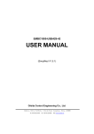
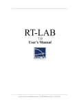
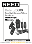
EMBC1000-USB1553B-1 User Manual (Simplified V 1.1) Orbita Control Engineering Co., Ltd. Add: Orbita TechPark, 1 Baisha Road, Zhuhai, Guangdong, China, 519080 Tel: +86-756-3391979 Fax: +86-756-3391980 Web:www.myorbita.net First published in 2008 by Orbita Control Engineering Co., Ltd. Zhuhai, China © Orbita Control Engineering Co., Ltd. All rights reserved. No part of this publication may be reproduced, stored in a retrieval system, or transmitted, in any form, or by any means, electronic, mechanical, photocopying, recording or otherwise, without prior permission, in writing, from Orbita Control Engineering Co. Ltd.(thereafter called “Orbita”). User’s Manual Information This document contains the simplified User Manual of EMBC1000-USB1553B-1 device. Orbita reserves the rights to make changes in the products or specifications contained in this document in order to supply the best possible products. Orbita does not assume responsibility for errors that may appear in this manual. Orbita also assumes no responsibility for the use of this device beyond the product specifications. Applications for any target hardware connections contained in this publication are for illustration purposes only and Orbita makes no representation or warranty that such applications will be suitable for the use specified without further testing or modification according to the target hardware specifications. The software associated with the shipped device shall not be used for other purpose except as stated in the terms of the software license agreement, or with special permission from Orbita. Special Notes EMBC, EIPC, S698, OBT429, OBT1553B, ORION are registered trademarks of Orbita Control Engineering Co. Ltd. Microsoft, Windows XP, Windows 2000 are registered trademarks of Microsoft Corporation. All other products mentioned in this User’s Manual are trademarks or registered trademarks of their respective manufacturers. Application of EMBC1000-USB1553B-1 EMBC1000-USB1553B-1 is a USB based device that provides new levels of performance and flexibility for systems interfacing to 1553B data bus, including data transmission, data receiving, real-time data display, data recording and replay, etc.. EMBC1000-1553B-1 User Manual CONTENTS CHAPTER 1 OVERVIEW .......................................................................................................... 1 1.1 ABOUT EMBC1000-USB1553B-1 ..................................................................................... 1 1.2 APPLICATIONS .................................................................................................................... 2 1.3 CHARACTERISTICS ............................................................................................................. 2 1.4 SYSTEM REQUIREMENTS .................................................................................................... 4 1.5 RESOURCES ON CD-ROM.................................................................................................. 4 1.6 SPECIAL HANDLINGS AND CAUTIONS ................................................................................... 5 CHAPTER 2 1553B BUS NETWORKING................................................................................ 6 2.1 INTERFACE DESCRIPTION .................................................................................................... 6 2.2 1553B CABLES AND CONNECTORS ..................................................................................... 8 2.3 1553B NETWORKING ......................................................................................................... 9 CHAPTER 3 OPERATION AND SETUP ................................................................................ 10 3.1 HARDWARE INSTALLATION ................................................................................................. 10 3.2 SOFTWARE DRIVER INSTALLATION ..................................................................................... 10 3.3 APPLICATION SOFTWARE INSTALLATION ............................................................................. 14 CHAPTER 4 APPLICATION SOFTWARE OPERATION ....................................................... 21 4.1 BUS CONTROL(BC).......................................................................................................... 22 4.1.1 Message Editor ....................................................................................................... 23 4.1.2 Frame Editor ........................................................................................................... 24 4.1.3 BC Setup................................................................................................................. 25 4.1.4 BC Run.................................................................................................................... 26 4.2 REMOTE TERMINAL(RT) RECEIVING .................................................................................. 27 4.2.1 RT Setup ................................................................................................................. 28 4.2.3 RT Run.................................................................................................................... 29 4.3 REMOTE TERMINAL(RT) TRANSMIT ................................................................................... 29 4.3.1 RT Setup ................................................................................................................. 30 4.3.2 RT Message Editor ................................................................................................. 30 4.3.3 RT Run.................................................................................................................... 31 4.4 BUS MONITOR(BM) ..................................................................................................... 32 4.4.1 BM Filter Options .................................................................................................... 33 4.4.2 BM Setup ................................................................................................................ 33 4.4.3 BM Run ................................................................................................................... 34 CHAPTER 5 DEVELOP YOUR APPLICATION SOFTWARE ................................................ 36 5.1 API LIBRARY .................................................................................................................... 36 5.2 FUNCTION DESCRIBE ........................................................................................................ 37 5.3 SAMPLES ......................................................................................................................... 39 CHAPTER 6 PRODUCT ORDERING INFO ........................................................................... 40 APPENDIX A: MIL-STD-1553B INTRODUCTION ................................................................. 41 Orbita Control Engineering Co., Ltd. -i- EMBC1000-1553B-1 User Manual A.1. MIL-STD-1553B DEFINED.............................................................................................. 41 A.2. HARDWARE ELEMENTS .................................................................................................... 42 A.2.1 Transmission Media................................................................................................ 42 A.2.2 Remote Terminals................................................................................................... 42 A.2.3 Bus Controller......................................................................................................... 42 A.2.4 Bus Monitor............................................................................................................. 42 A.3. PROTOCOL ..................................................................................................................... 43 A.3.1 Word Types............................................................................................................. 43 Orbita Control Engineering Co., Ltd. - ii - EMBC1000-USB1553B-1 User Manual Chapter 1 Overview 1.1 About EMBC1000-USB1553B-1 Figure 1-1 EMBC1000-USB1553B-1 Device The EMBC1000-USB1553B-1 is multi-protocol USB Device that provides new levels of performance and flexibility for systems that interface to a MIL-STD-1553B data bus. Each 1553 channel can emulate a Bus Controller, a Remote Terminal, or a Bus Monitor. EMBC1000- USB1553B-1 device is powered by an external power supply --- +12VDC power adaptor. The EMBC1000-USB1553B-1 device comes with driver software, API (Application Programming Interface) library and user oriented application software, running under Windows 2000, Windows XP. The user oriented application software has been designed with the capabilities of simulating the outputs of various airborne systems, receiving inputs from these systems. API library is also provided together with example source code (Visual C++), which allows users to easily develop their own application software or project. The manual uses Symbols and icons: Orbita Control Engineering Co., Ltd. -1- EMBC1000-USB1553B-1 User Manual The Warning icon presents information pertaining to hazards that will cause damage to the product and possible injury to the user. The Caution icon identifies important information that presents a possibility of damage to the product if not heeded. The Note icon signifies important supplementary information that will be useful to the user. 1.2 Applications EMBC1000-USB1553B-1 device is well suited for all types of ground support work (development, manufacturing test, on-site maintenance, etc.), as well as on-board data acquisition. LRU developers find that this device provides easy access for simulating and/or testing new systems prior to use with actual flight systems. Avionics maintenance and validation teams enjoy on-site testing and analysis with this device. It also used in sensor and control systems including prototype passenger cars, oil platforms subway control systems and the International Space Station. Figure 1-2 Wide Applications 1.3 Characteristics EMBC1000-USB1553B-1 device come in single-function configurations. Single-function Orbita Control Engineering Co., Ltd. -2- EMBC1000-USB1553B-1 User Manual device allow operation in only one of the three 1553 modes at a time: Bus Controller, Bus Monitor, or Remote Terminal (up to 31 RTs). Although all three modes are available, the board can operate only in one mode at one time. EMBC1000-USB1553B-1 device features with the following characteristics: z z z USB 2.0 or USB1.1 Interface with PC Supports the six major categories of message types: BC → RT RT → BC RT → RT Broadcast Mode code Broadcast Mode code Enhanced BC/RT/BM Architecture Supports MIL-STD-1553 A and B Notice 2 Transformer or Direct Coupled 1553B Channels 64K-bytes RAM One A/B Dual Redundant Mil-STD-1553 Channel Programmable selected one of BC、RT or BM mode Data Rate 1MHz Programmable Time Tag resolution Bus Controller ― Programmable Message automatic retries ― Programmable Frame Time ― Loop and Single-shot for BC operation ― Supports multiple Mode Codes ― Programmable Response time-out and late response ― Insert periodic messages into a running BC list ― Supports Error detection ― Supports Message Data and Status display ― Supports Setting options and Data saved Remote Terminal ― ― One RT simulation Programmable RT ID、Subaddress ID and Mode Code ID ― Programmable Status Word ― Programmable RT-RT response time ― Selectable Broadcast Mode ― Supports Setting options and Data saved Bus Monitor ― Capture 100% fully loaded bus traffic with: DATA、Time-tagging、 Error status、Word status、 Message status and response time ― Filtering by Subaddress、transmit or receive Orbita Control Engineering Co., Ltd. RT -3- EMBC1000-USB1553B-1 User Manual z z z z ― Individual DATA and COMMAND Stacks ― 32bit, microsecond resolution time-tagging Includes high-level API libraries for Windows 2000, XP and Source code USB1553B GUI bus analyzer provided Power:+12VDC:500mA Physical Size: 135mmx114mmx33mm(Length x Width X High) z Operating temperature range: -40℃~+85℃ 1.4 System Requirements For a single-user system, EMBC1000-USB1553B-1 requires the following: An IBM compatible PC equipped with USB 2.0 or USB1.1 Interface, Pentium processor 1.6GHz or better CPU, 2-Gbyte Minimum Hard Disk , 256-Mbyte Minimum RAM; CD-ROM drive, monitor, Windows XP or Windows 2000, etc.. Shall be required for installing the USB device and the associated software. A cable assembly is required to interface to the 1553B bus target hardware or other discrete channels. 1.5 Resources on CD-ROM The resources on CD-ROM include: Directory: G:\ (assume G:) \setup USB1553B.exe 1553DLL.dll 1553DLL.lib setup.exe data analysis executable file setup file \UserDesign \Include for user’s development use EMBCAPI.h \Lib 1553DLL.dll 1553DLL.lib \Samples \VC++ \BCDemo1 \RTDemo1 \BMDemo1 \Doc Orbita Control Engineering Co., Ltd. -4- EMBC1000-USB1553B-1 User Manual EMBC1000-USB1553B-1 User Manual.pdf User manual \Driver \WINDOWS \driver EMBC1000-USB1553B.sys EMBC1000-USB1553B.inf \training Video files to show the operations \BC.avi \RT.avi \BM.avi \INSTALL.avi 1.6 Special Handlings and Cautions Since EMBC1000-USB1553B-1 device uses state-of-the-art components and connectors, properly handlings and cares must be taken to ensure that the device will not be damaged by Electrical Static Discharge (ESD), physical shock, or improper power surges. • • • Turn off power to the PC completely; NEVER insert or remove device with power turned on; Ensure that standard ESD precautions are taken. At least, one hand should be grounded to the power supply in order to eliminate static potentials; • Do not store the device in environment exposed to excessive heat, magnetic fields or radiation. Orbita Control Engineering Co., Ltd. -5- EMBC1000-USB1553B-1 User Manual Chapter 2 1553B Bus Networking 2.1 Interface Description The EMBC1000-USB1553B-1 interface description as shown in Figure2-1 USB Interface RESET J1:1553B Bus Connector STATE LED POWER LED POWER Input Figure 2-1 Interface Description Power Input: +12VDC/500mA power adaptor input (the adaptor works between 100VAC and 240VAC). RESET: This key-press can be used to generate a system reset. LED Indication: POWER LED: Power indicator, GREEN or OFF GREEN color when power is ON, OFF when power to the device is ABNORMAL; STATUS LED: Device RUN status indicator, RED, Blinking RED, Blinking GREEN, BLUE or OFF Table 2-1 STATUS LED Description STATUS LED Description OFF Power Down or self-testing RED USB device has not been enumerated BLUE USB device has been enumerated Orbita Control Engineering Co., Ltd. failure -6- EMBC1000-USB1553B-1 User Manual Blinking GREEN 1553B communicate activity Blinking RED 1553B communicate error USB interface: Standard USB 2.0 and USB1.1 port J1: 1553B Bus Connector, Figure 2-2 show J1 and 1553B Connect Cable Figure 2-2 1553B Bus Connector and Cable C1 and C2 are TRB-0102 connector, Channel A and Channel B which can provide the link to outside 1553B network. Table 2-2 J1:1553B Bus Connector Pin Definition Pin Signal Direction Description 1 1553B_CHAN I/O MIL-STD-1553B bus driver A, negative signal 2 1553B_CHA I/O MIL-STD-1553B bus driver A, positive signal 3 GND 4 NC 5 NC 6 GND 7 NC 8 NC 9 GND POWER GND 10 GND POWER GND 11 GND POWER GND 12 GND POWER GND 13 1553B_CHB I/O MIL-STD-1553B bus driver B,positive signal 14 1553B_CHBN I/O MIL-STD-1553B bus driver B,negative signal 15 GND POWER GND POWER GND Orbita Control Engineering Co., Ltd. POWER GND -7- EMBC1000-USB1553B-1 User Manual EMBC1000-USB1553B-1 allows two software configurable bus coupling modes to connect it to the 1553B network: • Transformer coupling: it can provide better isolation over long distances and noise immunity, in this mode, the external transformer couplers are needed. • Direct coupling: this mode is often used in the laboratory and it do not require transformer couplers supported. But cable length less than 30 cm 2.2 1553B Cables and Connectors The cables used for 1553B bus and stub connections are two-conductor twisted pair wires with twin-axial connectors. Figure 2-3 1553B Cables and Connector Description For the twin-axial connector, the center pin is the POSITIVE signal (connect the blue conductor of 1553B cable), and the ring is the NEGATIVE signal (connect the white conductor of 1553B cable). The shield is connected to ground. Orbita Control Engineering Co., Ltd. -8- EMBC1000-USB1553B-1 User Manual 2.3 1553B Networking Figure 2-4 1553B Networks Orbita Control Engineering Co., Ltd. -9- EMBC1000-USB1553B-1 User Manual Chapter 3 OPERATION AND SETUP 3.1 Hardware Installation 1. Connect the EMBC1000-USB1553B device to PC with the USB cable 2. Turn on the power adaptor (+12VDC) 3. Insert the provided CD-ROM into you PC with Windows XP/2000, now you are ready to install the drivers onto your PC 4. After the device has been installed into your PC, turn off the power, you should assemble the 1553B cables, and built the link between your device and the 1553B network 3.2 Software Driver Installation When the hardware installation done, you need to install “Board oriented drivers” software from the provided CD-ROM, which are designed to run under Windows XP or Windows 2000. Once EMBC1000-USB1553B-1 device installed into your PC, and the computer is powered on, the PC will perform the detection for all new hardware, and the “Add Hardware Wizard” window will be opened automatically (Figure 3-1). Figure 3-1 Add Hardware Wizard window Orbita Control Engineering Co., Ltd. - 10 - EMBC1000-USB1553B-1 User Manual Choose “Yes, I have already connected the hardware”, then click the “Next” button, you will get: Figure 3-2 Welcome to the Found New Hardware Wizard Choose “Install from a list or specific location (Advanced)”, then click the “Next “button, you will be asked to choose: Orbita Control Engineering Co., Ltd. - 11 - EMBC1000-USB1553B-1 User Manual Figure 3-3 Please choose your search and installation options Choose “Don’t search. I will choose the driver to install”, then click the “Next” button, you will guide to: Figure 3-4 select a hardware type Choose “Show All Devices”, then click the “Next” button, you will be asked to select: Orbita Control Engineering Co., Ltd. - 12 - EMBC1000-USB1553B-1 User Manual Figure 3-5 Select the device driver Click”Have Disk…” you will get: Figure 3-6 Install From Disk Click”Browse...” button to locate the driver software “EMBC1000_USB553B_driver.inf” (you can find it on the CD-ROM, directory \Driver\WINDOWS\usb1553bDriver\), then click “OK” button, you will get: Figure 3-7 Select the device driver Click “Next” button, you will get: Orbita Control Engineering Co., Ltd. - 13 - EMBC1000-USB1553B-1 User Manual Figure 3-8 Finish Click on “Finish” button to complete this installation procedure. Congratulations! Now you have installed the “Board oriented drivers” onto your PC successfully. 3.3 Application Software installation Double click SETUP.EXE(you can find it on CD-ROM, \setup), then the setup initialization window will be opened, shown in Figure 3-9: Orbita Control Engineering Co., Ltd. - 14 - EMBC1000-USB1553B-1 User Manual Figure 3-9 Application Software setup initialization windows A moment later, the application software setup main window will be opened automatically, as shown in Figure 3-10. Figure 3-10 Setup main interface Click the “Next” button, then the “Software License agreement” window will be get, as shown in Figure 3-11 Orbita Control Engineering Co., Ltd. - 15 - EMBC1000-USB1553B-1 User Manual Figure 3-11 software License agreement Click “Next”, you will get the “User Information” window, Figure 3-12. Input any character Figure 3-12 User Information Fill in your own information, then click the “Next” button, you will get the “Choose Destination Location” window, Figure 3-13. Orbita Control Engineering Co., Ltd. - 16 - EMBC1000-USB1553B-1 User Manual Figure 3-13 Choose Destination Location Choose the location of the destination of the application software, then click the “Next” button, you will get the “setup type” window, as shown in Figure 3-14. Figure 3-14 Setup Type Choose a setup type, and then click “Next”, you will get the “Select Program Folder” Orbita Control Engineering Co., Ltd. - 17 - EMBC1000-USB1553B-1 User Manual window, as shown in Figure 3-15. Figure 3-15 Select Program Folder Fill in the “Program Folder”, and then click “Next”, the setup will be started, as shown in Figure 3-16. Orbita Control Engineering Co., Ltd. - 18 - EMBC1000-USB1553B-1 User Manual Figure 3-16 Setup in progress When the setup is done, the “Setup Complete” window will be opened automatically, shown in Figure 3-29, you can click the “Finish” button to complete this installation procedure. Congratulations! Now you have installed the application software of EMBC1000-USB1553B-1 onto your PC successfully. Orbita Control Engineering Co., Ltd. - 19 - EMBC1000-USB1553B-1 User Manual Figure 3-18 setup finish Orbita Control Engineering Co., Ltd. - 20 - EMBC1000-USB1553B-1 User Manual Chapter 4 Application Software Operation When the Application Software Installation done, Double click USB1553B.EXE(you can find it on Desktop), then the “Device Setup” window will be opened, shown in Figure 4-1: Device type Options Invalidation Options Coupling Options Figure 4-1 EMBC1000-USB1553B Device Setup Click the “OK” button, you will get USB1553B Main Window, Figure 4-2: USB1553B Main Window screen is split into four sections. These sections consist of the Topic Bar, Menu Bar, Tools Bar, Working Editor. Orbita Control Engineering Co., Ltd. - 21 - EMBC1000-USB1553B-1 User Manual Topic Bar Menu Bar Tools Bar Working Editor Figure 4-2 USB1553B Main Window 4.1 Bus Control(BC) Double-click (you can find it on the “USB1553B Main Window”),then the “BC Main Widow” window will be opened, shown in Figure 4-3: The Bus Controller mode provides the ability to create valid MIL-STD-1553B bus controller messages by simple parameter selection in a major and minor message data format. BC Operation Steps including: a. Message Editor b. Frame Editor c. BC Setup d. BC Run Orbita Control Engineering Co., Ltd. - 22 - EMBC1000-USB1553B-1 User Manual Messages Editor Tool-bar Frame Editor Figure 4-3 BC Main Window 4.1.1 Message Editor Next, click the icon; you will get Figure 4-4: Message Name Data Words Counts Set Data words Contents Set Command Words Contents Figure 4-4 BC Message Editor Orbita Control Engineering Co., Ltd. - 23 - EMBC1000-USB1553B-1 User Manual BC Message Editor Steps: 1) Create Message Name 2)Set Data Words Counts 3)Set Data Words Contents 4) Set Command Words Contents. It allows for the selection of the destination Remote Terminal address and subaddresses, channel (A or B) selection and transmit message types. Transmit message types consist of BC to RT Transfer, RT to BC Transfer, RT to RT Transfer, Mode Code, Broadcast, and Broadcast Mode Code. , to saving the message and create new the message. Next, click 4.1.2 Frame Editor Frame editing is accomplished via selection of previously created messages in the Message Name and adding or inserting them to the Frames list. Figure 4-5 shows Message1 are added to the list with the Add . To add a message to the list, select the message to be added from the Message list and click on the Add . is used to swap two messages of your frame. delete messages of your frame. Orbita Control Engineering Co., Ltd. is used to is used to repeat your frame. - 24 - EMBC1000-USB1553B-1 User Manual Figure 4-5 Frame Editor 4.1.3 BC Setup Double-click (you can find it on the “Frame Editor” Window ),then the “BC Setup” window will be opened, shown in Figure 4-6: This screen has been designed to provide the user with the ability to setup the Bus Controller parameters needed in controlling response timing time tag resolution and error handling. When the Retry Enable, Retry (Single or Double) option selects whether the Bus Controller will do a Single or a Double retry on message errors. Change-Channel option selects whether the Bus Controller will change channel retry at Single retry. Change-Channel (1st) and Change-Channel (2nd) option select whether the Bus Controller will change channel at First retry or at Second retry. Orbita Control Engineering Co., Ltd. - 25 - EMBC1000-USB1553B-1 User Manual Figure 4-6 BC Setup 4.1.4 BC Run Double-click (you can find it on the “Frame Editor” Window ),then the “BC Run” window will be opened, shown in Figure 4-7: The Save Frame Option section used to select Frame information is being stored or not. The Save Frame, which will be examined in greater detail later, contains detailed information about the MIL-STD-1553B bus activity which has already taken place. In the stack section of this screen, the file name that was selected upon entry into this screen is displayed. This is the file which will hold the Communication Stack for later display and use. Next, if you want open this file please click Orbita Control Engineering Co., Ltd. icon. - 26 - EMBC1000-USB1553B-1 User Manual BC run status display Data Contents Save Frame option Return BC Main window BC Run and Stop button Figure 4-7 BC Run Status Display 4.2 Remote Terminal(RT) Receiving Double-click (you can find it on the “USB1553B Main Window”),then the “RT Main Widow” window will be opened, shown in Figure 4-8: RT Receiving Operation Steps including: a. RT Setup b. RT Run Orbita Control Engineering Co., Ltd. - 27 - EMBC1000-USB1553B-1 User Manual RT Editor Tool-bar Figure 4-8 RT Main Window 4.2.1 RT Setup Double-click (you can find it on the “RT Main Window”),then the “RT Receiving Setup” window will be opened, shown in Figure 4-9: RT Address set Enable or Disable Model code Time Tag Time Resolution Set Invalidation Options RT Return Status Word set Orbita Control Engineering Co., Ltd. - 28 - EMBC1000-USB1553B-1 User Manual Figure 4-9 RT Receiving Setup 4.2.3 RT Run Double-click (you can find it on the “RT Receiving Setup” Window ),then the “RT Run” window will be opened, shown in Figure 4-10. Next, Click Receiving RT Status ,then RT is active. RT Receiving Data Save RT Result option Return RT Main window RT Run and Stop button Figure 4-10 RT Receiving Run 4.3 Remote Terminal(RT) Transmit Double-click (you can find it on the “USB1553B Main Window”),then the “RT Main Widow” window will be opened, shown in Figure 4-8: RT transmit Operation Steps including: a. RT Setup b. RT Message Editor c. RT Run Orbita Control Engineering Co., Ltd. - 29 - EMBC1000-USB1553B-1 User Manual 4.3.1 RT Setup Double-click (you can find it on the “RT Main Window”),then the “RT Transmit Setup” window will be opened, shown in Figure 4-11: RT Address(31~ 0) Setup Invalidation Options Time Tag Time Resolution Set RT-RT Response Timeout Set RT Return Status Word Figure 4-11 RT Transmit Setup 4.3.2 RT Message Editor Double-click (you can find it on the “RT Main Window”),then the “RT Message Editor” window will be opened, shown in Figure 4-12: Orbita Control Engineering Co., Ltd. - 30 - EMBC1000-USB1553B-1 User Manual Message Name Set Data words Contents Data Words Counts Figure 4-12 RT Message Editor RT Message Editor Steps: 1) Create Message Name 2)Set Data Words Counts 3)Set Data Words Contents , to saving the message and create new the message. Next, click 4.3.3 RT Run Double-click (you can find it on the “RT Receiving Setup” Window ),then the “RT Run” window will be opened, shown in Figure 4-13. Next, Click Orbita Control Engineering Co., Ltd. ,then RT is active. - 31 - EMBC1000-USB1553B-1 User Manual Transmit RT Status RT Data Display Save RT Result option Return RT Main window RT Run and Stop button Figure 4-13 RT Transmit Run 4.4 Bus Monitor(BM) Double-click (you can find it on the “USB1553B Main Window”),then the “BM Main Widow” window will be opened, shown in Figure 4-14: BM Operation Steps including: a. BM Filter Options b. BM Setup c. BM Run Orbita Control Engineering Co., Ltd. - 32 - EMBC1000-USB1553B-1 User Manual 4.4.1 BM Filter Options Tool-bar RT Subaddress Filter Option, This option selects is not filter. Figure 4-14 BM Main Window 4.4.2 BM Setup Double-click (you can find it on the “BM Main Window” Window ),then the “BM Setup” window will be opened, shown in Figure 4-15: This screen has been designed to provide the user with the ability to setup the Bus Monitor parameters needed in controlling response timing time tag resolution. Orbita Control Engineering Co., Ltd. - 33 - EMBC1000-USB1553B-1 User Manual Figure 4-15 BM Setup 4.4.3 BM Run Double-click (you can find it on the “BM Main Window” Window), and then the “BM Run” window will be opened, shown in Figure 4-16. Next, Click Orbita Control Engineering Co., Ltd. ,then BM is active. - 34 - EMBC1000-USB1553B-1 User Manual BM Status Save BM Result option RT Run and Stop button Return BM Main window Figure 4-16 BM Run Orbita Control Engineering Co., Ltd. - 35 - EMBC1000-USB1553B-1 User Manual Chapter 5 Develop Your Application Software To allow the user to develop his own application software or project, EMBC1000-USB1553B-1 device comes with software drivers, API (Application Programming Interface) library and user oriented application software, running under Windows 2000 or Windows XP. The user oriented application software has been designed with the capabilities of simulating the outputs of various airborne systems, receiving inputs from these systems, and providing bus data analysis functions. API library is also provided together with example source code (Visual C++), which allows users to easily develop their own application software or project based on the real world applications. 5.1 API Library When you begin to develop your own application software for this USB device, you should finish the settings below in you project (build in Visual C++ 6.0): Copy 1553DLL.dll、1553DLL.lib、1553BUSBhead.h (you can find them on CD-ROM \setup\UserDesign\Lib) to your project working directory. Add the 1553DLL.lib to the project: ProjectÆSettingÆLink, as shown in Figure 5-1. Figure 5-1 Add the 1553DLL.lib to the project Edit the head file; refer to the source code below: #include "1553BUSBhead.h " Orbita Control Engineering Co., Ltd. - 36 - EMBC1000-USB1553B-1 User Manual Now the API setup is done. When you build your project, VC++ will link the APIs automatically and add them to your project. 5.2 Function Describe 1. USB1553B_Init function BOOL USB1553B_Init(int Coupling) Purpose initialization parameter Return Coupling:0-Direct Coupling ,1-Transformer Coupling true-succeed false -fault 2. Set_BoardMode function void Set_BoardMode(int mode) Purpose Set EMBC1000-USB1553B Mode parameter Mode:(BCMODE/RTMODE/BMMODE) Return NULL 3. Set_BCInit function void Set_BCInit(int enable_retry,int change2,int timeout,int time_precision) Purpose Initialize Bus Controller Mode parameter enable_retry: 0-enable,1-disable retry_num: 0-single,1-double change1、 change2: 0-disable change,1-enable change timeout: 0-18.5 uS,1-22.5uS,2-50.5 uS,3-128 uS time_precision: 0-1uS,1-2uS,2-4uS,3-8uS,4-16uS,5-32uS,6- 64uS,7-128uS. Return retry_num,int change1,int NULL 4. Set_RTInit function void Set_RTInit(int timeout,int time_precision,int rt_address,int subsys,int dynbus,int terflag,int service,int busy,int cleartt,int loadtt,int rxmode16) Orbita Control Engineering Co., Ltd. - 37 - EMBC1000-USB1553B-1 User Manual Purpose RT initialization parameter timeout: 0-18.5 uS,1-22.5uS,2-50.5 uS,3-128 uS time_precision: 0-1uS,1-2uS,2-4uS,3-8uS,4-16uS,5-32uS,6- 64uS,7-128uS. rt_address: 0x00 ~ 0x1F subsys: 0-false,1-true dynbus: 0-false,1-true terflag: 0-false,1-true service: 0-false,1-true busy: 0-false,1-true cleartt: 0-false,1-true loadtt: 0-false,1-true rxmode16: 0-false,1-true Return NULL 5. Set_BMInit function void Set_BMInit(int* time_precision) Purpose BM initialization parameter Transmit_SA: 1-enable,0-disable Receive_SA:1-enable,0-disable timeout: 0-18.5 uS,1-22.5uS,2-50.5 uS,3-128 uS time_precision: 0-1uS,1-2uS,2-4uS,3-8uS,4-16uS,5-32uS,6- 64uS,7-128uS. Return Transmit_SA,int* Receive_SA,int timeout,int NULL 6. Send_BCData function void Send_BCData(BC_MsgBlock &BC_Msg) Purpose BC mode ,write a message to EMBC1000-USB1553B memory parameter BC_Msg :the struct of BC Message Return NULL 7. Read_BCdata function int Read_BCdata(int msgnum,BC_STATUS &BC_set) Orbita Control Engineering Co., Ltd. - 38 - EMBC1000-USB1553B-1 User Manual Purpose BC mode ,read single message parameter msgnum:message number(0-63) BC_set :the pointer of message struct Return 1-succeed 0-fault 8. Send_RTData function void Send_RTData(unsigned int *RTdata,int msgnum) Purpose Write data to designate address parameter msgnum : designate sa-address RTdata: pointer of data memory Return NULL 9. Read_RTdata function int Read_RTdata(RT_STATUS &RT_set) Purpose RT mode,read single message parameter RT_set : message struct pointer Return 1-succeed 0-fault 10. Read_BMdata(BM_STATUS &BM_set) function int Read_BMdata(BM_STATUS &BM_set) Purpose BM mode,read single message parameter BM_set : message struct pointer Return 1-succeed 0-fault 5.3 Samples This example source code will show you how to use the API. You can get the details from the CD-ROM (G:\Samples) directory. (VC++ 6.0 environment), Orbita Control Engineering Co., Ltd. - 39 - EMBC1000-USB1553B-1 User Manual Chapter 6 PRODUCT ORDERING INFO Table 6-1 Product ordering information Product Number Description Single-function boards allow operation in only one of the three 1553 modes at a time: Bus Controller, Bus Monitor, or EMBC1000-1553B-1 Remote Terminal (up to 31 RTs). Although all three modes are available, the board can operate only in one mode at any one time. Orbita Control Engineering Co., Ltd. Baud rate Software support Windows 2000 or 1Mbps Windows XP based drivers and application software - 40 - EMBC1000-USB1553B-1 User Manual Appendix A: MIL-STD-1553B Introduction A.1. MIL-STD-1553B Defined So now that we understand the driving need for the development of a data bus, and a little of its history and application, what exactly is MIL-STD-1553B/A summary of the characteristics of MIL-STD-1553B is found in Table A-1. Table A-1. Summary of MIL-STD-1553 Characteristics The primary purpose of the data bus is to move data between black boxes. How these boxes are connected and the methodology with which the communication is accomplished is central to the operation of the data bus. However, before we delve into the protocol, it is necessary to understand a little of the data bus hardware. Orbita Control Engineering Co., Ltd. - 41 - EMBC1000-USB1553B-1 User Manual A.2. Hardware Elements MIL-STD-1553 defines certain aspects regarding the design of the data bus system and the black boxes to which the data bus is connected. The standard defines four hardware elements. They are: • • • • The transmission media Remote terminals. Bus controllers. Bus monitors. A.2.1 Transmission Media The transmission media, or data bus, is defined as a twisted shielded pair transmission line consisting of the main bus and a number of stubs. There is one stub for each terminal connected to the bus. The main data bus is terminated at each end with a resistance equal to the cable's characteristic impedance (plus or minus two percent). This termination makes the data bus behave electrically like an infinite transmission line. A.2.2 Remote Terminals Remote terminals are defined within the standard as “All terminals not operating as the bus controller or as a bus monitor”. Therefore if it is not a controller, monitor, or the main bus or stub, it must be a remote terminal. The remote terminal comprises the electronics necessary to transfer data between the data bus and the subsystem. So what is a subsystem. For 1553 applications, the subsystem is the sender or user of the data being transferred. A.2.3 Bus Controller The bus controller is responsible for directing the flow of data on the data bus. While several terminals may be capable of performing as the bus controller, only one bus controller may be active at a time. The bus controller is the only one allowed to issue commands onto the data bus. The commands may be for the transfer of data or the control and management of the bus (referred to as mode commands). A.2.4 Bus Monitor A bus monitor is a terminal that listens (monitors) to the exchange of information on the data bus. The standard strictly defines how bus monitors may be used, stating that the information obtained by a bus monitor be used “for off-line applications (e.g., flight test recording, maintenance recording or mission analysis) or to provide the back-up bus controller sufficient information to take over as the bus controller.” A monitor may collect all the data from the bus or may collect selected data. The reason for restricting its use is that while a monitor may collect data, it deviates from the command-response protocol of the Orbita Control Engineering Co., Ltd. - 42 - EMBC1000-USB1553B-1 User Manual standard, in that a monitor is a passive device that doesn’t transmit a status word and therefore cannot report on the status of the information transferred. Bus monitors fall into two categories: • • A recorder for testing. A terminal functioning as a back-up bus controller. A.3. Protocol Now that you understand a little of the hardware requirements, it’s time to discuss the methodology by which the information transfer occurs. The rules under which the transfers occur are referred to as “protocol”. The control, data flow, status reporting, and management of the bus are provided by three word types. A.3.1 Word Types Three distinct word types are defined by the standard. They are: • • • Command words. Data words. Status words. Each word type has a unique format, yet all three maintain a common structure. Each word is twenty bits in length. The first three bits are used as a synchronization field, thereby allowing the decode clock to re-sync at the beginning of each new word. The next sixteen bits are the information field and are different between the three word types. The last bit is the parity bit. Parity is based on odd parity for the single word. The three word types are shown in Figure A-1. Orbita Control Engineering Co., Ltd. - 43 - EMBC1000-USB1553B-1 User Manual Figure A-1 1553B Word Formats Orbita Control Engineering Co., Ltd. - 44 -