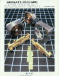
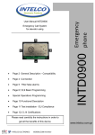
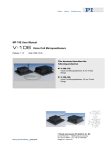
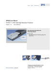
1
MP 35E User Manual M-405 / M-410 / M-415 Series Linear Positioning Stages Release: 3.3.3 Date: 2008-03-17 This document describes the following product(s): M-405.DG, M-410.DG, M-415.DG Linear Positioning Stages, DC-Motor gearhead M-405.CG, M-410.CG, M-415.CG Linear Positioning Stages, DC-Motor gearhead M-405.PD, M-410.PD, M-415.PD Linear Positioning Stages, with integrated amplifier (PWM) M-405.2S, M-410.2S, M-415.2S Linear Positioning Stages, stepper motor M-405.M0, M-410.M0, M-415.M0 Linear Positioning Stages, manual operation © Physik Instrumente (PI) GmbH & Co. KG Auf der Römerstr. 1 ⋅ 76228 Karlsruhe, Germany Tel. +49-721-4846-0 ⋅ Fax: +49-721-4846-299 [email protected] ⋅ www.pi.ws Declaration of Conformity according to ISO / IEC Guide 22 and EN 45014 Manufacturer: Manufacturer´s Address: Physik Instrumente (PI) GmbH & Co. KG Auf der Römerstrasse 1 D-76228 Karlsruhe, Germany The manufacturer hereby declares that the product Product Name: Model Numbers: Product Options: M-405/M-410/M-410 Series Translation Stages M-405, M-410, M-415 all model types complies with the following European directives: 73/23/EEC, Low voltage directive 89/336/EEC, EMC-Directive73/23/EWG, Niederspannungsrichtlinie / 98/37/EG, Maschinenrichtlinie / 98/37/EC, Machinery Directive The applied standards certifying the conformity are listed below. Electromagnetic Emission: EN 61000-6-3, EN 55011 Electromagnetic Immunity: EN 61000-6-1 Safety (Low Voltage Directive): EN 61010-1 Safety of Machinery: EN 12100 October 30, 2006 Karlsruhe, Germany Dr. Karl Spanner President Physik Instrumente (PI) GmbH & Co. KG is the owner of the following company names and trademarks: PI®, PIC®, ActiveDrive™ Copyright 1999–2008 by Physik Instrumente (PI) GmbH & Co. KG, Karlsruhe, Germany. The text, photographs and drawings in this manual enjoy copyright protection. With regard thereto, Physik Instrumente (PI) GmbH & Co. KG reserves all rights. Use of said text, photographs and drawings is permitted only in part and only upon citation of the source. Document Number MP 35E, Release 3.3.3 M-405_M-410_M-415_UserMP35E332.doc This manual has been provided for information only and product specifications are subject to change without notice. About This Document Users of This Manual This manual is designed to help the reader to install and operate the M-405 / M-410 / M-415 Series Linear Positioning Stages. It assumes that the reader has a fundamental understanding of basic servo systems, as well as motion control concepts and applicable safety procedures. The manual describes the physical specifications and dimensions of the M-405 / M-410 / M-415 Series Linear Positioning Stages as well as the procedures which are required to put the associated motion system into operation. This document is available as PDF file. Updated releases are available for download from www.pi.ws or by email: contact your Physik Instrumente Sales Engineer or write [email protected]. Conventions The notes and symbols used in this manual have the following meanings: WARNING Calls attention to a procedure, practice or condition which, if not correctly performed or adhered to, could result in injury or death. CAUTION Calls attention to a procedure, practice, or condition which, if not correctly performed or adhered to, could result in damage to equipment. NOTE Provides additional information or application hints. Related Documents The motion controller and the software tools which might be delivered with M-405 / M-410 / M415 Series Linear Positioning Stages are described in their own manuals. All documents are available as PDF files.. For updated releases visit download section of the PI Website (www.pi.ws), contact your Physik Instrumente Sales Engineer or write [email protected]. ! Contents 1 Introduction 1.1 1.2 1.3 1.4 1.5 2 Safety Precautions .................................................................... 5 Prescribed Use .......................................................................... 5 Model Survey............................................................................. 6 Contents of Delivery .................................................................. 7 Unpacking.................................................................................. 7 Installation 2.1 2.2 2.3 Interconnecting the System ....................................................... 9 Host PC ..................................................................................... 9 3.3 Maintenance ............................................................................ 13 4.3 M-4xx.CG Stages ..................................................................... 15 M-4xx.DG Stages ..................................................................... 16 M-xx.PD Stages........................................................................ 17 M-xx.2S Stepper Motor Stages ................................................ 18 Z-Axis Mounting Bracket .......................................................... 19 PIN Assignments ..................................................................... 20 4.3.1 4.3.2 4.3.3 4.4 M-4xx.CG, M-4xx.DG ............................................................... 20 M-4xx.PD PWM ........................................................................ 21 M-4xx.S1 Stepper Motors......................................................... 22 Disposal................................................................................... 22 Appendix I: Current Controllers 5.1 www.pi.ws 14 Specifications .......................................................................... 14 Dimensions.............................................................................. 15 4.2.1 4.2.2 4.2.3 4.2.4 4.2.5 5 DC-Motor Versions ................................................................... 11 Stepper Motor Versions............................................................ 11 Limit Switches........................................................................... 12 Reference Switch ..................................................................... 12 Technical Data 4.1 4.2 10 PWM Amplifiers & Brake Signal .............................................. 10 Motion Polarity, Limit & Reference Sensors ............................ 11 3.2.1 3.2.2 3.2.3 3.2.4 4 Cable Connector Position........................................................... 8 Attachment ................................................................................. 8 Operational Considerations 3.1 3.2 8 Mechanical Mounting................................................................. 8 2.1.1 2.1.2 3 3 23 Stepper Motor Controller ......................................................... 23 M-405 / M-410 / M-415 Series MP 35E Release 3.3.3 Page 1 Contents 5.2 DC-Motor Controllers............................................................... 24 5.2.1 5.2.2 6 Parameter Settings for C-863 Mercury™ ................................. 25 Parameter Settings for Other DC-Motor Controllers ................ 26 Appendix II: Older Controllers 6.1 6.2 Discontinued Stepper Motor Controllers.................................. 27 Discontinued DC-Motor Controllers......................................... 28 6.2.1 6.2.2 6.2.3 6.2.4 www.pi.ws 27 Parameter Settings for C-842 PC ISA-Bus Card ..................... 29 Parameter Settings for Older C-848s & C-880s....................... 29 Parameter Settings for C-844................................................... 30 Parameter Settings for C-862 Mercury..................................... 31 M-405 / M-410 / M-415 Series MP 35E Release 3.3.3 Page 2 Introduction 1 Introduction Fig. 1: M-415.DG, M-410.DG and M-405.DG Translation Stages (from left to right) M-405 / M-410 / M-415 Series Linear Positioning Stages are leadscrew driven stages with a travel range of 50, 100 and 150 mm. Precision crossed roller bearings guarantee straightness of travel of better than 2 µm / 100 mm. The stage base is precision machined from high-density, stress relieved aluminum for exceptional stability and minimum weight. Motorized versions are available with high resolution DC-motors with and without gearhead drives, and with stepper motors. NOTE In this manual, the designation “M-4xx” will be used to mean “M405 / M-410 / M-415”. Note that M-403 and other similarly numbered stage families are covered in other manuals. Models M-4xx.DG (DC-motor gearhead drive) use closed loop DC motors with shaft mounted position encoders and backlash-free gearheads providing 0.1 µm minimum incremental motion. Models M-4xx.PD (DC-motor direct drives) are equipped with 30-watt Active Drive DC motors providing 0.25 µm minimum incremental motion and velocity up to 15 mm/sec. The active drive concept features an integrated, high-efficiency power amplifier and reduces overall system cost, because the stage can be driven directly from PI motor controllers. Models M-4xx.2S use a high-resolution stepper motor allowing for 0.1 µm incremental motion in conjunction with a C-663 stepper motor controller. www.pi.ws M-405 / M-410 / M-415 Series MP 35E Release 3.3.3 Page 3 Introduction All stages are equipped with magnetic origin sensors and end of travel sensors. M-405 / M-410 / M-415 Series stages can be cross-stacked and combined with the M-592.00 Z-axis mounting bracket to provide multiaxis motion. Fig. 2: M-400 with stepper motor M-400 Features www.pi.ws Travel Ranges to 150 mm Stress-Relieved Aluminum Stage Base for Highest Stability Crossed Roller Bearings High-Resolution DC and Stepper Motor Drives ActiveDrive™ Concept Manual Knob for Convenient Position Adjustment Non-Contact Origin and Limit Switches M-405 / M-410 / M-415 Series MP 35E Release 3.3.3 Page 4 Introduction 1.1 Safety Precautions Before operating M-400 Series Linear Stages, read this: CAUTION ! M-400 stages are motorized by powerful electrical motors and can generate high forces due to gearhead transmission. Be aware that automatic limit switch halt may not be supported by the motor control electronics. Be aware that failure of the motor controller may drive the stage into a hard stop with high forces. When the stage is connected to the motor controller be aware that the stage could start an undesired move due to whatever reason. Be aware that overlength mounting screws will interfere with motion and may cause permanent damage! WARNING To avoid injury, do not put any parts in the gap between the moving stage and the motor cabin. Never put your finger at a place where the moving platform or any connected object could possibly trap it. 1.2 Prescribed Use Correct operation of the M-405 / M-410 / M-415 Series Linear Positioning Stages is only possible in combination with a suitable controller/driver (ordered separately) and software. The controlling device must be able to read out and process the signals from reference and limit switches and the incremental position encoder to ensure proper performance of the servo-control system. Based on their design and realization, these stages are intended for single-axis positioning, adjusting and shifting of loads at various velocities. M-405 / M-410 / M-415 Series Linear Positioning Stages can be mounted horizontally or vertically. To achieve the specified guiding accuracy, the positioners have to be mounted on a flat surface to avoid torsion of the basic profile. The positioners may only be used for applications suitably in accordance with the device specifications. www.pi.ws M-405 / M-410 / M-415 Series MP 35E Release 3.3.3 Page 5 Introduction Respect the safety instructions given in this User Manual. The operator is responsible for the correct installation and operation of the stages. The verification of the technical specifications by the manufacturer does not imply the validation of complete applications. In fact the operator is responsible for the process validation and the appropriate releases. The M-405 / M-410 / M-415 Series Linear Positioning Stages meet the specifications as defined by DIN EN 61010 for safe operation under normal ambient conditions. See the specifications table for details. 1.3 Model Survey 2 2.0 0.7 2 2.3 M-415.CG 150 69.12 0.0035 0.2 0.7 2 2.7 M-405.DG 50 29.642 0.0085 0.2 1.5 3 2.1 M-410.DG 100 29.642 0.0085 0.2 1.5 3 2.4 M-415.DG 150 29.642 0.0085 0.2 1.5 3 2.8 [W] 0.7 0.2 Mass [kg] 0.2 0.0035 Motor Power Max. Velocity 0.0035 69.12 [mm/s] Repeatability uni- 69.12 100 [µm/count] Design Resolution 50 M-410.CG [mm] M-405.CG Travel Range Gearhead Ratio The following table summarizes the most important characteristics of the M-405 / M-410 / M-415 Series Linear Positioning Stages available: DC motor gearhead Integrated PWM amp M-405.PD 50 0.125 0.2 15 30 2.1 M-410.PD 100 0.125 0.2 15 30 2.4 M-415.PD 150 0.125 0.2 15 30 2.8 Stepper Motor M-405.2S 50 - 0.025 0.2 6 2.1 M-410.2S 100 - 0.025 0.2 6 2.4 M-415.2S 150 - 0.025 0.2 6 2.8 Manual operation M-405.M0 50 not applicable 1.9 M-410.M0 100 not applicable 2.2 M-415.M0 150 not applicable 2.5 For complete technical data see the table on p. 4. www.pi.ws M-405 / M-410 / M-415 Series MP 35E Release 3.3.3 Page 6 Introduction 1.4 Contents of Delivery M-400 series stages are delivered with: 1.5 4 metric screws M4x30, w. hex wrench, (purpose: mounting two stages as an XY combination). Connecting cable (motorized stages only) This document, MP 35E (User Manual) Unpacking Unpack the stage with care. Compare the contents against the items covered by the contract and against the packing list. Inspect the contents for signs of damage. If parts are missing or you notice signs of damage, such as loose contacts or hairline cracks, please contact PI immediately. Save all packing materials in case the product need be shipped again. www.pi.ws M-405 / M-410 / M-415 Series MP 35E Release 3.3.3 Page 7 Installation 2 Installation 2.1 Mechanical Mounting WARNING—CRUSH HAZARD When mounting the stage keep in mind that the motor will move with the platform and possibly might trap your finger or any equipment! Make sure that there is sufficient clearance for the motor when it and the platform move. 2.1.1 Cable Connector Position Before mounting one of the motorized versions, decide whether or not the cable connector is in a suitable position. To change connector orientation, loosen the 2 set screws which clamp the motor housing with a 2 mm Allen wrench (shown) and rotate the housing and connector to the desired position (arrows). Then retighten the set screws. NOTE Motor may be rotated about its axis as desired to change cable connector orientation (Fig. 3). Fig. 3: Changing connector orientation 2.1.2 Attachment M-405 / M-410 / M-415 Series Linear Positioning Stages can be mounted in any orientation, horizontally or vertically. To achieve the specified guiding accuracy, the stages have to be mounted on even surfaces to avoid torsion of the basic profile. If necessary, use the clearance holes in the platform to access the mounting holes in the stage base. The platform can be moved with the knurled knob for this purpose. www.pi.ws M-405 / M-410 / M-415 Series MP 35E Release 3.3.3 Page 8 Installation Adapter plates and mounting brackets are available for stacking stages to form XY- or XYZ-systems. See p. 19 and the PI catalog at www.pi.ws for more information, or contact your PI Sales Engineer. To mount an object on the platform, use the threaded mounting holes and M4 screws. CAUTION ! Be aware that overlength mounting screws will interfere with motion and may cause permanent damage! 2.2 Interconnecting the System Motorized versions of the M-405 / M-410 / M-415 Series can be internetworked other PI micropositioning stages in many different combinations, including: 2.3 Mercury Class devices can be daisy chained off a single RS232 or USB port, meaning that even stepper and DC motors (PWM and analog) can be networked together (with C-663 and C-863 controllers) PWM and DC-motor devices can be mixed on the current models of the multi-axis controllers (with C-843, C-848, C-880). Host PC Most PI controllers are in turn controlled by a host PC provided by the user. The only exceptions are programmable controllers with standalone mode (C-862 Mercury), controllers with a joystick port or manual control pad. The controller is either installed directly in the PC (e.g. C-843) or connected to it over a communications interface. See the controller User Manual for details. PI generally provides software and/or drivers that run on the host PC to control the system. Typically there will be a control program with a graphic user interface for testing and simple operation, and, in addition, DLL, COM and/or LabView drivers for users who wish to use custom software. If the controller is a PC ISA or PCI card, there will also be hardware drivers to install. See the controller User and Software manuals for installation details. www.pi.ws M-405 / M-410 / M-415 Series MP 35E Release 3.3.3 Page 9 Operational Considerations 3 Operational Considerations 3.1 PWM Amplifiers & Brake Signal The .PD-version stages with the ActiveDrive™, direct, DC-motor drive have the platform connected directly to the 30-watt DC motor by a flexible coupling. For maximum dynamic performance, the DC servomotors are driven by high-efficiency PWM power amplifiers integrated into the stages. An external plug-in power supply is provided to supply the built-in amplifiers directly. This architecture allows high torque and high velocities while loading the motor controller with control signals only. The actual power is provided by the external supply. All current PI controllers can drive either analog or PWM stages by operating in the corresponding mode. NOTE Be sure your software turns the brake OFF before operation, even though standard M-4xx series stages are not equipped with brakes. If the signal on the brake line from the motor controller (pin 1) is in the Brake ON state (0 V), the PWM amplifier output to the motor is disabled and no motion is possible. www.pi.ws M-405 / M-410 / M-415 Series MP 35E Release 3.3.3 Page 10 Operational Considerations 3.2 Motion Polarity, Limit & Reference Sensors 3.2.1 DC-Motor Versions Positive Travel Direction Fig. 4: DC-motor versions NOTE Limit and reference signal polarities on DC and stepper motor versions are reversed 3.2.2 Stepper Motor Versions Positive Travel Direction Fig. 5: Stepper motor versions www.pi.ws M-405 / M-410 / M-415 Series MP 35E Release 3.3.3 Page 11 Operational Considerations 3.2.3 Limit Switches All M-405 / M-410 / M-415 Series motorized stages are equipped with non-contacting, Hall-effect limit switches (with TTL drivers). On stepper-motor versions, limit switch outputs are active low, on other versions, active high. Each limit switch controls an overtravel signal on its own dedicated line to the controller. It is the controller that is then responsible for stopping motion. If it does not do so in time, the stage will run into the hard stop. Should this happen, it may be necessary to push the stage manually out of the end zone. CAUTION High-speed crashes can cause irreparable damage. Do not disable limit switches in software. Test limit switch operation at low speeds. Type: Magnetic (Hall Effect) sensors Power supply. +5V / GND supplied by the motor controller through the motor connector. Voltage output: TTL level Sink / Source capability. ± 48 mA Logic: DC-motor versions: Active high, normal motor operation: low, limit switch hit: high Stepper motor versions: Active low, normal motor operation: high, limit switch hit: low 3.2.4 Reference Switch Motorized versions are equipped with direction-sensing Hall-effect reference switches. These switches provide a TTL signal indicating whether the stage is to the positive or negative side of a fixed point. The rising or falling edge of this signal can be used as to indicate a known reference position (always approach the reference point from the same side to achieve repeatability; the difference in the reference points when approached from the positive side and from the negative side is about 0.3 mm to 0.5 mm). See the controller User Manual and/or associated software manuals for the commands which make use of the reference signal. See Fig. 4 and Fig. 5 for location details. www.pi.ws M-405 / M-410 / M-415 Series MP 35E Release 3.3.3 Page 12 ! Operational Considerations Average reference position accuracy: 0.3 µm Motor controllers with GCS command set (C-843, C-880, C-848, as well as C-862, C-863 and C-663 when used with GCS software) approach the reference sensor always from the "negative" side: The reference move goes from the side with the negative limit switch towards the positive limit switch until the reference signal changes its state. If the moving platform is located between positive limit switch and reference switch when referencing is started, it will first move to the negative side—crossing the reference sensor—and then back until the reference signal changes its state again. 3.3 Maintenance Operating the stages in clean environments, no maintenance is required. If the stages are operated in extremely dusty environments, we recommend to clean and to grease the ball screw and linear bearings from time to time. The time interval depends of the degree of pollution and can vary from 100 to 800 operating hours. Recommended lubricant for leadscrews: KLÜBER Staburags Type NBU 8EP or Beacom 325 www.pi.ws M-405 / M-410 / M-415 Series MP 35E Release 3.3.3 Page 13 Technical Data 4 Technical Data 4.1 Specifications Models M-405.CG / M-410.CG / M-415.CG M-405.DG / M-410.DG / M-415.DG M-405.PD / M-410.PD / M-415.PD M-405.2S / M-410.2S / M-415.2S Travel range 50 / 100 / 150 50 / 100 / 150 50 / 100 / 150 50 / 100 / 150 Integrated sensor Rotary encoder Rotary encoder Rotary encoder – Sensor resolution 2048 2000 4000 Design resolution 0.0035 0.0085 0.125 0.0781 µm Min. incremental motion 0.1 0.1 0.25 0.1 µm Unidirectional repeatability 0.2 0.2 0.2 0.2 µm Bidirectional repeatability 2 2 2 2 µm Pitch, yaw ±25 / ±50 / ±75 ±25 / ±50 / ±75 ±25 / ±50 / ±75 ±25 / ±50 / ±75 µrad Max. velocity 0.7 1.5 15 3 mm/s 0.5 0.5 0.5 0.5 mm 69.12:1 (28/12) :1 ≈ 29.6:1 Motor resolution – – – 6400* steps/rev. Max. load 200 200 200 200 N Max. push / pull force 40 / 40 50 / 50 50 / 50 50 / 50 N Max. lateral force 150 150 150 150 N Motor type DC-motor, gearhead DC-motor, gearhead ActiveDrive™ DC Motor 2-phase stepper motor* Operating voltage 0 to ±12 0 to ±12 0 to ±24 24 V Electrical power 2 3 30 — W Limit and reference switches Hall-effect Hall-effect Hall-effect Hall-effect Operating temperature range -20 to +65 -20 to +65 -20 to +65 -20 to +65 Material Aluminum, steel Aluminum, steel Aluminum, steel Aluminum, steel Mass 2.0 / 2.3 / 2.7 2.1 / 2.4 / 2.8 2.1 / 2.4 / 2.8 2.1 / 2.4 / 2.8 Recommended controller/driver C-863 (single-axis), C-843 PCI board (up to 4 axes) Motion and positioning mm cts./rev. Encoder bandwidth Mechanical properties Spindle pitch Gear ratio 4 Drive properties Miscellaneous C-663 (singleaxis) *2-phase stepper motor, 24 V chopper voltage, max. 0.8 A/phase, 400 full steps/rev., motor resolution with C663 stepper motor controller, 16x interpolation www.pi.ws M-405 / M-410 / M-415 Series MP 35E Release 3.3.3 Page 14 ° C kg Technical Data NOTES Design Resolution: The theoretical minimum movement that can be made based on the selection of the mechanical drive components (drive screw pitch, gear ratio, angular motor resolution etc.). Design resolution is usually higher than the practical position resolution (minimum incremental motion). Minimum Incremental Motion: The minimum motion that can be repeatedly executed for a given input, which is sometimes referred to as practical or operational resolution. Design resolution and practical resolution have to be distinguished. Design resolutions of 1 nm or better can be achieved with many motor, gearbox and leadscrew combinations. In practical applications, however, stiction/friction, windup, and elastic deformation limit resolution to fractions of a micron. Max. Normal Load Capacity: Centered, vertical load (horizontal installation). Max. Push/Pull Force: Active and passive force limit in operating direction, at center of stage. Some stages may be able to generate higher forces at the cost of reduced lifetime. 4.2 Dimensions Dimensions in mm; decimal places separated by commas in drawings 4.2.1M-4xx.CG Stages Fig. 6: .CG versions Length-Related Dimensions www.pi.ws L A B C M-405.CG 207 38.5 - 73.5 M-410.CG 257 63.5 - 98.5 M-415.CG 307 38 88.5 123.5 M-405 / M-410 / M-415 Series MP 35E Release 3.3.3 Page 15 Technical Data NOTE Motor on all versions may be rotated about its axis as desired, changing cable connector orientation (Fig. 3). Drawing and current production may differ. 4.2.2 M-4xx.DG Stages Fig. 7: .DG Stages Length-Related Dimensions www.pi.ws L A M-405.DG 207 38.5 M-410.DG 257 63.5 M-415.DG 307 88.5 M-405 / M-410 / M-415 Series MP 35E Release 3.3.3 Page 16 Technical Data 4.2.3 M-xx.PD Stages Fig. 8: .PD Stages Length-Related Dimensions L A B C M-405.PD 207 38.5 - 73.5 M-410.PD 257 63.5 - 98.5 M-415.PD 307 38 88.5 123.5 NOTE Motor on all versions may be rotated about its axis as desired, changing cable connector orientation (Fig. 3). Drawing and current production may differ. www.pi.ws M-405 / M-410 / M-415 Series MP 35E Release 3.3.3 Page 17 Technical Data 4.2.4 M-xx.2S Stepper Motor Stages Fig. 9: .2S Stages Length-Related Dimensions L A B C M-405.2S 207 38.5 - 73.5 M-410.2S 257 63.5 - 98.5 M-415.2S 307 38 88.5 123.5 NOTE Motor on all versions may be rotated about its axis as desired, changing cable connector orientation (Fig. 3). Drawing and current production may differ. www.pi.ws M-405 / M-410 / M-415 Series MP 35E Release 3.3.3 Page 18 Technical Data 4.2.5 Z-Axis Mounting Bracket This bracket is available as an option for assembling stacked systems that include a vertical axis of motion. Fig. 10: M-592.00 Z-Axis Mounting Bracket www.pi.ws M-405 / M-410 / M-415 Series MP 35E Release 3.3.3 Page 19 Technical Data 4.3 PIN Assignments DC-Motor driven M-400 series stages are equipped with sub-D15(m) socket for connecting the motor controller. The PD versions have a separate motor power connector. 4.3.1 M-4xx.CG, M-4xx.DG 1 Connector J2 (from controller) Type: Reference No.: 15-pin sub-D(m) AMP #9-215594-1 Pin Signal, function 1 not connected 9 motor connection (+)* 2 10 11 not connected +5 V input for encoder and logic 4 12 Limit signal for positive side (active high), TTL Limit signal for negative side (active high), TTL 5 13 position reference signal, TTL ground (logic) 6 14 encoder signal A, TTL encoder signal A-, TTL 7 15 www.pi.ws ground not connected 3 8 motor connection (-)* encoder signal B, TTL encoder signal B-, TTL M-405 / M-410 / M-415 Series MP 35E Release 3.3.3 Page 20 Technical Data 4.3.2 M-4xx.PD PWM J2 (SIGNALS) J1 (POWER) 1 1 3 2 Connector J1 (motor power) Type: 3-pin, round socket (Switchcraft Tini Q-G); note that pins are numbered counter-clockwise starting from latch. PIN Function 1 2 3 GND Power input n.c. Connector J2 (controller signal) Type: Reference No.: 15-pin Sub_D AMP #9-215594-1 Pin Signal, function 1 Brake ON (0 to 5-12 V) and motor disable signal (active low, input) n.c. 9 n.c. 2 10 MAGN signal magnitude (speed, input) 3 11 12 NLIMIT Limit signal for negative side (active high, TTL, output) PLIMIT Limit signal for positive side (active high, TTL, output) 5 13 REFS reference signal (TTL, output) GND (Logic) 6 14 A(+) encoder (TTL, output) A(-) encoder (TTL, output) 7 15 www.pi.ws SIGN signal sign (direction, TTL, input) +5 V input for encoder and logic 4 8 PGND (power ground) B(+) encoder (TTL, output) B(-) encoder (TTL, output) M-405 / M-410 / M-415 Series MP 35E Release 3.3.3 Page 21 Technical Data 4.3.3 M-4xx.S1 Stepper Motors Connector type: sub-D15(m) 1 Pin # Function 1 phase 1a phase 1b phase 2a phase 2b n.c. n.c. n.c. n.c. n.c. n.c. input: + 5 V supply from controller output: Limit signal positive side, active low, TTL, output GND output: Reference signal output: Limit signal negative side, active low, TTL, output 9 2 10 3 11 4 12 5 13 6 14 7 15 8 4.4 Disposal In accordance with EU directive 2002 / 96 / EC (WEEE), as of 13 August 2005, electrical and electronic equipment may not be disposed of in the member states of the EU mixed with other wastes. To meet the manufacturer’s product responsibility with regard to this product, Physik Instrumente (PI) GmbH & Co. KG will ensure environmentally correct disposal of old PI equipment that was first put into circulation after 13 August 2005, free of charge. If you have such old equipment from PI, you can send it to the following address postage-free: Physik Instrumente (PI) GmbH & Co. KG Auf der Römerstr. 1 76228 Karlsruhe, Germany www.pi.ws M-405 / M-410 / M-415 Series MP 35E Release 3.3.3 Page 22 Appendix I: Current Controllers 5 Appendix I: Current Controllers Each motorized stage in the motion system must be connected as an axis to a motion controller. The controller is either networked with, or installed in, a PC. NOTE This section covers the controllers currently available from PI. If you are using an older controller, see Section 6. Controller setup and, in most cases, operation is effectuated with software (after being properly set up with a PC, a certain level of stand-alone operation is possible with the controller and stage alone). With PI user interface software, controller parameter settings specific to the stage are made automatically when the operator indicates which stage type stage is connected to the controller. See the controller User Manual and the software manual for the software you are using for details; they should be on the product CD that came with the controller, but can also be downloaded from www.pi.ws. If using non-PI software, the software must take care of setting the parameters. The controller CD includes DLLs and LabVIEW drivers to facilitate this task. See the corresponding software manuals for details. 5.1 Stepper Motor Controller Fig. 11 Single-axis C-663 Mercury™ Step stepper motor controllers are networkable with each other and with C-862 and C-863 DC motor controllers PI stepper motors do not have position sensors and operate in openloop mode. The limit or reference switches on the stage can be used to determine absolute position. This is usually done at startup or if confidence in the count is lost. C-663 Mercury™ Step Parameter Settings M-400.2S Max. velocity 3 mm/s = 2400 full steps/s = 38400 C-663 microsteps/s (16x interpol.); older controllers p. 27. Drive (phase) current Application dependent: 500 mA to 1000 mA Hold current www.pi.ws Application dependent: 200 mA recommended M-405 / M-410 / M-415 Series MP 35E Release 3.3.3 Page 23 Appendix I: Current Controllers 5.2 DC-Motor Controllers The following sections give ranges of numeric parameter settings appropriate for using DC-motor versions with different PI controllers. The values are in encoder counts and should be considered approximate. It may be necessary to fine tune the system for optimum operation. Fig. 12 Currently available DC-motor controllers from PI: C-848, C880 benchtop/rackmount (from top), C-843 PCI card (left), and the C-863 Mercury™ (right) DC-motor versions can be used with C-843, C-848, C-880 and C-863 Mercury™ controllers. Drive type Controller Axes per controller Host PC interface DC Motor C-880 up to 19* C-848 2 or 4 C-843 2 or 4 C-863 Mercury™ 1 RS-232, RS-422 or IEEE (GPIB) RS-232, RS-422 or IEEE (GPIB) Internal (PCI bus) USB, RS-232 bus or daisy chain yes, all on same port Multiple yes, on yes, on yes, in controllers on separate separate separate same host PC ports* ports slots *Custom configurations possible, with networked controllers controlling hundreds of axes. www.pi.ws M-405 / M-410 / M-415 Series MP 35E Release 3.3.3 Page 24 Appendix I: Current Controllers 5.2.1 Parameter Settings for C-863 Mercury™ The C-863 Mercury™ controller is a compact, palm-size, single-axis controller. The C-863 and other Mercury™ Class controllers like its software- and hardware-compatible predecessor, the C-862, and the C-663 Stepper Motor Controller, are daisy-chain networkable, meaning that a multi-axis system can be controlled from a single PC RS-232 or USB interface. Both Windows user interface programs that come with the Mercury™ controller allow choice of the stage or drive type as a start option for operation. Mercurys™ always have PWM mode enabled without requiring any extra command. C-863 Mercury™ Parameter Settings Stage Type Parameter p- term (SPA, DP)* i- term (SPA, DI)* d- term (SPA, DD)* i- Limit (SPA, DL)* Acceleration (SPA, ACC)* Velocity (VEL, SV)* .CG versions .DG versions .PD versions 320 (150 to 400)* 130 (0 to 50)* 300 (0 to 1000)* DL2000 130 (50 to 220)* 120 (0 to 50)* 320 (0 to 1000)* DL2000 140 (100 to 250)* 120 (0 to 50)* 600 (0 to 1200)* DL2000 900000 (1,000– 2,500,000) 210000 (1 to 280,000) 500000 (1,000– 1,500,000) 120000 (1 to 190,000) 800000 (1,000– 1,200,000) 70000 (1 to 90,000) *GCS and MCC native commands, respectively, for setting corresponding parameters. PI GCS software usually loads parameters automatically. The values given can be used directly with native commands. For GCS, some values need to be converted from encoder counts to mm. See GCS and Native Commands manuals for further details. www.pi.ws M-405 / M-410 / M-415 Series MP 35E Release 3.3.3 Page 25 Appendix I: Current Controllers 5.2.2 Parameter Settings for Other DC-Motor Controllers The C-843 is an add-on card to be installed in a PCI slot of a PC. Two- and 4-axis versions are available, and more than one card can be installed in the same PC. PWM and analog stages can be run off the same card without using a converter box. See the C-843 user and software manuals for detailed information on this controller and its software interfaces. The currently available C-848 and C-880 controllers use C-842.x3 cards (with the same processor as is on the C-843), so the same settings apply for them. For models manufactured before 2007, see Section 6. C-843, C-848 & C-880 Parameter Settings Stage Type: Parameter: p- term i- term d- term i- Limit vff- term Acceleration (max.) Velocity (max.) www.pi.ws .CG versions 150 .DG versions 250 .PD versions 200 240 120 2000 0 2830000 40 800 2000 0 5930000 250 300 2000 0 2400000 170000 119000 120000 M-405 / M-410 / M-415 Series MP 35E Release 3.3.3 Page 26 Appendix II: Older Controllers 6 Appendix II: Older Controllers This section covers controllers which are no longer available but which may still be in use in the field. 6.1 Discontinued Stepper Motor Controllers Fig. 13 Discontinued stepper motor controllers: 3-axis Apollo (foreground), and 4-axis C-600 (background)—both networkable, but not with newer controllers When controlled with the C-600 or C-630 controllers, the microstepping behavior is different from that of the current C-663, leading to the following divergent specifications: Models .2S versions* Units Design resolution* 0.025 µm Max. velocity* 6 mm/sec Motor resolution* 20,000 steps/rev. Linear transmission ratio* 40,000 steps/mm * When controlled with C-600 or C-630 PI stepper motors do not have position sensors and operate in openloop mode. The limit switches can be used to determine absolute position at startup or if confidence in the count is lost. www.pi.ws M-405 / M-410 / M-415 Series MP 35E Release 3.3.3 Page 27 Appendix II: Older Controllers Settings for C-600 Apollo and C-600 Controllers M-400.2S Max. velocity 6 mm/s = 4800 full steps/s = 240000 C-600 / C630 microsteps/s (50x interpolation) Drive (phase) current Application dependent: 500 mA to 1000 mA Hold current 6.2 Application dependent: 200 mA recommended Discontinued DC-Motor Controllers Fig. 14 Discontinued DC-motor controllers: C-844, C-842 ISA bus card and C-862 (black) Mercury® Covered in this section are the C-844, C-842, C-862 and pre-2007 models of the C-848 and C-880. Proper operation of the DC-motor controllers requires appropriate setting of the servo-control parameters. The following sections describe the parameter settings appropriate for using DC-motor versions with different older PI controllers. Values for current PI controllers are given in Section 5. www.pi.ws M-405 / M-410 / M-415 Series MP 35E Release 3.3.3 Page 28 Appendix II: Older Controllers 6.2.1 Parameter Settings for C-842 PC ISA-Bus Card The amplifier mode can also be set by command: PWM mode is enabled by the "SOP" command while analog mode is enabled by the "SOH" command. Use PWM mode with the ActiveDrive™ stages (.PD models). All axes connected to a given card must be in the same mode. Mixing PWM and non-PWM stages on the same card is possible using a PWM converter box (order number C-842.AP1) with analog stages while the card is in PWM mode. Parameter Settings for C-842 and older C-880/C-848 Stage Type Parameter p- term (SPA, DP) i- term (SPA, DI) d- term (SPA, DD) i- Limit (SPA, DL) Acceleration (SPA, ACC) Velocity (VEL, SV) .CG versions .DG versions .PD versions 150 (50 to 250) 20 (0 to 50) 300 (0 to 1000) DL2000 250 (50 to 300) 40 (0 to 50) 800 (0 to 1200) DL2000 140 (50 to 250) 20 (0 to 50) 600 (0 to 1000) DL2000 350 (1 to 600) 200 (1 to 600) 100 (1 to 400) 210000 (1 to 280,000) 120000 (1 to 190,000) 70000 (1 to 120,000) 6.2.2 Parameter Settings for Older C-848s & C-880s C-848 and C-880 controllers manufactured in 2007 and later have C842.x3 motor controller cards with the same motion processer as the C-843, and are covered in Section 5.2.2. For models older than 2007, use the settings for the C-842 ISA-bus card given above. Use PWM mode with the ActiveDrive™ stages (.PD models). All axes connected to older C-848s, or to the same card on an older C-880, must be in the same mode. Mixing PWM and non-PWM stages on the same card is possible only by using a PWM converter box (order number C-842.AP1) with analog stages while the card is in PWM mode. www.pi.ws M-405 / M-410 / M-415 Series MP 35E Release 3.3.3 Page 29 Appendix II: Older Controllers 6.2.3 Parameter Settings for C-844 The C-844 is a 19-inch rackmountable or desktop controller, capable of controlling up to 4 axes. DCMove is the standard C-844 operating program. This program uses a configuration file to define the motion control parameters. First use the parameter menu to set these values. Use PWM mode with the M-xxx.PD models. PWM mode is enabled by the OUTP:SIGN PWM command, while analog mode is enabled by the OUTP:SIGN DAC command. All axes connected to a given C-844 must be in the same mode. Mixing PWM and non-PWM stages on the same controller is possible using a PWM converter box (order number C-842.AP1) with analog stages while the card is in PWM mode. Using C-844 Motor Controllers with Stage M-4xx.CG gearhead drive M-4xx.DG gearhead drive M-4xx.PD integrated amplifier Parameter Recommended Value Setting* Operating Range Recommended Value Setting* Operating Range Recommended Value Setting* Operating Range p-term 150 P: 150–350 250 P: 150–350 140 P: 50–250 i-term 20 i: 0–50 40 i: 0–50 20 i: 0–50 d-term 300 D: 0–1,200 800 d: 0–1,200 600 d: 0–1,000 i –limit LIM:IERR 2000 0–2,000 LIM:IERR 2000 0–2,000 LIM:IERR 2000 0–2,000 Velocity MVEL 210000 1–280,000 MVEL 120000 0–190,000 MVEL 70000 0–120,000 Acceleration (SA) ACC 900000 0–1,500,000 ACC500000 0–1,500,000 ACC800000 1,000–1,500,000 *Letters are ASCII commands, see the C-844 Motor Controller User Operating Manual (MS52E) for more details www.pi.ws M-405 / M-410 / M-415 Series MP 35E Release 3.3.3 Page 30 Appendix II: Older Controllers 6.2.4 Parameter Settings for C-862 Mercury C-862s are daisy-chain networkable with each other, with the new C-863 DC motor controller and the C-663 stepper motor controller, meaning a multi-axis system can be controlled from a single PC RS-232 interface. Using C-862 Mercury™ Controllers with Stage M-4xx.CG gearhead drive M-4xx.DG gearhead drive M-4xx.PD integrated amplifier Parameter Recommended Value* Operating Range Recommended Value* Operating Range Recommended Value* Operating Range p –term (DP) DP320 150–400 DP130 50–220 DP140 100–250 i –term (DI) DI30 0–50 DI20 0–50 DI20 0–50 d –term (DD) DD300 0–1,000 DD320 0–1,000 DD600 0–1,200 i–Limit (DL) DL2000 0–2,000 DL2000 0–2,000 DL2000 0–2,000 Velocity (SV) SV210000 1–260,000 SV120000 1–190,000 SV70000 1–90,000 Acceleration (SA) SA900000 1,000– 2,500,000 SA500000 1,000–1,500,000 SA800000 1,000–1,200,000 *Letters are ASCII commands, see the C-862 Mercury™ Controller User Manual (MS 74E) for more details www.pi.ws M-405 / M-410 / M-415 Series MP 35E Release 3.3.3 Page 31