1
PFC/RR-86-19
DOE/ET/5103-193
UC20,F
GENLPLOT: An Interactive Program
for Display and Analysis of Data
USERS MANUAL
James D. Sullivan and Caia C. Grisar
Revised August 1987
Plasma Fusion Center
Massachusetts Institute of Technology
Cambridge, MA 02139 USA
Supported by U. S. Department of Energy Contract No. DE-AC02-78ET51013
Table of Contents
1.
Introductio n ..............................................................................................................
1
2.
Getting Started ........................................................................................................
1
Sample Session...............................................................................
3
Plot Options.........................................................................................................
6
2.1.
3.
6
Options ...............................................................................
Erasing the Screen.......................................................... 6
7
Exiting GENLPLOT ..........................................................
Changing the Hardcopy Queue and the Device Type ...7
Spawning a Process at DCL Command Level.............7
Changing the Terminal Device Type.............................. 8
Executing PCL.................................................................. 8
Execute VMS Mail..............................................................8
Toggling the Main Menu Display Off and On............... 8
Using the Notepad............................................................. 9
3.1.
System
3.1.1.
3.1.2.
3.1.3.
3.1.4.
3.1.5.
3.1.6.
3.1.7.
3.1.8.
3.1.9.
3.2.
Data Set Options............................................................................... 10
Changing the Shot Number............................................ 10
3.2.1.
Asking for a New Signal from the Same Shot.............11
3.2.2.
13
Listing the Contents of the Kit ..........................................
3.2.3.
Listing the Signals in the Shot........................................ 14
3.2.4.
Getting a New Shot and Signal...................................... 15
3.2.5.
Rereading the Same Signal and Same Shot...............15
3.2.6.
Selecting a Signal to W ork W ith..................................... 15
3.2.7.
16
Changing the Data Base ..................................................
3.2.8.
16
Signal.............................................
Defining a Composit
3.2.9.
3.2.10. Fixing the Current Signal in the Kit................................ 17
Reading in Data................................................................. 18
3.2.11.
20
3.2.12. Saving the Kit in a Namelist File .....................................
20
3.2.13. W riting Out Data ...............................................................
3.2.14. Resetting the Kit from a Namelist File............................ 21
3.3.
Display
3.3.1.
3.3.2.
3.3.3.
3.3.4.
3.3.5.
3.3.6.
3.3.7.
3.3.8.
3.3.9.
3.3.10.
3.3.11.
3.3.12.
3.3.13.
22
Options ...............................................................................
23
Multi Signal Plot ...............................................................
24
Plot a Signal......................................................................
25
Signal Axis ..........................................................................
26
.......................................................
Axis
(Abscissa)
Time
27
Voice Print .........................................................................
29
W orld-view.........................................................................
Changing "Y" Axis Parameters....................................... 31
Changing Scale and Offset of the "Time" Base........... 32
Changing the "Time" Base to a Different Type............33
35
Overall Graph Reduction .................................................
Changing Global Settings................................................ 35
Changing the Point Omission Parameter..................... 36
Smoothing the Current Signal........................................ 36
3.4.
Algorithm ic Functions..................................................................... 38
3.4.1.
Average and Variance.....................................................38
3.4.2.
Fourier Transform ............................................................
39
3.4.3.
Gain and Offset
...........................
40
3.4.4.
Joining Two signals to Form a Third.............................42
3.4.5.
Auto/cross Correlation......................44
3.4.6.
Zeroing or Subtracting a Baseline.................................46
3.4.7.
Curve fitting.......................................................................
3.4.8.
Averaging Signals Over Many Shots............................51
49
Appendix A.
A.1.
A.2.
A.3.
A.4.
A.5.
A.6.
Signal Attributes................................................................................52
Signal Axis Parameters
...........................
52
Zeroing Parameters .................................................................
52
ZGain adOe Parameters.................................................... ............... 52
Gain and Offset Parameters ...........................................................
52
Averaging Parameters.....................................................................53
General Signal Parameters..........................................................
53
Appendix B.
B.1.
B.2.
Abscissa Attributes ..........................................................................
Abscissa Axis Parameters
..........................
Abscissa Types...............................................................................
55
55
55
Appendix C .
M aking a Text String in G P4..........................................................
56
Re ading Parameters.....................................................53
REFERENCES .................................................................................................................
IND EX ......................
......
....
-........................
ii
60
.. .................................................. 61
GENLPLOT Users Manual
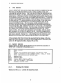
1.
Introduction
GENLPLOT is an interactive program written in FORTRAN and running under
VAX/VMS that enables technicians, scientists, engineers, and other users to
quickly and accurately examine and analyze data. The current version
utilizes the GRAPAC4 plot package1 , reads a standard input file or permits
direct data entry, and is optimized for use with data stored in MDS 2
databases. This program has been the principal interactive data analysis tool
used on the Tara Tandem Mirror Experiment 3 and on the Constance I1 Mirror
Experiment . The program is menu driven with options selected on command
lines distinguished by various prompts. Subsequent changes and additions
to the program will be indicated by a version number greater than that
appearing in the welcome message of the example in section 2.1, and will be
documented in the appropriate menu(s).
2.
Getting Started
The DCL verb GENL is defined; all of its qualifiers and parameters are
optional. Tara defaults appear in parentheses in the following list of qualifiers.
/S=
/D=
/N=
/HCD=
/HCP=
/ALTDB=
Shot number ( -1)
Device type ( RETRO)
Namelist file name ( GENLNML)
{filetype must be NML}
Device type for hardcopy ( QMS)
Port /queue for hardcopy ( P4)
Alternate Data base logical name (TARA$)
The parameter is:
P1
Signal name
The namelist file GENLNML will be used if it exists and no signal name is
given or a logical name translation of the qualifier exists. Otherwise, a prompt
requests a signal name input.
Most directly, GENLPLOT is run by specifying the shot number as a qualifier
and the signal name as a parameter e.g.
$ GENL/S=16140 CCDIAMBS2P
or the default namelist file (see section 3.2.12 entitled Saving the Kit in a
Namelist File) and the current shot number (the default value) may be used. If
no namelist file exists then the user will be prompted for a signal name.
$GENL
Optionally, a shot number qualifier may be specified
1
1
2
GENLPLOT Users Manual
$GENL/S=16140
and/or the device type.
$GENL/S=16140/D=VT125
Other qualifiers specify the hardcopy port/queue, hardcopy device type, the
name of an alternate database, or the name of a namelist file. It should be
remembered that the graphics output can be customized by use of logical
names defined in GRAPAC4. For example, GP4$hcdevtyp, GP4$hcportid,
GP4$devtyp, GP4$hcdevtypCHSC, etc. The definition of any of these logical
names will override the verb defaults.
2
GENLPLOT Users Manual
Sample Session
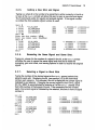
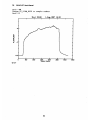
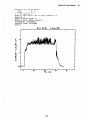
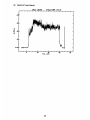
2.1.
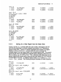
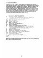
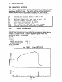
The following sample session illustrates a typical usage of GENLPLOT by
plotting shot 16140, the signal CCDIAMBS2P using the GRAPAC4 MAC
driver which assumes the VersaTerm-PRO 4 Tektronix terminal emulation on
the Apple@ MacintoshTm.
$GENL/S=16140/D=MAC CC_DIAMBS2P
Welcome to GENLPLOT version 2.525
1-Aug-1987 14:10
Shot 16140
I
*
*
I
I
ma
0,
o.a
I
40
D
T Lma.
m=
so
so
Graf> ?
Typing a ? at the
this:
Graf>
COPY
H
LAS
R
V
Make a
Make a
Make a
Replot
Value
Graf>
prompt will bring up the graphic options menu, like
List of additional options:
hardcopy
hardcopy
hardcopy
to the terminal
(of crosshair position in user coordinates
Graf><CR>
This menu allows the user to make a hardcopy of the plot just viewed, replot
the graph to the terminal, or find the value of a specific point on the plot in user
coordinates using a crosshair cursor. Hitting <CR> (carriage return) at the
Graf> prompt will bring up the first page of the main menu. To exit
3
3
4
GENLPLOT Users Manual
GENLPLOT enter EX or EXIT (at any prompt). Note that a response not
recognized at one prompt level is passed up to the next higher prompt level.
GENLPLOT Options:
16140
32 00
CC_DIAMBS2P
A
C
D
Average and variance within a shot ( A#)
CA, CA ##)
Change shot number ( C###, C# ##,
D#)
(
shot)
same
signal,
(new
Dataname
EX
F
G
Exit
Fourier transform ( F#)
Gain and offset (lin, exp, log, or pwr)
J
Join two signals to form a third
K
L
M
Kit of signals ( KS, KS#)
List signals ( LS, LP, LT)
Multi signal plot ( M###)
N
P
R
S
T
V
New shot and signal ( N#)
Plot a signal ( P#, P#/#)
Reread (same signal, same shot) ( R#)
Signal, change parameters of ( S#, SA)
Time axis (abscissa), change parameters of
Voice-print ( V#)
W
World-view, multishot, plot
X
Y
auto/cross correlation ( X#, X#,#)
change "Y" axis (ordinate) parameters
Z
#
Zero, subtract baseline ( Z#)
signal select (# = 1,...,40)
( G#)
( Y###, YA
at any prompt: ? display current menu; CTRL Z terminate input
Genl (Menu page 1/2)><CR>
This menu is the first page (of two) of the main menu; note the current shot
number, signal name, and number of data points of the current signal are
listed on the first line. To see the next page of the main menu the user must
hit the <CR> key. The second page of the main menu follows:
4
GENLPLOT Users Manual
ER
HC
SP
TB
TC
Erase screen
Change the hardcopy port/queue and device type
spawn a process at DCL command level ( DCL, $ verb)
change scale and offset of the "time" base
change "time" base to a different abscissa type ( TS)
CDB
Change data base
DCS
DEV
Define a composit signal
enter new interactive device type
FIT
FIX
Fit a curve (lin, exp, pwr, or nor)
Fix current signal in the kit
OGR
Overall Graph Reduction
PCL
RID
execute PCL
Read In Data
SAV
SUM
Save the kit in a namelist file
average signals over many shots ( SUM###)
WOD
Write Out Data
GLOB
change global settings of CHSC and LCUTLN
( WOD#)
MAIL
execute MAIL
MENU
toggle MENU display off/on
NOTE
use the Notepad
OMIT
change point omission parameter
SMTH
RNML
Geni
( FIT#)
( NOTE msg)
Smooth current signal
Reset the kit from a namelist file
( Menu page 2/2)>EXIT
A carriage return at the Genl ( Menu page 2/2) > prompt will plot the
current signal (autoscaled). Entering the P option at this juncture will perform
the same task at either page of the main menu, although the signal will not
necessarily be autoscaled. Type EXIT or EX to leave GENLPLOT.
5
5
6
GENLPLOT Users Manual
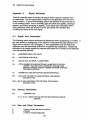
3.
Plot Options
Once in GENLPLOT there are four basic types of options available to the user.
First there are the System Options such as exiting, reading in data, and
changing the hardcopy device. Then there are the Data Set Options such as
listing all the signals in the shot, changing the shot number or selecting a new
signal name. A third type of option is the Display Options which allow the user
to manipulate the plot in such ways as changing axis parameters. The last set
of options are the algorithmic functions which perform various mathematics on
the data such as FFTs, autocorrelations, and curve fitting. In the main menu
all of the options are alphabetized, in the following sections they will be
grouped according to type. The menu gives a brief explanation of each
command, sometimes followed by acceptable formats listed parenthetically.
Three pound signs, ###, indicates that a list (nl-n2,n3,n4-n5...) is acceptable
as input to the indicated command. In a list a range of numbers is indicated
by a hyphen with individual numbers separated by commas, e.g. [1-3,5]
means 1,2,3,5. Two pound signs represent a shot number, and one pound
sign represents the number of a signal in the kit. Note that a response not
recognized at one prompt level is passed up to the next higher prompt level;
also case is ignored. Typing CTRL z (by holding down the control key and
typing Z) will terminate input at any prompt and return to the main menu.
In the examples that follow it should be assumed that the display of the two
page main menu has been "turned off" via the toggling MENU command (see
section 3.1.8 Toggling the Menu Display Off and On).
3.1. System Options
System options are those which allow the user to control the execution of
GENLPLOT in response to the prompt, Genl>.
ER
EX
Erase screen
Exit
HC
SP
DEV
Change the hardcopy port/queue and device type
spawn a process at DCL command level ( DCL, $ verb)
enter new interactive device type
PCL
MAIL
execute PCL
execute MAIL
MENU
toggle MENU display off/on
NOTE
use the Notepad
?
display current menu
3.1.1.
( NOTE msg)
Erasing the Screen
Typing ER at the Genl> prompt will erase the screen.
6
GENLPLOT Users Manual
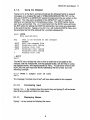
3.1.2.
Exiting GENLPLOT
Typing EX or EXIT at any prompt will terminate the current GENLPLOT
session. The following example demonstrates how statistics, including
elapsed actual and CPU time of the GENLPLOT session being exited are
displayed.
Genl> EX
ELAPSED:0 00:01:09.66
CPU:
0:00:04.77
BUFIO:
68
DIRIO:
57
FAULTS:
681
$
3.1.3.
Changing the Hardcopy Queue and the Device Type
Typing HC at the Genl> prompt enables the user to change the current
hardcopy queue and device type. In order to switch to a printer other than the
default printer the user must know the name of the print queue and the type of
printing device located at that queue. In this example P8 is the name of the
new print queue and QMSIGV is the type of printing device.
Genl> HC
Enter HCPORTID> P8
Enter HCDEVTYP> QMSIGV
Genl>
3.1.4.
Spawning a Process at DCL Command Level
To spawn a subprocess at the DCL command level from inside of a
GENLPLOT session the user can type sp and execute as many DCL
commands as desired before logging back out as in this example
Genl> SP
$ SHOW TIME
8-JUN-1987 13:25:19
$ LOGOUT
Genl>
Or a DCL command preceded by a $ may by entered on one line as in the
following example, after which control is automatically returned to the
GENLPLOT level.
Genl>
$
DIR
TARA$ROOT: [AML]
Directory TARA$ROOT: [AML]
ALLLIB.OLB;1
GP4.OLB;1
TPUSECINI.200;4
VECSHR.EXE; 2
AUTL.OLB;9
TAP.OLB;2
TPUSECINI.VT100;1
BEV.OLB;2
TAPSHR.EXE;15
TPUSECINI.VT200;1
Total of 13 files.
Genl>
7
GLSUB.OLB; 1
TPU.VT200KEYS;3
UCB.OLB;1
7
8
GENLPLOT Users Manual
Similarly, the command
to GENLPLOT.
DCL
prompts for one DCL command and then returns
Genl> DCL
DCL Command> SHOW LOGICAL AML$
"AML$" = "TARA$ROOT:[AML] " (LNM$SYSTEM TABLE)
Genl>
3.1.5.
Changing the Terminal Device Type
If the /D qualifier was not used to initiate GENLPLOT (see section 2. Getting
Started) or was used in error so that the terminal device type is different from
the terminal being used, then the user has the ability to change the terminal
device type using the DEV command. The following example illustrates how to
change to the G0235 device type which corresponds to GraphOn model 235
terminals.
Genl> DEV
Enter DEVTYP> G0235
Genl>
3.1.6.
Executing PCIL
Typing PCL at the Genl> prompt gives the user access to PCL, the plot control facility
of MDS
3.1.7.
Execute VMS Mail
Typing MAIL at the Genl> prompt allows the user to use the VMS Mail facility
without exiting the GENLPLOT session.
Genl>
MAIL
MAIL> EXIT
Genl>
3.1.8.
Toggling the Main Menu Display Off and On
The MENU command gives the user the option of toggling on or off the display
of the two page main menu. Note that there is no response from GENLPLOT
for the MENU command. For all of the examples demonstrated in this manual
the menu display has been toggled off.
8
GENLPLOT Users Manual
3.1.9.
Using the Notepad
Typing NOTE at the Genl> prompt will activate the Notepad facility to append
messages on a notepad file kept in SYS$LOGIN:GENLNOTES.TXT; on the
first use of NOTE in a GENLPLOT session the date and time are written on the
notepad. The note pad is available to the GENLPLOT user for making or
adding to an ongoing file of miscellaneous notes. The NOTE facility has its
own menu and prompt. The .EDIT command from the NOTE menu will bring
the EDT editor for editing the NOTE file (remember new notes are appended
to the end of the file). Typing NOTE and <CR> will invoke the NOTE menu as in
this example the first time and just the > prompt subsequently.
Genl> NOTE
Note pad options:
msg
Text to be entered on the notepad
except
.EDIT
.EXIT
.HELP
.QUIT
.
EDIT the notepad file
Terminate note taking
Display this list
Terminate note taking
Terminate note taking
Display this list
>.QUIT
Genl>
The NOTE menu directs the user on how to enter text to be added to the
notepad, edit the notepad file, exit the notepad facility, ask for help on using
the notepad facility, and display the NOTE menu. To add a line of text to the
NOTE file, the user may enter NOTE followed by the line of text as in the
following example.
Genl> NOTE a simple
Genl>
line
of
text
The message "a simple line of text" will have been added to the notepad.
3.1.10.
Terminating Input
Typing CTRL z (by holding down the control key and typing Z) will terminate
input at any prompt and return to main menu.
3.1.11.
Displaying Menus
Typing ? at any prompt will display that menu
9
9
10
GENLPLOT Users Manual
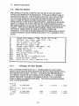
3.2.
Data Set Options
After plotting an initial set of data the user may want to see more without
having to quit GENLPLOT and starting over. There are six different ways of
accessing new data sets. In the first page of the main menu there are three.
The user could change the shot number and keep the signal the same (C
option), change the signal and keep the same shot number (D option), or
change the shot number and the signal (N option). Assembling a set of data
signals or 'building a kit' is done most often by using the Dataname option.
After adding signals or at any time the user may display all the signals with the
kit option. There are four different types of signals, regular, fixed, composit,
and arrayed. Signal names are made up of letters, numbers and
underscores. In the case of arrayed signals part of the signal name is a list of
numbers enclosed in square brackets (see section 3. for a description of list
format).
C
D
K
L
N
R
CDB
DCS
FIX
RID
SAV
WOD
RNML
3.2.1.
Change shot number ( C###, C# ##,
Dataname (new signal, same shot)
Kit of signals ( KS, KS#)
List signals
CA, CA # #)
D#)
( LS, LP, LT)
New shot and signal ( N#)
Reread (same signal, same shot) ( R#)
signal select (# = 1,...,40)
Change data base
Define a composit signal
Fix current signal in the kit
Read In Dat.a
Save the kit in a namelist file
Write Out Data
( WOD#)
Reset the kit from a namelist file
Changing the Shot Number
The C command, entered at the Genl> prompt enables the user to add a
signal to the kit using the same signal the one that is currently selected, from a
user-specified shot number. The c### command,where ### represents a
list of signals, changes the shot number of a list of signals, c# ## changes a
specific signal and CA changes all the signals in the kit. The C command
works on regular and arrayed signal types. The following example illustrates
some of these possibilities.
Genl> K
1 16140
CCDIAMBS2P
Genl> C
Enter new shot number: 16141
Genl> K
1 16140
CCDIAMBS2P
2 16141
*CCDIAMBS2P
Genl>
10
3200
-0.100000
1.10000
3200
3200
-0.100000
-0.100000
1.10000
1.10000
GENLPLOT Users Manual
Genl> K
1 16140
2 16141
3 16142
11
3200
4001
8000
-0.100000
-0.100000
-0.100000
1.10000
-0.100000
-0.100000
Genl> C1-3
Enter new shot number: 16143
CCDIAMBS2P
CCNL_BS2P
CC PPD 4
Genl> K
1 16143
CCDIAMBS2P
CCNLBS2P
2 16143
3 16143
*CCPPD_4
3200
4001
8000
-0.100000
-0.100000
-0.100000
1.10000
-0.100000
-0.100000
Genl> CI
Genl> K
1 16144
2 16143
3 16143
3200
4001
8000
-0.100000
-0.100000
-0.100000
1.10000
-0.100000
-0.100000
3200
4001
8000
-0.100000
-0.100000
-0.100000
1.10000
-0.100000
-0.100000
CCDIAMBS2P
CCNL_BS2P
*CCPPD_4
16144
*CCDIAMBS2P
CCNL_BS2P
CCPPD_4
Genl> CA 16146
CCDIAMBS2P
CCNL_BS2P
CCPPD_4
Genl> K
1 16146
*CCDIAMBS2P
2 16146
CCNL_BS2P
3 16146
CCPPD_4
Genl>
3.2.2.
Asking for a New Signal from the Same Shot
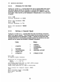
Typing D at the Genl> prompt allows the user to add a new signal to the kit
from the shot data that is currently selected (see section 3.2.7 Selecting a
signal to work with). Typing D#, where # represents the number of a signal
already in the kit, at the Genl> prompt allows the user to change the
indicated signal to a new signal name or an arrayed signal name. An arrayed
signal may be read in by entering an arrayed signal: string[list], where list is a
list of numbers, e.g. CC PPD_[1 -4,7]. The D command also allows the user to
delete a signal from the kit even if they are fixed (see section 3.2.10 Fixing the
Current Signal in the Kit). To delete a signal, enter a <CR> at the Enter new
signal name: prompt. The following example illustrates all three situations.
Genl> K
1 16140
CCDIAMBS2P
Genl> D
Enter new signal name: CCPPD_4
Genl> K
CCDIAMBS2P
1 16140
2 16140
*CCPPD_4
Genl> D1
Enter new signal name: CCNLBS2P
3200
-0.100000
1.10000
3200
8000
-0.100000
1.10000
4001
8000
-0.100000
0.OOOOOOE+00 0.OOOOOOE+00
Genl> K
1 16140
2 16140
*CCNL_BS2P
*CCPPD_4
11
-0.100000
0.OOOOOOE+00 0.OOOOOOE+00
GENLPLOT User's Manual
12
Genl>
D2
Enter ne w signal name:<CR>
Genl> K
4001
*CCNLBS2P
1 16140
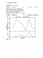
Genl> D
Enter new signal name: CCPPD_[1-8]
Enter name for abscissa variable><CR>
Enter abscissa values (later)? [y/N]><CR>
Enter start time and delta> 0,80,1
Zero each signal? [y/N]><CR>
Gain and offset for each signal? [y/N]><CR>
Genl> K
3200
CCDIAMBS2P
1 16140
8
S&V
A *CCPPD_[1-8]
2 16140
Genl> P
2
0
Shot 16140
I
-0.100000
-0.100000
-0.100000
1.10000
0.OOOOOOE+00 0.OOOOOOE+00 N
1-Rug-3987 14:10
i
i
Aa
C
a
.20
L
D. Oat-
.A4
U
0
a
p
.A2
p
a
2
4
Soap 14 Nawbor
Graf> <CR>
Genl>
12
6
0
GENLPLOT Users Manual
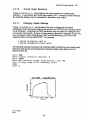
3.2.3.
13
Listing the Contents of the Kit
Typing K at the Genl> prompt will generate a list of the contents of the kit. The
GENLPLOT kit is the set of different shots and their different signals that have
been opened for display and numerical manipulation in the current
GENLPLOT session. Listing the contents of the kit shows what has been
opened so far. The information displayed by the kit listing includes the
following: first is the signal number which is used for selecting a signal to
work with (see section 3.2.7); next is the shot number for the signal; then the
signal title; followed by the number of data points in the signal; and finally the
signal axis interval parameters (if these two numbers are equal autoscaling is
used).
1
CC_DIAMBS2P
CC_DIAM_BS2P
CC_NLBS2P
1+3
16140
2 16141
3 16140
4 16140
5 16141
Genl>
3200
3200
F
C
A *CCPPD_[1-8]
4001
3200
8
T1
S&V
-0.100000
1.10000
-0.150000
-0.150000
0.OOOOOOE+00 0.OOOOOOE+00
-1.OOOOOOE+13 1.100000E+14
0.OOOOOOE+00 0.OOOOOOE+00 N
T2
1
Additional parameters may appear at three places 1,2,3 indicating at 1 signal
types, F for fixed, C for composit , A for arrayed signals and no parameter
indicates a regular signal (see section 3.2 for a description of signal types). At
2 signal plot class: blank, signal; S&V, signal and variance; HS,
histogrammed signal; and HS&V, histogrammed signal with variance. And at
3 abscissa type: blank, time; N, sample number; F, frequency; S, shot
number; 0, other. In order to display a more detailed list of parameters for a
signal the user can use the KS or KS# command which produce a listing like
the following.
Genl> KS 1
Signal parameters: Current signal number
Signal:
vs.:
1
Shot 16140
1-Aug-1987 14:10
CCDIAMBS2P
Time, msec
CC DIAM BS2P
CCDIAMBS2PTM
Number of sample points is
Sample point increment is
3200
1
Time, msec axis parameters:
WA
WB
-5.00
95.0
IW NW LW
0
4
5
Signal axis parameters:
SA
SB
IS NS LS
-0.100
Genl>
1.10
0
4
3
WFT
DWLT
-20.0
20.0
SFT
DSLT
-0.400
0.400
WSC
WREF
1.OE-03
0.OE+00
The signal and time axis parameters that appear in this listing are described
in appendices A.1 and B.1 respectively.
13
14
GENLPLOT User's Manual
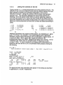
3.2.4.
Listing the Signals in the Shot
Typing L at the Genl> prompt will bring up the
TDB command>
prompt and
hitting carriage return will produce a list of all the signals available for the
current shot number. Typing LS at the Genl> prompt will list all the raw data
signals, LP will list the processed data signals, and LT Will list all the
transforms. Wild card characters in a search list are also possible, e.g.
Genl> L
TDB Command> DIR
Directory of shot
*CC PPD_*
16141
LEVEL: T Transforms
CCPPD_1_B
CCPPD 4 B
CCPPD_7_B
CCPPD_I_1_TM
CCPPD_I_3
CCPPD_I_4_TM
CC PPDI_6
CCPPDI_7 TM
CCPPDN1
CCPPDN_2_TM
CCPPD_N_4
CCPPD_N_5_TM
CCPPD_N_7
CCPPD_N_8_TM
Total of 40 records
LEVEL: S Raw Data
CC PPD_1
CCPPD_2_TM
CC_PPD_4
CCPPD_5_TM
CCPPD_7
CCPPD_8 TM
Total of 16 records
Grand Total of 56 records
Genl>
CCPPD_2_B
CC_PPD_5_B
CC_PPD_8_B
CCPPD_I_2
CCPPD_I_3_TM
CC PPD I 5
CCPPDI_6_TM
CCPPD_I_8
CCPPDN_1 TM
CCPPDN_3
CC_PPD_N_4_TM
CCPPD_N_6
CCPPD_N_7_TM
CCPPD_3_B
CC_PPD_6_B
CC_PPD_I_1
CCPPD_I_2_TM
CCPPD_I_4
CCPPDI_5 TM
CC_PPDI77
CC PPD I 8 TM
CCPPDN_2
CC_PPD_N_3_TM
CCPPD_N_5
CCPPD_N_6_TM
CC_PPD_N_8
CCPPD_1_TM
CCPPD_3
CCPPD_4_TM
CC_PPD_6
CC_PPD_7_TM
CC PPD 2
CCPPD_3_TM
CCPPD_5
CCPPD_6_TM
CC_PPD_8
See the TDB directory command in MDS; in fact any TDB command may be
executed.
14
GENLPLOT User's Manual
3.2.5.
15
Getting a New Shot and Signal
Typing N#, where # is the number of a signal that is either currently in the kit or
is new, at the Genl> prompt will allow the user to open a new shot and signal.
The N command works for regular and arrayed signals. If the signal number
is omitted the first available signal number is used.
Genl> K
*CCNLBS2P
1 16140
2 16141
CCDIAMBS2P
3 16142
CCDIAMBS2P
4 16143
CCDIAMBS2P
Genl> N5
Enter new shot number: 16144
Enter new signal name: CCPPD_4
Genl> K
1 16140
2
3
4
5
16141
16142
16143
16144
4001
3200
3200
3200
-1.OOOOOOE+13
-0.100000
-0.100000
-0.100000
4001
3200
3200
3200
8000
CCNLBS2P
CCDIAMBS2P
CCDIAMBS2P
CCDIAMBS2P
*CCPPD_4
1.100000E+14
-0.100000
-0.100000
-0.100000
-1.OOOOOOE+13 1.100000E+14
-0.100000
-0.100000
-0.100000
-0.100000
-0.100000
-0.100000
0.OOOOOOE+00 0.OOOOOOE+00
Genl>
3.2.6.
Rereading the Same Signal and Same Shot.
Typing R#, where # is the number of a signal in the kit, at the Genl> prompt
will allow the user to reread the same signal and shot and to reset the
averaging, gain and offset, and zeroing options in order to recover the original
signal.
3.2.7.
Selecting a Signal to Work With
Typing the number of the desired signal at the Genl> prompt selects that
signal to work with. Displaying the kit (see section 3.2.3) will show what
number each signal is. For example if the kit is displayed the current signal is
indicated by an asterisk. Changing the current signal to shot 16142, signal
CCNLBS2P is accomplished by entering a 3 at the Genl> prompt since
that is the number of that signal in the kit. If the contents of the kit is listed
again, the current signal is indicated by the asterisk, this time in front of signal
number 3.
Genl>
K
1 16140
2 16141
3 16142
4 16143
Geni> 3
Geni> K
1 16140
2 16141
3 16142
4 16143
CCDIAMBS2P
CCDIAMBS2P
3200
*CCPPD_4
3200
4001
8000
CCDIAMBS2P
CC DIAM BS2P
*CCNL BS2P
CCPPD_4
3200
3200
4001
8000
CCNL_BS2P
Genl>
15
-0.100000
-0.100000
1.10000
1.10000
0.OOOOOOE+00 0.OOOOOOE+00
0.000000E+00 0.000 OE+00
-0.100000
-0.100000
1.10000
1.10000
0.OOOOOOE+00 0.OOOOOOE+00
0.OOOOOOE+00 0.OOOOOOE+00
16
GENLPLOT User's Manual
Changing the Data Base
3.2.8.
Typing CDB at the Genl> prompt allows the user to change MDS data bases
and access signals stored, for example, in a private MDS database. In the
following example the current database is changed from TARA$ to TS$ and
back again. Note how the current database is indicated after a CDB command
is issued.
Genl>
CDB
Current database is TARA$
Enter new database> TS$
Genl> CDB
Current database is TS$
Enter new database> TARA$
Genl>
Defining a Composit Signal
3.2.9.
Typing a DCS at the Genl> prompt allows the user to construct a composit
signal from regular signals. The following table lists the possible unary and
binary operations and a description of each. It should be noted that when
entering formulas for constructing composit signals the operations are case
specific and no spaces are allowed in between characters.
Unary
Binary
+
/
d
=addition
=subtraction
=multiplication
=division
=derivative, dsl/ds2
S
=integral, Js1ds2
=negation
/
d
r
s
=inversion
="time"derivative
=square root
=integration
Genl> DCS
In Composit Signal Formulae:
Operations for joining signals:
Unary :
Binary:
+ -
*
/ d r S
/ d
S
Scan binary operations left to right within groups
Groups defined by balanced ()s
Single unary operation on right in each group
Enter
1*2+3
Enter
Enter
Genl>
formula for composit signal: 1*2+3
alternate signal title><CR>
panel text><CR>
P
16
GENLPLOT User's Manual
Shot 16140
-2 -
*
*
I-Sug-1987
**
'5a
-. 4
U.'
4.
(~.J
4
D
3.2.10.
40
TLNA,
3
60
so
Fixing the Current Signal in the Kit
Typing FIX at the Genl> prompt allows the user to fix the current signal in the
kit, that is to make the signal permanent and unaffected by change
commands. A fixed signal may only be deleted by the D option (see section
3.2.2 Asking for a New Signal from the Same Shot).
17
17
GENLPLOT User's Manual
18
3.2.11.
Reading in Data
Typing RID at the Genl> prompt allows the user to read in data. This function
is used to read any file created by the WOD command (in section 3.2.13 Writing
Out Data) , or by another program in the correct format (see below), or to allow
direct data entry by the user. The following example demonstrates both
possibilities.
Genl> RID
Enter data set filename or <CR> for direct data entry> QUICK.WOD
Genl>
Genl> RID
Enter data set filename or <CR> for direct data entry><CR>
How many data points? > 10
Signal Title
> Y AXIS
Abscissa Title > X AXIS
with variances? [y/N]><CR>
Abscissa/ordinate pair ( 1)
Abscissa/ordinate pair ( 2)
Abscissa/ordinate pair ( 3)
Abscissa/ordinate pair (
4)
Abscissa/ordinate pair ( 5)
Abscissa/ordinate pair ( 6)
Abscissa/ordinate pair ( 7)
Abscissa/ordinate pair (
8)
Abscissa/ordinate pair (
9)
Abscissa/ordinate pair ( 10)
>
>
>
>
>
>
>
>
>
>
1,3.1
2,4.5
3,1.25
4,9.0
5,8.3
6,5.7
7,1.8
8,3.5
9,7.2
10,2.4
Genl> P
9
7-
'-4
a
4
X RXIS
Graf>
Genl>
18
B
12
GENLPLOT Users Manual
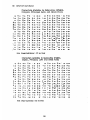
19
The following is a listing of quick.wod file illustrating the file format required by the
RID command. The first seven lines are optional. The KST parameter (signal plot
class) is described in appendix A.6. The data lines are abscissa value, ordinate
(signal) value, and optionally the variance of the ordinate.
$ type
quick.wod
AXTXT
PNTXT
DATESTR Shot 16140
SIGTITL CCDIAMBS2P
TTITL Time, msec
1-Aug-1987 14:10
41
NPTS
KST
0
5.0000
5.0250
5.0500
5.0750
5.1000
,
0.47506
,
,
0.47499
0.47492
0.47685
,
0.47878
5.1250
,
5.1500
5.1750
5.2000
5.2250
5.2500
5.2750
5.3000
5.3250
5.3500
5.3750
5.4000
5.4250
5.4500
5.4750
,
,
0.47871
0.47864
0.47857
0.47850
0.48043
0.48236
0.48429
,
0.48222
,
5.5000
,
0.48415
0.48408
0.48601
0.48594
0.48387
0.48380
0.48373
0.48566
5.5250
5.5500
5.5750
,
,
5.6000
5.6250
,
,
0.48946
0.49139
0.49132
5.6500
5.6750
5.7000
5.7250
5.7500
5.7750
,
0.49325
,
,
0.49518
0.49711
,
0.49904
,
5.8000
,
5.8250
,
5.8500
,
5.8750
,
5.9000
,
0.49897
0.49890
0.49883
0.50476
0.50469
0.50462
0.50455
5.9250
,
0.50648
5.9500
,
0.50641
5.9750
6.0000
,
0.50634
0.50627
,
,
,
,
,
,
,
,
,
,
,
,
,
,
0.48559
0.48752
19
GENLPLOT User's Manual
20
Saving the Kit in a Namelist File
3.2.12.
Typing SAv at the Genl> prompt allows the user to save the kit in a namelist
file to easily recreate the GENLPLOT run later on. The '.NML' is not required
when naming the file since it is the default. A <CR> will use the default name
GENLNML.NML.
Genl> SAV
Enter name of namelist save file> SAV.NML
Genl>
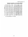
Writing Out Data
3.2.13.
Typing WOD at the Genl> prompt allows the user to write out data to the screen
and/or to a file. Data saved in a file can later be read in using the RID
command described in section 3.2.10 Reading in data. Typing a ? at the WOD>
prompt will display the WOD menu which allows the user to reenter time and
array bounds, write output to a file, continue printing the data on the screen, or
quit WOD. The data are displayed a screen full at a time.
Genl> WOD
3200
1 16140 CCDIAMBS2P
Enter time bounds (and skip increment): Ts,Te[,iskp]> 5,10
400
5.0000
0.47506
401
5.0250
0.47499
402
5.0500
0.47492
403
5.0750
0.47685
404
5.1000
0.47878
405
5.1250
0.47871
406
5.1500
0.47864
407
5.1750
0.47857
408
409
410
5.2000
5.2250
5.2500
0.47850
0.48043
0.48236
411
412
413
5.2750
5.3000
5.3250
0.48429
0.48222
0.48415
414
5.3500
0.48408
415
5.3750
0.48601
416
5.4000
0.48594
417
5.4250
0.48387
418
5.4500
0.48380
419
5.4750
0.48373
420
421
422
5.5000
5.5250
5.5500
0.48566
0.48559
0.48752
WOD> ?
WOD>
Q
R
W
<CR>
List of additional options:
Quit
Reenter time/array bounds
Write output to a file (QUICK.WOD)
(this file may be reread by using RID)
continue printing
WOD> W
20
GENLPLOT Users Manual
Enter file name
21
(default QUICK.WOD)><CR>
WOD><CR>
Genl>
This example will display the data between 5 and 10 msec; if a <CR> is typed
for time limits, array bounds are asked for and if none entered the entire signal
is displayed.
3.2.14.
Resetting the Kit from a Namelist File
Typing RNML at the Genl> prompt allows the user to reset the kit from a
namelist file (like that created previously using SAV). Any existing kit is
replaced since this is not an additive process. To save a kit in a namelist file
refer to section 3.2.12 Saving the kit in a namelist file. The default file type is
'.NML' and does not necessarily have to be included in the filename.
Genl> RNML
Enter namelist filename> SAV.NML
Genl>
21
22
3.3.
GENLPLOT Users Manual
Display Options
There are several alternatives to plotting a signal versus time. For example a
multisignal plot will display any number of signals at a time just as a Worldview plot will display several shots at a time. Also available to the user is
voice-print plotting and the ability to set gain and offset or change axis
parameters.
M
P
S
T
V
W
Y
TB
TC
OGR
GLOB
OMIT
SMTH
Multi signal plot ( M###)
Plot a signal ( P#, P#/#)
Signal axis, change parameters of ( S#, SA)
Time axis (abscissa), change parameters of
Voice-print ( V#)
World-view, multishot, plot
change "Y" axis (ordinate) parameters ( Y###, YA ###)
change scale and offset of the "time" base
change "time" base to a different type ( TS)
Overall Graph Reduction
change global settings of CHSC and LCUTLN
change point omission parameter
Smooth current signal
22
GENLPLOT User's Manual
3.3.1.
23
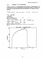
Multi Signal Plot
The user may want to plot several signals in the kit all on one plot. The multisignal plot facility is available for this purpose. The M command will display all
current signals in the kit numbered in the order in which they were opened.
The user must then indicate which signals are to appear on the plot using
their signal number. Alternatively, the user may simply enter the command
M###, where ### represents a list of signals (see section 3.1 Plot Options).
After the plot is displayed the Mcommand brings up its own menu allowing the
user to make a hardcopy of the plot, replot it to the terminal, rotate the plot,
and quit the M menu.
Genl> N
1 16140
2 16140
3 16140
CCDIAM_BS2P
CCNL_BS2P
CCPPD_4
0.000000E+00 0.000000E+00
0.000000E+00 0.000000E+00
0.000000E+00 0.000000E+00
3200
4001
8000
Enter list of signal numbers> 1,2,3
Shot 16140
1-Aug-1987 14;10
94
13
1I
D
I
20
40
TLimes.
M>
List of additional options:
COPY Make a hardcopy
H
Make a hardcopy
LAS
Make a hardcopy
Quit this menu
Q
R
Replot to the terminal
ROT
Negate graph rotation flag
M><CR>
Genl>
23
60
I
a
I
80
I
24
GENLPLOT User's Manual
3.3.2.
Plot a Signal
To plot the current signal, enter P as in the sample session in section 2.1. P# can
also be used to plot a specific signal. To plot one signal against another use the
command P#/# where each # stands for a different signal number. In the following
example the user has plotted signal 1 against signal 2.
Genl> K
1 16140
2 16141
3200
8000
CCDIAMBS2P
*CCPPD_4
-0.100000
Genl> P1/2
Enter Y to connect points><CR>
Shot 1614L
1-Rug-1987 14:28
I
6
£
&*
A&i~
.8
I
&
&
&S
~
a
£
AA
&
*I
AL
£
£
A
a
*~
o.a
-
-. 072
3raf>
Genl>
A
Am
h
'0 6&
i
&
ha
a
A%
A&
A
I
I
i
-. 070
-.060
-.006
Start tine and werjilag interval
24
1.10000
0.OOOOOOE+00 0.OOOOOOE+00
-S.0
0.39[S
GENLPLOT User's Manual
25
Signal Axis
3.3.3.
Typing s at the Genl> prompt allows the user to change all of the signal axis
parameters. See appendix A.1 Signal Axis Parameters and appendix B.1
Abscissa Axis Parameters for a description of each of the axis parameters.
See appendix C. Making a Text String in GP4 for a description on how to
construct text strings for such things as the signal and abscissa titles.
Genl> S
Signal parameters: Current signal number
Signal:
CCDIAMBS2P
vs.:
1
Shot 16140
1-Aug-1987 14:10
Time, msec
CCDIAMBS2P
CC_DIAMBS2PTM
Number of sample points is
Sample point increment is
Time, msec axis parameters:
WA
WB
IW NW LW
95.0
-5.00
0
4
5
3200
1
WFT
DWLT
-20.0
20.0
Signal axis parameters:
IS NS LS
SA
SB
1.10
-0.100
0
4
3
SFT
DSLT
-0.400
0.400
Automatic autoscale [y/N]><CR>
Enter axis parameters: SA,SB,IS,NS,LS[,sft,dslt]>
Enter sample increment> 1
CCDIAMBS2P
Alternate signal title><CR>
Alternate panel title><CR>
WSC
WREF
1.OE-03
0.0,0.9,0,9,3
Time, msec
Alternate abscissa title><CR>
1-Aug-1987 14:10
Shot 16140
Alternate graph title><CR>
Genl> P
1-Aug-1987 14:10
Shot 16140
D
20
40
Trine,
Graf>.<CR>
Genl>
25
r.o
60
0.OE+00
60
26
GENLPLOT User's Manual
3.3.4.
Time (Abscissa) Axis
Typing T at the Genl> prompt allows the user to change all the time (abscissa)
axis parameters. See appendix B.1 Abscissa Axis Parameters, for a
description of each of the parameters prompted for by the T command.
Genl> T
Change
Time, msec
TA
-5.00
TB
95.0
0
Enter axis parameters:
Genl> P
4
5
DTLT
TFT
IT NT LT
20.0
-20.0
TA,TB,IT,NT,LT[,tft,dtlt]>
Shot 16140
0.0,65.0,0,4,5,-20. ,20.
1-Aug-1987 14: 10
I
*
I
I
.
.
*
~
.81
0,
.41
0.A
I
a
I
2,
TrLua,
26
I
I
40
.
I
I
so
27
GENLPLOT Users Manual
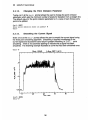
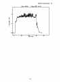
Voice Print
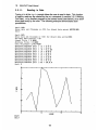
3.3.5.
Typing v at the Genl> prompt allows the user to generate a voice print plot of
a signal; a contour plot of time lapsed FFT's. After the voice print is plotted a
menu is displayed allowing the user to change the Average FFT axis
parameters, modify contour levels, make a hardcopy, quit the voice print
facility, replot to the terminal, change the signal and time axis , and toggle the
between the time and frequency displays.
Non-kit signal? [y/N]><CR>
Enter number of points per FFT
[<CR> = 256]
i.e. 32,64,128,256,512,1024,2048,4096,or 8192 ><CR>
Enter how many times to smooth [<CR> = 0]><CR>
Enter number of first isopleth [<CR> = 5]<CR>
7 8 9
6
5
4
3
2
1
.0001, .0003, .001, .003, .01, .03, .1,.3, .8><CR>
1-Aug-1987 14:10
Shot 16140
U-
104 r
Ga
60
2
4a
I-
213
a
a
*I
I
*
I
I
,
A
CL
change Average FFT axis
modify Contour Levels
COPY
make a hardCOPY
change Frequency axis
make a Hardcopy
make a hardcopy
Quit
Replot to the terminal
change Signal axis
change Time axis
Toggle Time-Frequency displays
Q
R
S
T
TTF
,
,
a
Frqumnyp Hiz
2GS varplee
Trnaora af
List of interactive options:
F
H
LAS
I
III
V>TTF
27
20
G
GENLPLOT User's Manual
28
--
I
AA.
1-Aug-1987 14, 10
Shot 16140
.31
I
I
I
i
jZZ~z~
0
S10
U
L
U-
D
V>
40
T im,
TransPrm .P
Genl>
28
m o
256
60
IGnpOes
80
GENLPLOT Users Manual
29
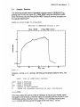
World-view
3.3.6.
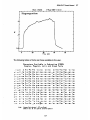
Typing a w at the Genl> prompt allows the user to create a multi-shot plot, to survey
or to scan data over many shots possibly plotting one against another and to select
among display options as the signal is plotted. Note that in world-view if fluctuation
amplitude is selected to start then there is an additional option to suppress baseline
trends from the variance estimates.
Genl> W
1 16140
1.10000
-0.100000
3200
*CCDIAMBS2P
WORLD parameters
Enter signal number for ordinate> 1
Enter time bounds for averaging ordinate> 24,40
Signal display flag:
Average
<CR> or 0
T
or 1
Fluctuation Amplitude
S
or 2
Standard Deviation
Enter flag><CR>
Enter signal number for abscissa or return to use shot number><CR>
Enter list
of shot numbers> 16140-16145,16147,16148-16149
Enter Z to input abscissa value for each shot><CR>
Start shot 16140
Start shot 16141
Start shot 16142
Start shot 16143
Start shot 16144
Start shot 16145
Start shot 16147
Start shot 16148
Start shot 16149
Survey Pot
d-
o.0 S
1 140
.
S
I
*
16L44
Tim
,
.
I
.
16146
Shot rmborounda.
24.000
29
*
I
.
16152
40.UUD
.
*
.
161ES
30
GENLPLOT User's Manual
Typing a ? or a <CR> at the w> prompt after the plot has been drawn will bring up a
menu instructing the user on how to perform various manipulations on the world plot.
For example the abscissa parameters can be changed, shots can be added to the
data set, error bars can be toggled on and off. The user can make a hardcopy,
change the title of the graph, initialize parameters, negate shot numbering on each
point, change the ordinate axis parameters, replot the graph to the terminal, reread
the data, enter a new list of shot numbers, store results as a signal in the kit, swap
signals, display a table of parameters and write output to a quick.dmp file (not
compatible with RID format described in section 3.2.11).
W>
A
List of additional options:
Abscissa, change parameters of
( new data: AD; display flag: AF; time bounds: AT;
axis parameters: AS; new title: ATIT)
ASHT
Add SHoT numbers to current list
B
COPY
Bars, choose error bars or not
Make a hardcopy
GTIT
Change graph title
H
I
Make a hardcopy
Initialize (all parameters)
LAS
Make a hardcopy
N
0
Negate shot numbering on each point
Ordinate, change parameters of ( OD, OF, OT, OS)
( new data: OD; display flag: OF; time bounds: OT;
axis parameters: OS; new title: OTIT)
Q
Quit this menu
R
Replot to the terminal
RD
S
Reread the data from all the shots
Shot numbers, new list of (and make plot)
STOR
SWAP
T
Store results as a signal
Interchange signals
Table of parameters, display
W
Write output to a file
(QUICK.DMP)
W><CR>
Genl>
At this point if worldplot is reentered the data are still there and may be replotted with
the R option or otherwise manipulated.
30
GENLPLOT User's Manual
31
Changing "Y" Axis Parameters
3.3.7.
Typing a y at the Genl> prompt allows the user to change "Y" axis parameters. The
Y command is similar to but abbreviated S command (see section 3.3.4 Signal Axis).
A list of all of the signal parameters and their descriptions is in Appendix A Signal
Attributes.
Genl> Y
Signal parameters:
Current signal number
2
Shot 16140
1-Aug-1987 14:10
CCDIAMBS2P
Signal:
Time, msec
vs.:
CC DIAM BS2P
CC DIAM BS2P TM
3200
Number of sample points is
Sample point increment is
Time, msec axis parameters:
IW NW LW
WB
WA
0 4 5
95.0
-5.00
Signal axis parameters:
IS NS LS
SB
SA
0 4 3
-0.100
-0.100
1
DWLT
WFT
-20.0
20.0
SFT
-0.400
DSLT
0.400
Automatic autoscale [yIN]> <CR>
Enter axis parameters: SA,SB,IS,NS,LS[,sft,dslt]>
WSC
WREF
0.OE+00
1.OE-03
0.0,0.9,0,4,3,0,0
Genl> p
.~
Shot 16140
[U
1-Aug-1987 14:10
I
I
I
0)
I
I
D
I
40
Tit, n
31
60
I
so
I
I
32
GENLPLOT Users Manual
Changing Scale and Offset of the "Time" Base
3.3.8.
Typing a TB at the Genl> prompt allows the user to change the scale and offset of
the time base. So if, for example, the user wishes to change the time axis to be in
seconds instead of milliseconds the offset would be zero and the scale would be
1000.
Genl> TB
Choose abscissa type
1 Time, msec
2 Sample Number
3 Frequency, kHz
4 Shot Number
5 Special
Choice = 1
Time, msec
Change
Enter scale and reference (scaled)> 1000,0
New abscissa label> Time in seconds
Genl> P
1-Rug-1987 14; 10I
Shot 16140
I
I
I
I..............I
-1----
I
I
I
I
.4
0.A
-
I
0. DM
I
I
-
.
.
I
.
.
I
.
S
.040
TLN4
in soooCio
.060
S
.
.
UUU
.000
Gra f>
CAUTION: A value of one thousand works immediately but will be wrong when
new signals are read in since time data is stored in seconds. A more correct way of
changing from msec to seconds would be to use a scale of 1 and then reread in the
signal.
32
GENLPLOT Users Manual
3.3.9.
33
Changing the "Time" Base to a Different Type
Typing TC at the Genl> prompt allows the user to change the time base to a different
type. TC changes the "time" base to sample number by default. To change it to
another type, like frequency for example, the TC command must be issued again
whereupon a menu will prompt for the desired type. The TS command does the
same thing.
Genl> TC
Change CCDIAMBS2P to sample number
Genl> TC
Transform sample number to ?
1 Time, msec
2 Sample Number
3 Frequency, kHz
4 Shot Number
5 Special
Choice = 3
Change to Frequency, kHz
Enter parameters DEL, AO for
Genl> P
A = DEL*n + AO > 1.0,0
Shot 16140
i
i
1-Aug-1987 14:10
i
i
i
iI
iI
2000
II
-a
I
.4
o.0
a
Ii
5DO
Ii
1LDO
15[I
Fr.quen*6,
Graf>
33
Idiz
3000
3600
34
GENLPLOT User's Manual
Genl> TS
Change CCDIAMBS2P to sample number
Genl> P
Shot 16140
I
I
i
I
1-Aug-1987 14; 10
I
I
I
I
H
I
.4'
0.0
a
SLD
I
I
153D
Saupl
Graf>
34
2000
Numbr
a
I
300
300
GENLPLOT User's Manual
3.3.10.
35
Overall Graph Reduction
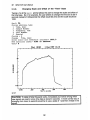
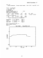
Typing OGR at the Genl> prompt allows the user to perform an overall graph
reduction. In conjunction with GLOB (see section 3.3.11 Changing Global Settings)
the hardcopy displays can be optimized for illustration style output.
3.3.11.
Changing Global Settings
Typing GLOB at the Genl> prompt allows the user to change the two global
parameters CHSC (character height scale divisor) and LCUTLN (turn off page stamp
on all hardcopy). Changing the CHSC parameter may be useful for making the text
on the plots more legible. If either of these affects is desired for hardcopy output only
then the logical names GP4$devtypCHSC and GP4$devtyp LCUTLN can be
redefined before running GENLPLOT. For example
$ DEFINE GP4$QMSIGVCHSC 36
$ DEFINE GP4$QMSIGVLCUTLN FALSE
The following example illustrates the combined effect of performing an overall graph
reduction (see above) and changing the character height scale divisor from its
default of 56 to 36.
Genl> OGR
Enter overall reduction fraction> .5
Genl> GLOB
Enter new character height scale divisor ( 56)> 36
Turn off page stamp on all hardcopy? [yIN)>
<CR>
Genl> P
Shk 1G140
.1
P4
in'
Tuiw.
i-u
.4
0.0
0
0
40
so
Graf><CR>
Geni>
35
00
36
GENLPLOT Users Manual
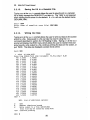
Changing the Point Omission Parameter
3.3.12.
Typing OMIT at the Geni> prompt allows the user to change the point omission
parameter which sets the minimum number of pixels for deviation from a straight line.
The default value for the point omission parameter is 2; a value of zero forces every
point to be plotted.
Genl> OMIT
Enter point omission scale in pixels> 0
Genl>
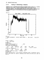
Smoothing the Current Signal
3.3.13.
Enter SMTH at the Geni> prompt allows the user to smooth the current signal using
the three point smoothing algorithm. Smoothing is applied immediately to the
current signal and successive calls result in greater smoothing i.e. 3,5,7,... point
smoothing. There is no automatic labeling to indicate that a signal has been
smoothed. The following example illustrates a curve that has been smoothed once.
Genl> P
1-Aug-1987 14.10
Shot 16140
-8
9L
A4'
o.a
-rILJ
I
D
,
.a
.
20
.
.1
1
40
T rtm,
Graf> SMTH
Genl> P
36
--- ,
60
0
GENLPLOT User's Manual
Shot 16140
1-Aug-1987 14:10
. -
0.0D
20
40
Tkdapo,
37
60
0
37
GENLPLOT Users Manual
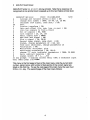
38
Algorithmic Functions
3.4.
The ability to perform specific numerical analyses on the raw data is an option
available to GENLPLOT users. This section outlines command designed to
perform standard functions on the data in the user's kit. Note that the
commands A,G, and Z are defined both immediately and for new signals.
Average and variance within a shot ( A#)
Fourier transform ( F#)
Gain and offset (lin, exp, log, or pwr) ( G#)
Join two signals to form a third
auto/cross correlation ( X#, X#,#)
Zero, subtract baseline ( Z#)
Fit a curve (lin, exp, pwr, or nor) ( FIT#)
average signals over many shots ( SUM###)
A
F
G
J
X
Z
FIT
SUM
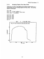
Average and Variance
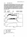
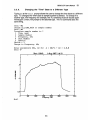
3.4.1.
Entering the letter A at the Genl> prompt allows the user to calculate the
average and variance of the current signal (the command A#, where # is the
number of a signal in the kit, is used for a specific signal) and for any
subsequent signals. For example:
Genl> A
Enter number of points to average over (<CR> to enter times)> 25,40
To plot:
or -1
A
Average
<CR> or 0
Average and Variance
or 1
T
Fluctuation Amplitude
or 2
S
Standard Deviation
Enter flag><CR>
Genl> P
1-Rug-3987 14:10
Shot 16140
D.a
.04
L
C
2
At
0
20
40
'Tinp,
38
N1900
60
6o
GENLPLOT User's Manual
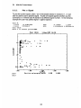
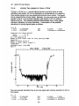
3.4.2.
Fourier Transform
Typing an F at the Genl> prompt allows the user to perform a Fast Fourier
Transform (FFT) on the current signal (using the command F#, where # is the
number of a signal in the kit, allows the user to perform the transform on a
specific signal). The FFT menu allows the user to change the parameters of
the amplitude and frequency, make a hardcopy, initialize, change leakage
reduction, write output to a file and change phase parameters. The power
spectral estimate from the FFT in GENLPLOT is
1 (2At
with
At
N
Xk
Xk,2
N) l
N~
0.875
sampling period
number of samples
same units as input signal
which is
0.875(T
where
At
T
sampling period
total time for transform
Geni> V'
Fourier Transform of CCDIAMBS2P
Time limits> 25,40
Shot 16140
1-Rug-1987 14:10
29
CC
I
I-I
a
CL
1~A.
10
a
Fo.rion tr anDFrrn v i
Fraquanciyj U-1z
leakea rodut ioh buetoo
39
20
25.800
40.OM
39
40
GENLPLOT User's Manual
FFT>
A
F
List of additional
options:
Amplitude, change parameters of
Frequency, change parameters of
Make a hardcopy
H
Initialize
I
L
Leakage
(change time limits,
reduction,
change
R
W
Quit this menu
Replot
Write output to a file
COPY
Make
LAS
PH
Make a hardcopy
Q
retransform,
and plot)
(cosine taper)
a hardcopy
Phase, change parameters of
FFT>
3.4.3.
Gain and Offset
Typing G#, where # is the number of a signal in the kit, at the Genl> prompt
enables the user to change gain and offset parameters for the signal and any
subsequent signals. In the following example the original signal is displayed.
Then, using the G command, an exponential transformation is performed on
the signal.
.
-a
I
.
.
.
Shot 18140
.
.
.
.
.
.:
1-Aug-1987 14:10
.
.
.
I
-
.4
0.0
D
Graf >
. i .
2D
I
-
40
T inae, no
40
a
II
60
i-
-
i
-
a
I
60
-
iI
GENLPLOT User's Manual
Genl> G1
Signal parameters:
Signal:
CCDIAM_BS2P
Time, msec
vs.:
CC DIAM BS2P
CCDIAM_BS2PTM
Number of sample points is
Sample point increment is
Time, msec axis parameters:
IW NW LW
WB
WA
0 4 5
95.0
-5.00
Signal axis parameters:
IS NS LS
SB
SA
1-Aug-1987 14:10
1 Shot 16140
Current signal number
3200
1
DWLT
WFT
-20.0
WSC
20.0
WREF
1.OE-03
0.OE+00
DSLT
SFT
0.400
0 4 3 -0.400
1.10
GAIOFF transformation of CC_DIAM_BS2P
-0.100
flag
flag
flag
flag
* EXP (A*S)
B
Exponential
Linear
Logarithmic
Power law
B + A*S,
ALOG(B + A*S)
A* (S^B)
-1
0
+1
+2
Enter transformation flag: -1
Enter A and B: .25,.5
Genl> P
1-Aug-1987 14; 10
Shot 16140
-19
I
.4
0.0
.
D
.
.
I
.
.
3
.
40
T Ema, r
Graf >
Genl>
41
.
S
3
60
5
5
.
41
3
60
I
42
GENLPLOT Users Manual
3.4.4.
Joining Two signals to Form a Third
Typing a J at the Genl> prompt allows the user to perform either a unary
operation (see section 3.2.9 for a description of all operations) on a signal to
form another signal or join two signals from the kit to form a third. The signal
that is created will be a fixed signal. Naturally, the user must have at least two
signals in the kit to do a binary operation (see section 3.2.2 for adding a
signal to the kit). This following example demonstrates first a unary signal
operation followed by a binary operation. A description of the possible
operations for joining signals goes as follows:
Genl> J
1 16140
3200
4001
CCDIAMBS2P
*CC_NL_BS2P
2 16140
-0.100000
1.10000
0.OOOOOOE+00 0.OOOOOOE+00
Operations for joining signals:
Unary :
/ d r S
Binary:
+ - */
d
S
S3 - [Si] operation S2
Number of first signal (<CR> for unary operation)><CR>
Operation> Number of second signal> 2
Number of third, output, signal> 3
-CC NLBS2P
Alternate signal title><CR>
Genl> P
Shot 16140
-.
I-Aug-1987
a
L.
-. 8
1w I
I
M.
I
111
D
E in.
40
Tr
a,
.
60
.
.
80
The next example illustrates how to join two signal with a binary operation to form a
third signal.
Genl>
J
1 16140
2 16140
3 16140
CCDIAMBS2P
CCNL_BS2P
F *-CCNLBS2P
3200
4001
4001
42
-0.100000
1.10000
0.OOOOOOE+00 0.OOOOOOE+00
-1.OOOOOOE+14
2.OOOOOOE+13
GENLPLOT User's Manual
Operations for joining signals:
/ d r S
Unary :
S
+ - */
d
Binary:
S3 = (511
operation S2
Number
first signal
of
(<CR>
for
unary
operation)>
1
Operation> +
Number of second signal> 2
Number of third, output, signal> 4
CCDIAMBS2P + CCNLBS2P
Alternate signal title><CR>
Genl> p
Shot 16140
I-Aug-1987
.4
0.0-
o.a
D
2D
40
Tima. moo
43
60
80
43
44
GENLPLOT User's Manual
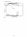
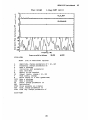
Auto/cross Correlation
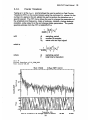
3.4.5.
Typing an x at the Genl> prompt enables the user to perform an auto/crosscorrelation on any two signals or just an autocorrelation on one signal.
Alternatively, the command x#, where # is the number of a signal in the kit, will
perform the autocorrelation on the desired signal. The following example
illustrates the use of the auto/cross correlation function.
Genl> X
1
2
3
4
16140
16140
16140
16140
-0.100000
-1.000000E+13
-1.000000E+14
-1.0000OOE+13
3200
4001
4001
3200
*CCDIAMBS2P
CCNL_BS2P
F
-CCNLBS2P
F CCDIAMBS2P + CC NL BS
1.10000
1.100000E+14
2.0000OE+13
1.100000E+14
Auto/Cross Correlation
Select signal(s)> 1,2
Time limits> 25,40
Shot 16140
'I
-4
1-Aua-1987 14:10
I
U
0
-2
U
2
4
0
(11--
i
L9
-1
.
--
I
I
2
*
*
I
.
*
0
Lag Tine, me
.02[
24
:8
Tiu,
32
Dmtrehdod Signala
XCOR:
<CR> for second page><CR>
44
.
.
I
2
.
4
40
GENLPLOT Users Manual
Shot 16140
1-Aug-1987 14:10
2
ca
.
1v
Fd
1uenou, Wiz
Crcaa oarmrlation betwDan
25.000
XCOR><CR>
XCOR>
A
F
H
I
Q
R
S%
T
W
COPY
LAS
PH
RET
STOR
TAX
TLAX
List of additional
options:
Amplitude, change parameters of ( Al, A2)
Frequency, change parameters of
Make a hardcopy
Initialize (all parameters)
Quit this menu
Replot to the terminal
Signal limits, change ( Sl, S2)
Time limits, change
Write output to a file (QUICK.XCR)
Make a hardcopy
Make a hardcopy
Phase, change parameters of
Retransform
Store analysis as a signal
Time, change parameters of
Time lag, change parameters of
XCOR><CR>
45
A.000
45
46
GENLPLOT Users Manual
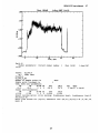
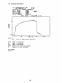
3.4.6.
Zeroing or Subtracting a Baseline
Typing a z or a z#, where # is the number of a signal in the kit, at the Genl> prompt
allows the user to zero or subtract a baseline from the signal and from any
subsequent signals. The zeroing facility allows the user to specify a reference level
or reference line (given in time bounds) over which to compute a baseline to
subtract.
Genl> P
Shot 16140
1-Aug-1987 14;10
.2-
D
20
Genl> Z
Signal parameters:
14:10
Signal:
vs.:
40
s0
TimE, mO
Current signal number
1
60
Shot 16140
1-Aug-1987
CC PPD 4
Time, msec
CC PPD 4
CC PPD_4 TM
Number of sample points is
8000
Sample point increment is
Time, msec axis parameters:
WA
WB
IW NW LW
-15.0
85.0
0
4
5
Signal axis parameters:
SA
SB
IS NS LS
-0.300
0.200
0
2
Reference level time limits
6
1
WFT
DWLT
-20.0
20.0
SFT
DSLT
-0.400
0.100
0.OOOE+00
WSC
WREF
1.OE-03
0.OE+00
40.0
Autoscale ON
Select zeroing option (-1=no zeroing; 0=reference level; 1=reference line)>1
Enter time bounds for [split]
reference line
(TO,T1[,T2,T3])>-5.,0.,65.,70.
Genl> P
46
GENLPLOT User's Manual
Shot 16140
47
1-Aug-1987 14;10
.1 -
D
Genl> Z
Signal parameters:
14:10
2D
40
Current signal number
60
1
GO
Shot 16140
1-Aug-1987
Signal: CC PPD 4
vs.: Time, msec
CC PPD 4
CCPPD_4_TM
Number of sample points is
8000
Sample point increment is
1
Time, msec axis parameters:
WA
WB
IW NW LW
WFT
DWLT
WSC
WREF
-15.0
85.0
0 4 5
-20.0
20.0
1.OE-03 0.OE+00
Signal axis parameters:
SA
SB
IS NS LS
SFT
DSLT
-0.100
0.300
0 2 5 -0.200
0.100
Select zeroing option (-1=no zeroing; 0=reference level; 1=reference line)>1
Autoscale ON
Enter time bounds for [split) reference line (TO,Tl[,T2,T31)>-5.,0.,65.,70.
Genl> P
47
48
GENLPLOT Users Manual
1-Aug-1987 14:10
Shot 16140
.
*
.
*
B
B
B
I............................
-
A
.3a
'U.
10
U
20
40
Time,, --O
48
so
00
GENLPLOT Users Manual
Curve fitting
3.4.7.
Typing FIT at the Genl> prompt allows the user to fit a function to the current
signal in the kit (using the command FIT#, where # is the number of a signal
in the kit, allows the user to perform the transform on a specific signal). The
functions available for fitting are linear exponential, power, or normal.
Genl> FIT
Shot 16140
i
1-Aug-1987 14-10
I
i
I
.8
AI
.4
0.0
D
.I
.I
20
i
- .
40
Tutum. -
.
1
60
,
'
so
Fit: Select L and R points>
After entering the command a plot of the signal will be displayed with a prompt
asking for L (left) and R (right) values. Hit the carriage return and a crosshair
cursor will appear. Position the crosshair cursor over the first value of the
desired interval on the curve and type an L Do the same for the last desired
value of the interval and type an R.
Enter type of fit: O,lin;
l,exp; 2,pwr; 3,nor> 1
Choose the fit (exp, linear, power) desired. A plot similar to the following
example will be displayed.
49
49
GENLPLOT User's Manual
50
YcX) = R30EXFC9%X-Al
(
) 4 FS
X > RI
X d RI
4 A4*(X-Al) &AS
CHISUR - 7.3345W-05
IXDrati.rui = B
U.85167
RCV) =
.639
A(2) - -1.0L1
1.8459
D.084L1
RLI) = 0.SL370
0.5D
1.5753
RC4) = -0.87934
-A
R(5) = 5.79688E-2
I
0.2E-02
Shot 18140
1-u-1987 14: 10
1-Auc-18e7 14.- 10
I
I
I
-
I
.4'.
0.0
I,
Fit> ?
Fit>
COPY
H
LAS
NOTE
R
a
I
-j
rTa..
r
List of additional options:
Make a hardcopy
Make a hardcopy
Make a hardcopy
Write fit info to notepad.
Replot to the terminal
Fit><CR>
Genl>
50
00
go
GENLPLOT Users Manual
3.4.8.
Averaging Signals Over Many Shots
Typing SUM, or SUM###, where ### is a list of signal numbers, at the Genl>
prompt allows the user to average signals over many shots. The resulting
signal is a fixed signal.
Genl> SUM
Enter list of signal numbers> 1
of shot numbers> 16140-16145
Enter list
Start signal:
Start
Start
Start
Start
Start
Start
Genl>
s lot
s lot
s lot
s lot
sthot
sthot
P
CCDIAMBS2P
16140
16141
16142
16143
16144
16145
Shot
j
.
*
5
*
*
*
0
1-Aug-1987
15544
I
I
I
5
TayU avmr shata: lBL.401824L,18142.18143,1144,18145,
5 .41
0.0
I
D
I
Ii
40
TN.
51
.
ft
.
II .
so
I
80
51
52
GENLPLOT User's Manual
Appendix A.
Signal Attributes
There is a specific order of events that occurs when a signal is opened from
the data base. First the signal data is read from the data base, then the time
array is read in. If any of the following actions are defined to occur they do so
in the following order: time is modified, gain and offset are applied, zeroing is
applied, and finally averaging is applied. Each signal has associated with it
many attributes which are stored in the kit and saved with namelist files
including the name of the time signal.
A.1.
Signal Axis Parameters
The following seven signal attributes are determined when autoscaling is in effect. If
the user wishes to change any of the values of these attributes (see section 3.3.4
Signal Axis or section 3.3.8 Changing "Y" axis parameters) only the first three
attributes must be specifically defined for a logarithmicly scaled plot. Redefining
attributes for a linearly scaled plot requires that either five or seven of the attributes
must be explicitly defined.
SA
= BEGINNING SIGNAL AXIS VALUE
SB
- LAST SIGNAL AXIS VALUE
IS
= SCALE FLAG, O=LINEAR, 1=LOGARITHMIC.
NS
= TOTAL NUMBER OF MINOR INTERVALS ( A MULTIPLE OF LS) FOR
LINEARLY SCALED PLOTS, UNLESS SFT AND DSLT ARE
DEFINED, IN WHICH CASE NS = NUMBER OF MINOR INTERVALS
PER MAJOR INTERVAL.
LS
= NUMBER OF LABELED INTERVALS (MAJOR INTERVALS)
SFT
= VALUE OF THE FIRST TIC MARK (OPTIONAL FOR LINEARLY
SCALED PLOTS)
DSLT = DELTA VALUE BETWEEN TICS (OPTIONAL FOR LINEARLY
SCALED PLOTS)
A.2. Zeroing Parameters
ZFL
=
ZEROING FLAG
TO, T1, T2, T3
DEFINE THE ONE OR TWO TIME INTERVALS USED IN
ZEROING.
A.3. Gain and Offset Parameters
G
0
IK
= GAIN (if 0.0 gain and offset is turned off)
= OFFSET
= TYPE OF TRANSFORMATION
52
GENLPLOT Users Manual
A.4. Averaging Parameters
NAV
= AVERAGING
-1
0
0
= START TIME
= DELTA TIME
TS
DT
FLAG
USE DT AND TS
NONE
NUMBER OF POINTS FOR AVERAGING)
FOR AVERAGING
FOR AVERAGING
LFLUC
= SIGNAL DISPLAY FLAG
-1
AVERAGE
0
AVERAGE AND VARIANCE
1
FLUCTUATION INTERVAL (STDEV / AVG)
2
STANDARD DEVIATION
AVTXT
- AVERAGING TEXT IN PANEL
A.5.
Reading Parameters
LREAD
= READ IN SIGNAL
1
YES
0
NO
LABSC
= READ IN ABSCISSA
1
YES
0
NO
LRABSC
= ACCEPT ABSCISSAE KEYBOARD ENTRIES
1
YES
0
NO
A.6. General Signal Parameters
LSIGNL
= NUMBER OF SIGNALS IN KIT.
SIGNAME
= SIGNAL VARIABLE NAME
SIGTITL
= LABEL FOR SIGNAL (ORDINANT) AXIS
TNAME
= NAME OF ABSCISSA VARIABLE
TTITL
= ABSCISSA AXIS LABEL
DATESTR
= DEFAULT PLOT TITLE CONTAINING SHOT NUMBER, DATE, AND
TIME.
JFORMULA
= THE FORMULA FROM DCS COMMAND (see section 3.2.9
Defining a composit signal).
NINC
= SKIP INCREMENT FOR DATA POINTS.
IAS
= AUTOSCALE FLAG
NORMAL
0
1
AUTOSCALE
53
53
54
GENLPLOT Users Manual
SIGNAL TYPE FLAG
-2
COMPOSIT
-1
FIXED
0
REGULAR
1
ARRAYED
IST
=
PNTXT
= OPTIONAL PANEL LABEL
IERR
= SIGNAL ERROR
-1
UNKNOWN SIGNAL
0
OK
1
READ ERROR
DBNAM
= DATA BASE NAME
ITFLG
= ABSCISSA FLAG
1
TIME
2
SAMPLE NUMBER
3
FREQUENCY
4
SHOT NUMBER
5
OTHER
KST
=
SIGNAL PLOT CLASS
Flag Ntim Ndat
0 ns
ns
1 ns
ns
2 ns+1i ns
3 ns+1 ns
( ns=NSAMPL)
Nvar
0
ns
0
ns
54
GENLPLOT Users Manual
Appendix B.
B.A.
55
Abscissa Attributes
Abscissa Axis Parameters
The following seven abscissa attributes are determined when autoscaling is in effect.
If the user wishes to change any of the values of these attributes (see section 3.3.5
Time (Abscissa) Axis ) only the first three attributes must be specifically defined for a
logarithmicly scaled plot. Redefining attributes for a linearly scaled plot requires that
either five or seven of the attributes, must be explicitly defined.
TA
= BEGINNING TIME AXIS VALUE
TB
= LAST TIME AXIS VALUE
Fr
= SCALE FLAG, O=LINEAR, 1=LOGARITHMIC.
NT
= TOTAL NUMBER OF MINOR INTERVALS (A MULTIPLE OF LS) FOR LINEARLY
SCALED PLOTS, UNLESS TFT AND DTLT ARE DEFINED, IN
WHICH CASE NT = NUMBER OF MINOR INTERVALS PER MAJOR
INTERVAL.
LT
= NUMBER OF LABELED INTERVALS (MAJOR INTERVALS)
TFT
= VALUE OF THE FIRST TIC MARK (OPTIONAL FOR LINEARLY
SCALED PLOTS)
DTLT
= DELTA VALUE BETWEEN TICS (OPTIONAL FOR LINEARLY
SCALED PLOTS)
B.2. Abscissa Types
There are 5 types of abscissae: Time, sample number, frequency, shot number, and
other. The default names and units are:
Time, msec
Sample Number
Frequency, kHz
Shot Number
Special
Remember that the time is stored in the database in seconds and frequency in Hertz.
55
56
GENLPLOT User's Manual
Appendix C.
Making a Text String in GP4
The control sequences are used for both in stream commands and to reference the
special centered characters. In general the commands are parameter setting within
a string. The backslash character "\" is used as a delimiter to permit entering the
following control sequences:
Control
Sequence
Function
\#\
plot special character number # in text string
backspace
line feed
new line (\cr\\lf\)
vertical tab
previous line (\cr\\vt\)
carriage return
superscript mode
normal line mode (default)
subscript mode
magnification of default by factor #
e.g. \mag 0.5\
\mag 1.0\
\mag 2.0\
# should contain an explicit decimal point.
regular font (default)
principal fonts
indexical fonts
complex characters (default)
duplex characters
cartographic fonts
latin font
greek font
\bs\
\Rf\
\nl\
\vt\
\pl\
\cr\
\sup\
\no\
\sub\
\mag#\
\reg\
\pri\
\ind\
\cx\
\dx\
\car\
\la\
\gr\
Note that \\ will be interpreted as an actual backslash. Case is ignored in the
commands. For more information see the GRAPAC4 manual. For example the user
can change the signal axis label (see section 3.3.3 Signal Axis) to the following:
Alternate signal title> A\gr\\sub\b
Alternate panel title> \pri\\mag1.5\Diagmagnetism
And the plot will look like this:
56
GENLPLOT Users Manual
Shot 16140
57
1-Aug-1987 14:10
I
'
,
.
Diagmagnetism
.8
.41
0.a
I
.
D
I
.
.
.
. a
I
I
a
2D
I
.
.
60
40
TinG,
.
.
.
80
The following tables of fonts are those available to the user.
Chcracter3 Rvail.able in Subroutine SYMBOL
Complex, Regular, Latin and Greek Fonts
is
j
"a
r
,a21
#
(4"
)41
*
40
'U
&24
U
--P
asa
0.
p 22
P.'
. 2.1
0 3=
Qa aer q Ji
2=. B-. R0.
r 33 ASe
+ III
3M CE' Se
4K D. Tm b02
U SIT *oy in
5s Eu Ui
V 22
+ 2Mt
6:4 Fm V= a
7. Gyi HT g Im w lid X IN
j m
80 HT2 X hSi X 330 xZ 2
Z See
9" In ' Yu i I W J21,
in X 23
Ju 4 ZsW hm Z im
x10
KT% Ein k (IN
<.
.5
.
-4'
I
Nab
/49
>52
0~
1
Lm
3
'E I
\m
Nmo
In n no
^ffi
011
I
127
0i.
%IN
H we
5 um
(2.S3E
IN?
*m2
A 32
x
6mz 41 ..
X3Me
7" . r wo Y 21A
faf
0E
8a&
(1i 214F %,NO
9". I 211 -z2W5 V amm I2M
z
in
xmI372
t 19?
MM2
N
/ W
Intuegr EquivaLuevw 1 L2T arc Irsk
2NTED 0 thru DL cre peoal oenter'ed ourbolo
57
K
22L
0 2L7
0 m Sa
133.
A
4
-10
U 30
M
Tl
22
r
os
4a
0, 221
TM
#we
+
T2=
V 214
V 141
--04
*m N
na
0 02
A mio 9 a ~zu
2L.
P21D
.m
0
(n 22
Mn
2.a 0 To
)m I
1-11
M"
LW
ary
(NO
214
oan
GENLPLOT User's Manual
58
Charaoters Available in Subroutine SYMBOL
Complex, Principal, LAtin. and Greek Fonts
ISO
Oa
14
P .a
M.
'a
(..
) .4'
3
46.
8.
a-
+4.
<?a
b ..
UA
r
Sa
C up
Dn.
Em.
F
T .4
-d sm
U ws
e
V .
f IN
W vr
X im
g s W Lie
h.. 4 x =
YN
i a"
Jy
Z w
Kw
[ 54
L
1.4
=
,/.7
LiM
q LIS
Cw.,
Jim
*.
P
.*
QAl a
A..
2 .
811
-
N,
sDI
B
uS
t
Lid'
U UT
Y
..
1 17?
2 v.
3a11
(h2.4
#316 4 no*
Ssee
6 me
0mu
9
111
t
lay
0No
m Ir .D
P am P a
P Rm
i,..
H in 2 In
17*fl
p-.
QKI.
A xw T = d no -r we.
E iv 7 it z BE U as
m
Cm
D .
eir
Sng
"
2.o
xW.
A
-
.
*m.au
oM0 uw Ja
A
No
I
A;..(=
Sam
As
La d
X ISV
B w
21
tAL
m
A iem
..
7 JaS E m
&a.
a eis
8 1.4 X ow 2 .a 3 'y a
k I
I
'
l95
2W
wm Z UN
f
o
f s
si 3m
V .m Aj
aISa
m
NOt, MfthXIS 3q4v11c4 > 127 Or4 Mreak
Characters Available Tn Subroutine SYMEOL
Duplex, PrInerpal, Latin and Greek Fonte
0.
-
A .
34
2rn
$3.
a7 3L
Em.
81a
F%.
7,
-4.
4r
2
b .u
T.
UV..
S=I
T4
K 7s
L r.
)/4
>1=
?7
N ra
d m. f n.o
O r7
T ins
E
raw
T me
x
+
I me
m
N
n
-3'
rI~m
d:k in1OzIIa.
A os 0 ee
8
2m
4X
P M
10
y in
&IIV7
A ,.. T .
E iv T
ym
X =
in
7 m
-r a
U 2%&
w .v
x
S
9 '.
w
~17Z
-+.?
a 2"
& a&
71,
81..
IE
Om
4 i,
4'.,
1r :.
ans
V23
#135 3 n H1s. E )a
h me
I M
I rT
2 im
r w4
SMs
Wur g 13
(41
0w
qua
R.
C ur
D..
1.1
..
yz.
A,
4346
a2"U
I :a'
a
' -e
X=
n
vo
11
tv
NI Intjer EquNalainee. 5 127 am
el0dc
58
3 2"a
4 IN
N ..
0 Ce
' n
0 l=
Im
v
GENLPLOT Users Manual
Characters Available in Subroutine SYMBOL
Complex, Indeocial, Latin and Greek Fonts
a..
8
D 4.
00"~
P..
i 40
A 05
Qa
B..
R..
b an
S-aa C n.
Ao..
,.w 3"l
4%sy 5-
D..
V..
F.
#5.0
(4K
)
dl
+4
40
7.es
8.. H..
9 wr I ,.
Sof J1
<.
=G0
>..
K,.
Note::
W
LI
LIE
Y
L11
Jip Z
LIN
[K
LIE
V..
111.
-.
botlger
LIS
e Ji U ulF
f A.m V LI.
g in WLID
T.
L ,.
Mn
Om
-b.. .s q1
t
U"
0 i.
ZED
b
Ma.
f! LAOII
X2 J18
X LEE
0 ill.
+ Ion I.-
1 , A to
2 r. R A.. 0..
# INS 3 171 Him
n
4 - A LMT..
Turn
6 m E tor
7 see Ssao
Iff
S"U
&0 a
-t
O ams
17:
Lv',
D
C
r.-N
7 i
-?.".
oe
Opt
01
f
-a
1
so
A ..
MaN.
NJaw
59
Or ON
El
tIn -is
IMquIalftwe > 127 are Grok
.8 ame
I .
I quii
Let
77EvP
.ED
IOU
.21!
Ifek
3-ao
D an
~i.l
59
60
GENLPLOT Users Manual
REFERENCES
1 J.D.
Sullivan "Graphics Package, Version 4: User Reference Manual", PFC Report
RR 84-14, December, 1984.
2T.W.
Fredian and J.A. Stillerman, "MDS/MIT High-Speed Data-Aquisition and
Analysis Software System", Rev. Sci. Instr, 57, 1907 (1986).
3 Marcel
P.J. Gaudreau and James D. Sullivan, "Conceptual Requirements for Large
Fusion Experiment Control, Data, Robotics, and Management Systems",
Proceedings of the IEEE Conference on Real-Time Computer Applications in
Nuclear, Particle and Plasma Physics, in Press, San Fransisco, CA, May 1987.
Sullivan, J.D., Gaudreau, M.P.J., Blanter, B., Fredian, T.W., Irby, J.H., Karcher, C.A.,
Rameriz, R., Sevillano, E., Stillerman, J., and P. Thomas, "The Tara Control,
Monitoring, Data Acquisition and Analysis System, proceedings of the 14th
Symposium on Fusion Technology 1986. Vol. 2, 1491-1498, Avignon, France,
September 8-12, 1986.
Gaudreau, M.P.J., Sullivan, J.D., Fredian, T.W., Karcher, C.A., Sevillano, E.,
Stillerman, J., and P. Thomas, "The Tara Control, Data Acquisition and Analysis
System," proceedings of the IEEE 10th Symposium on Fusion Engineering. Vol. 2,
2010, Philadelphia, PA, December 1983.
4 VersaTerm-PRO
is a registered trademark of Ablebeck Software.
ACKNOWLEGDEMENT
We especially thank Evelio Sevillano and Jim Irby for their encouragement, and
constructive suggestions on what "features" were most needed. We also thank the
entire scientific staff of Tara and single out Bill Guss whose many comments, helpful
but not always appreciated, have improved the program and this writeup.
60
GENLPLOT USER'S MANUAL 61
9/24/87
qualifier 1, 2, 8
range of numbers 6
raw data 14
read in data 18
sample number 13
shot number 10, 13
average signals over many shots 51
current 4
list of all the signals 14
multi-shot plot 29
open a new shot 15
specifying as a qualifier 1
signal 10
add a new signal to the kit 11
arrayed 10, 11, 13
attributes 52
axis parameters 25
composit 10, 13,16
current signal 4, 15
delete 11, 17
fixed 10, 13, 17, 51
multi-signal plot 23
name 1, 10, 11, 52
number 13
plot one signal against another 24
plot the current signal 24
regular 10, 13
reread the same signal 15
specifying as a parameter 1
types 10, 13
smoothing 36
spawn a subprocess 7
square brackets 10
suppress baseline trends 29
TDB command> 14
terminate input 6, 9
text strings 25, 56
time base 13
change the scale and offset of 32
change type 33
frequency 33
sample number 33
shot number 33
V> 27
variance 13, 38
VersaTerm-PRO 3
voice print 27
W> 30
WOD> 20
world-view 29
write out data 20
XCOR> 45
zeroing 46, 52
INDEX
abscissa 25, 26, 30
attributes 55
axis parameters 26
types 13, 55
autocorrelation 44
autoscaling 13, 52, 55
average 27, 38, 52
character height 35
cross correlation 44
crosshair 3, 49
curve fitting 49
database 2, 16, 55
device 1, 7, 8
erase the screen 6
exit 3
FFT 39
power spectral estimate 39
FFT> 40
Fit> 50
fix a signal 17
fluctuation amplitude 29
fonts 56
frequency 13
gain and offset 40, 52
GENL 1
Geni (Menu page 2/2)> 5
Geni (Menu page 1/2)> 4
GenI> 6
Graf> 3
GRAPAC4 1, 2, 3, 56
graph reduction 35
hardcopy 2, 6, 7
histogram 13
join two signals 42
kit 6, 10, 11
add a signal to the kit 10
building a kit 10
delete a signal 11
list contents of 13
reset from namelist file 21
save the kit in namelist file 20
list 6, 10
logical name 2
M> 23
main menu 3, 4, 6
menu display 8, 9
namelist file 1, 20, 21
notepad 9
page stamp 35
point omission 36
61