1
Technical Document
NiagaraAX-3.x CCN Driver User Guide
NIAGARA AX CCN Driver
User Manual
Version No.: 1.0
Date: 11/11/2010
1 Objective .......................................................................................................................... 4
1.1 The CCN Network .................................................................................................... 4
1.2 The CcnDevice.......................................................................................................... 4
1.3 Ccn Shadow Objects ................................................................................................. 4
2 Niagara AX platform ....................................................................................................... 5
3 Quick Start. ...................................................................................................................... 5
4 Operating Modes in CCN ................................................................................................ 6
5 Configure CcnNetwork .................................................................................................... 6
5.1 Add a CcnNetwork ................................................................................................... 6
5.2 Discover and add CcnDevices .................................................................................. 6
6 CCN Architecture ............................................................................................................ 7
7 CCN Network .................................................................................................................. 8
7.1 CCN Network status notes ........................................................................................ 9
7.2 CCN Network monitor notes .................................................................................... 9
7.3 CCN Network views ................................................................................................. 9
7.4 CCN Network Properties .......................................................................................... 9
8 Ccn Device Manager...................................................................................................... 13
9 Ccn Device ..................................................................................................................... 16
9.1Ccn Device Status Properties ................................................................................... 17
9.2 Ccn Device Properties............................................................................................. 17
9.3 CcnDevice property sheet for Status Properties ..................................................... 19
9.4 CcnDevice Property Sheet ...................................................................................... 20
9.5 Table Group selection Properties: ........................................................................... 20
9.6 CcnDevice Actions ................................................................................................. 21
10 Ccn Table Manager ...................................................................................................... 22
11 CcnTable ...................................................................................................................... 26
11.1 CcnTable Configuration........................................................................................ 26
11.2 CcnTable Properties .............................................................................................. 27
11.3 CcnTable Actions.................................................................................................. 30
11.3 CCN table addition ............................................................................................... 30
12 Ccn Point List Manager ............................................................................................... 30
13 Ccn Data Point List Manager ....................................................................................... 31
14 Ccn Alarm History Manager........................................................................................ 34
15 Ccn Fid Point List Manager ......................................................................................... 34
16 Ccn Time Schudule Manager....................................................................................... 36
17 Ccn Points .................................................................................................................... 38
17.1Creating and Configuring the CcnObject .............................................................. 39
17.2 Ccn Object Properties ........................................................................................... 39
18 Actions on CcnObject .................................................................................................. 43
18.1 Set Command ........................................................................................................ 43
18.2 Override Command ............................................................................................... 44
18.3 Auto Command ..................................................................................................... 44
19 Table Polling ................................................................................................................ 49
20 CCN Device Upload .................................................................................................... 50
NIAGARA AX CCN Driver
User Manual
Version No.: 1.0
Date: 11/11/2010
NIAGARA AX CCN Driver
User Manual
Version No.: 1.0
Date: 11/11/2010
21 CCN Device Download ............................................................................................... 50
22 Other Ccn Utility Functions ......................................................................................... 50
22.1 CCN Alarm Acknowledger................................................................................... 50
22.2 CCN Broadcast Acknowledger ............................................................................. 50
22.3 CCN Time Broadcaster ......................................................................................... 50
23 ComfortWorks Tunneling Through JACE................................................................... 51
23 Limitations/Changes made to AX CCN driver ............................................................ 53
24 Performance ................................................................................................................. 53
NIAGARA AX CCN Driver
User Manual
Version No.: 1.0
Date: 11/11/2010
NIAGARA AX CCN Driver
User Manual
Version No.: 1.0
Date: 11/11/2010
1 Objective
The Carrier Communication/Comfort Network which shortly known as CCN driver provides the
components necessary to integrate CCN devices and data into the Niagara environment. The
CCN Driver is made up of three primary components: 1) The CCN Network; 2) The CCN Device
and, 3) a collection of Niagara objects to “shadow” I/O and variables in the CCN network. This is
a serial driver.
1.1 The CCN Network
The CCN Network component is a container object used to track the status of the entire CCN,
track and perform time synchronization between the CCN system and the Niagara system, and
provide support for automatically creating Niagara shadow objects by “learning” devices or
controllers within the CCN.
1.2 The CcnDevice
The CCN Device component is a container object used to track the status of a CCN device, track
and perform time synchronization between the CCN device and the Niagara system, and provide
support for automatically creating Niagara shadow objects by “learning” tables within the CCN
device.
1.3 Ccn Shadow Objects
The CCN driver provides support for several different types of data (much of which is accessible
via the CCN system):
CcnTableGroup: A container within which to organize CcnTable shadow objects
CcnPicTable: A shadow object for the CCN PIC Table type
CcnPocTable: A shadow object for the CCN POC Table type
CcnDataTable: A shadow object for the CCN DataTable type
CcnDataTablewithTimeSchedule: A special shadow object for the CCN DataTable time
schedule type that can be represented either in tabular form as other tables are or
graphically as a time schedule
CcnFidTable: A shadow object for the CCN FidTable type
CcnFidTablewithTimeSchedule: A special shadow object for the CCN FidTable time
schedule type that can be represented either in tabular form as other tables are or
graphically as a time schedule
CcnAHTable: A shadow object for the CCN Alarm History Table type
CcnInputProxy: Shadows the behavior of the CCN Input Point (under a CcnPicTable).
CcnOutputProxy: Shadows the behavior of the CCN Output Point (under a
CcnPicTable, CcnDataTable CcnDataTablewithTimeSchedule, CcnFidTable or
CcnFidTablewithTimeSchedule).
For more clarity on CCN hierarchy refer section 6 “CCN ARCHITECTURE” of this document.
NIAGARA AX CCN Driver
User Manual
Version No.: 1.0
Date: 11/11/2010
NIAGARA AX CCN Driver
User Manual
Version No.: 1.0
Date: 11/11/2010
2 Niagara AX platform
The CCN driver functions either on Windows operating systems, starting with Window 2000
Service Pack 3 and beyond or on QNX operating system. This means the station must run on a
Win-32 based platform, such as a JACE-NXS or -NX, AX Soft JACE, or a PC especially licensed
for the CCN driver or in hard JACE like JACE-2, -4, or -5 and -6 series controller.
Note: This driver supports the single CcnNetwork trunk per station.
3 Quick Start
This section briefly describes how to start with Niagara AX CCN driver.
Create a station from Niagara workbench and do the following.
Open the “ccn” palette and find the CCN Network object.
Paste a CcnNetwork object under the driver’s node in your station.
From CCN network’s “Ccn Network View” edit the bus and element ranges.
Enter the correct comm. port into the field Comm Port.
Note: User should enter only the available ports on a JACE.
Open the CcnDeviceManager view by double-clicking the CcnNetwork object just
added to the station.
o Click the “Discover” button to discover the devices which are available under
CCN Network.
o Select and add the CCN device/s you wish to integrate.
Once a device/s is added, navigate to the “points” folder under the device and
double click the point’s folder to display the CCN “Table Manager” view.
o Click the “Discover” button to discover the tables available under a particular
device
o Select and add Tables to the database. The tables will be added in
categorized manner.
Once the table group/s is added, navigate to the table under a particular table group.
The table can be of type PIC/POC/FID.
For a PIC table do the following
Double click on PIC table. It loads the “Point List Manager” view.
o Click the “Discover” button to discover the points which are available under
that PIC table.
o Select and add the CCN point/s you wish to integrate.
For a POC table do the following
Double click on POC table. It loads the “DataTableManager” view.
o Click the “Discover” button to discover the Data Tables which are available
under that POC table.
o Select and add the CCN Data Table/s you wish to integrate.
o Double click on DataTable which is added under POC table. It loads the
“Data Point List Manager” view
o Click the “Discover” button to discover the points which are available under
that Data table.
o Select and add the CCN point/s you wish to integrate.
NIAGARA AX CCN Driver
User Manual
Version No.: 1.0
Date: 11/11/2010
NIAGARA AX CCN Driver
User Manual
Version No.: 1.0
Date: 11/11/2010
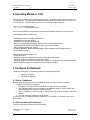
4 Operating Modes in CCN
The CCN Driver supports one of two operating modes. The default mode must have feature “ccnl”
in the license file. For the Extended mode the license feature must include both “ccn” and “ccnl”
in the license file. The Extended mode driver is not offered for sale at this time.
“ccnl”------- ccn standard license.
“ccn + ccnl” ------ ccn extended license
Here’s the major difference between the Standard and Extended versions of the CCN driver:
CCN Standard (license feature ccnl)
- Read/write/force/auto of display table entries
- Read/write set point table entries
- Read/write time schedule table entries
- Discovery (learn/create) support for display, set point, time schedule tables
- Upload/download support for display, set point, time schedule tables
- Alarm handling (display and logging)
- Broadcast date/time, Broadcast acknowledger, Alarm broadcast acknowledger support
- Device status support
CCN Extended (license feature ccn)
- All the above plus
- Additional support for Read/write/force/auto maintenance table entries
- Additional support for Read/write configuration tables
- Additional support for Discovery (learn/create) support for maintenance and configuration tables
- Upload/download support for maintenance and configuration tables
5 Configure CcnNetwork
To add and configure the CcnNetwork, perform the following main tasks:
Add a CCN network
5.2 Discover and add
5.1 Add a CcnNetwork
Use the following procedure to add a CcnNetwork under the station’s Drivers container.
To add an CcnNetwork in the station
1. Double-click the station’s Drivers container, to bring up the Driver Manager.
2. Click the New button to bring up the New DeviceNetwork dialog. For more details, see
“Driver Manager New and Edit” in the User Guide.
3. Select “CcnNetwork,” number to add: 1, and click OK.This brings up a dialog to name the
network.
4. Click OK to add the CcnNetwork to the station.
You should have a CcnNetwork named “CcnNetwork” (or whatever you named it), under your
Drivers folder.
5.2 Discover and add CcnDevices
To discover and add CCN devices do the following
NIAGARA AX CCN Driver
User Manual
Version No.: 1.0
Date: 11/11/2010
NIAGARA AX CCN Driver
Version No.: 1.0
Date: 11/11/2010
User Manual
1. Go to the “Ccn Network View”. Enter the values for properties First Bus No,Last Bus No, Low
Eelement No and High Element No.
2. Double-click the CcnNetwork or right-click the CcnNetwork and select Views
>CcnDeviceManager.
This brings up the Ccn Device Manager.
3. Click on “Discover” button from CcnDeviceManager.
4. It discovers the available CcnDevices which are in the given range.
5. Select the discovered devices and click on “Add” button. It adds up the devices to station
database.
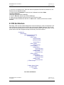
6 CCN Architecture
Essentially, CCN uses the standard Niagara AX network architecture. Under a CcnNetwork it will
have CcnDevice. Normally drivers will have direct points under “Points” extension. But Ccn will
have different table groups under “Points” extension and table resides under table groups. Actual
points reside under table. Diagrammatically the hierarchy would be as follows.
CcnNetwork
|CcnDevice
|Points (Point Device Ext)
|TableGroup1
|PIC Table1
|Control Point1
|Control Point2
:
: Control Point n
|PIC Table2
|Control Point
|POC Table1
|DataTable1
|Control Point1
|Control Point2
|Data Table2
|Control Point
|POC Table2
|DataTable1
|Control Point1
|Control Point2
|Data Table2
|Control Point
|Table Group2
:
:
:
|Alarm History Group
| Alarm Table
| Alarms
Ccn driver architecture
NIAGARA AX CCN Driver
User Manual
Version No.: 1.0
Date: 11/11/2010
NIAGARA AX CCN Driver
User Manual
Version No.: 1.0
Date: 11/11/2010
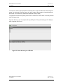
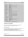
7 CCN Network
For CcnDriver CcnNetwork is the top-level container component in a station. The simplest way to
add a CcnNetwork is from the “Driver Manager” view, using the new command. Or, you can
simply copy the CcnNetwork from the “CCN” palette into Drivers.
Figure1: CcnNetwork from Driver Manager View
NIAGARA AX CCN Driver
User Manual
Version No.: 1.0
Date: 11/11/2010
NIAGARA AX CCN Driver
Version No.: 1.0
Date: 11/11/2010
User Manual
Figure2: CcnNetwork from palette
7.1 CCN Network status notes
As with most other drivers, the status of a CcnNetwork is either the normal “ok” or less typical
“fault” (fault might result from licensing error). The Health slot contains historical timestamp
properties that record the last network status transitions from ok to any other status. The “Fault
Cause” property further explains any fault status.
7.2 CCN Network monitor notes
The CcnNetwork’s monitor routine verifies to Ping the child Ccndevices with ping frequency
duration. For general information, see “About Monitor” in the User Guide.
7.3 CCN Network views
The CcnNetwork’s default view is Ccn Device Manager, equivalent to the Device Manager in
most other drivers. Use this view to discover and add Ccn Device components to the station.
Another view is Ccn Network View which is equivalent to property sheet.
Other standard views are also available on the CcnNetwork. However, apart from the Ccn
Device Manager, we typically access only its Ccn Network View.
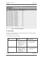
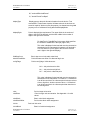
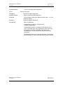
7.4 CCN Network Properties
NIAGARA AX CCN Driver
User Manual
Version No.: 1.0
Date: 11/11/2010
NIAGARA AX CCN Driver
Version No.: 1.0
Date: 11/11/2010
User Manual
retryCount:
Indicates how many additional times a request for data will
be sent to the CCN if the first attempt fails or the answer
contains an error. The recommended setting for this driver
is “1”, which allows for up to 2 attempts before declaring a
communications error.
responseTimeOut(sec)
Indicates how long the driver will wait for a response before
declaring the CCN non-responding. On a poll/response
sequence, if the response does not return within the
responseTimeOut period, a retry is attempted. If retryCount
has been exhausted, a communications failure is declared.
Recommended setting is 2-5 seconds
clearBridgeList
During the learn process, the user can specify that the
bridges list be cleared and start over.
createTables
During the create process, the user can specify that
CcnTables are automatically created for all tables under all
devices that have been selected for CcnDevice creation.
autoCreatePoints
Boolean value, “true” if station is to auto create points when Pic
and or Data and or FID IO tables are created. Only supports
creation of points under Status Display (11H) and FID Status
table (501H).
bridges
A list of the known bridge addresses
learnStatus
Status of network level learn command (busy, idle, or error).
firstBusNo
The starting bus address to be used in the learn process.
lastBusNo
The ending bus address to be used in the learn process.
lowElemNo
The starting element address to be used in the learn process.
hiElemNo
The ending element address to be used in the learn process.
deviceLearnCount
Number of devices found during latest learn process
displayMetric
At any time the user can change the units display of all
values between Metric and Imperial.
UnsolicitedReceiveHandler
Handler for unsolicited messages.
alarmAcknowledger
Checkbox, select if JACE to be the CCN Network alarm
acknowledger, de-select if not.
broadcastAcknowledger
Boolean value, select “true” if JACE to be the CCN Network
broadcast acknowledger, “False” if not.
NIAGARA AX CCN Driver
User Manual
Version No.: 1.0
Date: 11/11/2010
NIAGARA AX CCN Driver
User Manual
timeSyncStat
Version No.: 1.0
Date: 11/11/2010
Reports if time sync service is started or stopped.
timeBroadcaster
Checkbox, select if station is to be the CCN Network time
broadcaster.
timeSyncDisplayDots
Normally set to False, setting to True will enable a “T”
character to displayed in the diagnostic output every
timeSync cycle.
busAddress
The CCN bus address that the Niagara Station is connected
to (generally the primary bus, bus 0).
elemAddress
The CCN element address on the busAddress that the
Niagara Station is assigned (generally a high element
number just below the broadcast address range, typically
230 - 239). Do not use same address assigned to Comfort
Works application that you might decide to tunnel for setup
and configuration.
tunnelEnable
checkbox, select to enable tunneling for the JACE. Since
tunneling consumes station resources in order to maintain
IP communications to ComfortWorks stations, it is
recommended that this feature be disabled unless
tunneling of ComfortWorks is required. It is not
recommended to leave tunneling enabled “just in case”
one might someday wish to tunnel a ComfortWorks.
CcnTunnelHelper
Tunnel Helper component which contains tunnel related
properties as mentioned below
tunnelRxDisplayDots
Normally set to False, setting to True will enable a “B”
character to be displayed in the diagnostic output every
tunnel-receive cycle.
tunnelTxDisplayDots
Normally set to False, setting to True will enable a “U”
character to be displayed in the diagnostic output every
tunnel-transmit cycle.
tunnelRxDebugOn
Selects whether tunnel-receive debug is turned on or off.
If set to "True", protocol specific debug text will be
generated and sent to the administrator console window
whenever tunnel data is received by the JACE from a
ComfortWorks.
tunnelTxDebugOn
Selects whether tunnel-transmit debug is turned on or off.
If set to “True”, protocol specific debug text will be
generated and sent to the administrator console window
whenever tunnel data is transmitted to a ComfortWorks
from the JACE.
NIAGARA AX CCN Driver
User Manual
Version No.: 1.0
Date: 11/11/2010
NIAGARA AX CCN Driver
User Manual
Version No.: 1.0
Date: 11/11/2010
tunnelRxRetryCount
When the JACE sends tunnel data to a ComfortWorks, it
expects an acknowledgement of receipt from the
ComfortWorks. In the event that the JACE sends tunnel
data to a ComfortWorks but does not receive any such
acknowledgement, this parameter defines the number of
times that the JACE should resend the packet of data. The
recommended setting for this property is two retries.
tunnelRxRetryTimeout (ms)
When the JACE sends tunnel data to a ComfortWorks, it
expects an acknowledgement of receipt from the
ComfortWorks. This parameter defines the number of
milliseconds that the JACE should wait for the
acknowledgement of receipt from the ComfortWorks. If the
acknowledgement of receipt is not received during this
interval of time after transmission, then the JACE will retry
the number of times specified by the property
tunnelRxRetryCount. The recommended setting for this
property is 1000 milliseconds.
lowLevelDebug
Boolean property, “true” if JACE to be the CCN Network
broadcast acknowledger, false if not. If selected, low level
native code specific debug text will be generated and sent
to the administrator console window.
lowLevelDebugMask
Default is 0. Do not use this property without the assistance
of Tridium Engineering (in an effort to isolate a specific
problem you have reported).
commPort
Comm port through which communications to the CCN will
take place. User should enter one of the available port on
JACE to which CCN trunk has connected to.
HostbaudRate
Set to match the baud rate of the bus of the CCN Network
to which the JACE is connected, default is 9600.
NIAGARA AX CCN Driver
User Manual
Version No.: 1.0
Date: 11/11/2010
NIAGARA AX CCN Driver
Version No.: 1.0
Date: 11/11/2010
User Manual
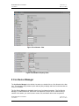
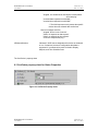
Figure 3 Ccn Network View
Figure 4 CcnNetwork Property sheet
8 Ccn Device Manager
The Ccn Device Manager is the default view when you double-click on a Ccn Network in the Nav
tree. This manager view provides a quick and easy way to display and learn Ccn devices that are
on the Ccn network:
The Ccn Device Manager is the default view for any Ccn Network container. The Ccn Device
Manager is a table-based view, where each row represents a unique device. When building a
network in the station, you use this view to create, edit, and delete device-level components.
NIAGARA AX CCN Driver
User Manual
Version No.: 1.0
Date: 11/11/2010
NIAGARA AX CCN Driver
User Manual
Version No.: 1.0
Date: 11/11/2010
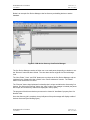
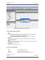
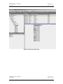
Below is an example Ccn Device Manager view for discovery and adding devices to station
database.
Figure 5: CCN device discovery from Device Manager
The Ccn Device Manager consists of either one or two main panes, depending on whether or not
the “Discover” button has been clicked. The view above shows a typical Ccn Device Manager
view.
The “New Folder”, “New”, and “Edit” buttons are not unique to the Ccn Device Manager, and are
explained in the “Niagara AX User’s Guide” in the “Driver Architecture” section. The “Match”
button is not used for the Ccn driver.
The “Discover” button does implement functionality that is unique and tailored to discovering Ccn
devices. By clicking the “Discover” button, the “learn” mode of the manager is invoked (the panes
will be split, and a “discovery” table will be displayed in the top pane) .
The progress of the discover devices process can be viewed in “learnStatus” property from Ccn
Network View.
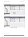
Once the discovery job is complete, the top half-pane of the point manager will display a table of
devices discovered (see following figure).
NIAGARA AX CCN Driver
User Manual
Version No.: 1.0
Date: 11/11/2010
NIAGARA AX CCN Driver
User Manual
Version No.: 1.0
Date: 11/11/2010
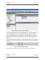
Figure 6: Adding CcnDevice to station database.
If you highlight one or more rows in the top “Discovered” pane, then “Add” button becomes active.
You can now add the selected devices to the station database by clicking the “Add” button.
Note: As in Normal drivers, the CCN driver doesn’t open a dialog window before adding the
learned entry to station database. Simply it adds the entry to station database. If user wants to
edit anything (deviceName/busNum/elementNum), user can do the same by clicking on “Edit”
button
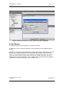
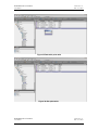
If user selects the property “createTables” as “true” and “autoCreatePoints” as “true”, then tables
will be discovered and the points which are under “Status Display” group will be added along with
the device.
Figure 7: Auto create Tables and Points
The user can add a ccn device by using the “new” button from the Ccn Device Manager.
NIAGARA AX CCN Driver
User Manual
Version No.: 1.0
Date: 11/11/2010
NIAGARA AX CCN Driver
User Manual
Version No.: 1.0
Date: 11/11/2010
Figure 8: Adding a CcnDevice by “New” option from CcnDeviceManager
9 Ccn Device
A CcnDevice object can only be added to a CcnNetwork container.
A CcnDevice is most conveniently added during the CcnNetwork’s Device Manager Creation
process.
Alternatively, a CcnDevice may be added to an existing station using the “New” button on Device
Manager. To do so, drag and drop the CcnDevice object from palette to Ccnnetwork under
station. This will add the CcnDevice to the CcnNetwork. If this approach is taken, the user will
need to go to the CcnDevice Config tab and set the busNo, elemNo properties to the actual
address of the device to be shadowed. Then, a “fetch” action on device will retrieve additional
needed device information like pic type , part no, model no etc.
NIAGARA AX CCN Driver
User Manual
Version No.: 1.0
Date: 11/11/2010
NIAGARA AX CCN Driver
Version No.: 1.0
Date: 11/11/2010
User Manual
Figure 9: Adding CcnDevice from the palette
9.1Ccn Device Status Properties
Status
Status of CcnNetwork communications to this CcnDevice. Possible status flags include:
o Ok - Normal communications, no other status flags.
o Disabled - Enabled property is set to false, either directly or in CcnNetwork.
o Down - Error communicating to the CcnNetwork.
Enabled
Either true (default) or false. Can be set directly or in parent CcnNetwork. See Status
disabled description above.
Health
Contains properties including timestamps of last “ok” time and last “fail” time, plus a string
property describing last fail cause.
Fault Cause
If status has fault, describes the cause.
9.2 Ccn Device Properties
busNo
The bus address of the device.
elemNo
The element address of the device.
deviceName
Retrieved from the device with the fetch command
NIAGARA AX CCN Driver
User Manual
Version No.: 1.0
Date: 11/11/2010
NIAGARA AX CCN Driver
Version No.: 1.0
Date: 11/11/2010
User Manual
picType
Retrieved from the device with the fetch command.
applicationVersion
Retrieved from the device with the fetch command
deviceStatus
Shows whether the device is online or offline.
deviceDescription
Retrieved from the device with the fetch command
location
Retrieved from the device with the fetch command
partNo
Retrieved from the device with the fetch command.
modelNo
Retrieved from the device with the fetch command.
serialNo
Retrieved from the device with the fetch command.
referenceNo
Retrieved from the device with the fetch command.
platformNo
Retrieved from the device with the fetch command.
osVersion
Retrieved from the device with the fetch command.
deviceType
Shows whether the device is of type “Bridge” or “NonBridge”
primaryBaudRate Retrieved from the device with the fetch command.
secondaryBaudRate
maxTableNumber
tableLearnCount
Retrieved from the device with the fetch command.
The CcnDevice’s TableListManager learn process will attempt to
learn the maxTableNumber of a device. This is beneficial,
because it will shorten the learn process Some devices do
not support the technique used to automatically learn the
maxTableNumber, so the user is permitted to enter this
value if it is known.
Number of tables learned/discovered during latest discovery
process.
learnStatus
Status of controller level learn command (busy, idle, or error).
tableCreateCount
Number of tables created during latest create process
deviceTime
devicePingStatus
The latest device date and time as returned in response to a
query of the device’s Date Time Table sent by the ping process.
Device date and time are not used by Niagara for any purpose
other than a short and quick message to perform a device status
check, so if they are not current and the next property
(devicePingStatus) indicates "skipped, not needed since child
object communicated since last ping", that is good sign in that
adequate successful comm activity is occurring and the devicePing
that updates deviceTime is not required to run.
The success or failure status of the device ping.
The ping process alternately retrieves the date and the time
block. A success messages would be:
"succeeded and parsed date from ping message"
"succeeded and parsed time from ping message"
NIAGARA AX CCN Driver
User Manual
Version No.: 1.0
Date: 11/11/2010
NIAGARA AX CCN Driver
Version No.: 1.0
Date: 11/11/2010
User Manual
"skipped, not needed since child object communicated
since last ping"
"received date response but with NAK "
"received time response but with NAK "
** The NAK response merely means the specific
device does not maintain date and/or time.
Failure messages would be:
"skipped, device is out of service"
"failed, no response to date request"
"failed, no response to time request"
"could not complete last ping: "
isEnhancedVersion
Indicates if JACE license designates this device as enhanced
or not. If enhanced, access to configuration table data is
supported. If not enhanced, access is limited to Display,
Setpoint, and Time Schedule Data.
The CcnDevice’s property sheet
9.3 CcnDevice property sheet for Status Properties
Figure 10: CcnDevice Property sheet
NIAGARA AX CCN Driver
User Manual
Version No.: 1.0
Date: 11/11/2010
NIAGARA AX CCN Driver
User Manual
Version No.: 1.0
Date: 11/11/2010
9.4 CcnDevice Property Sheet
Figure 11: CcnDevice Property sheet
9.5 Table Group selection Properties:
User can select the type of table group he wants to discover. The Table groups which are
selected as “true” will be learned in the discovery process. The table groups which are selected
as “false” will not be learned in the discovery process.
NIAGARA AX CCN Driver
User Manual
Version No.: 1.0
Date: 11/11/2010
NIAGARA AX CCN Driver
User Manual
Version No.: 1.0
Date: 11/11/2010
Figure 12: Table Group selection from CcnDevice Property sheet
Following are the Table Groups support by a FID type device
9.6 CcnDevice Actions
Ping: Pings the Ccn device and updates device ping status property.
Upload:
A CcnDevice’s CcnPicTables, CcnPocTables, CcnDataTables and CcnFidTables can be
uploaded. The upload command is available as an action on the CcnDevice. When invoked, a list
of CcnTables blocks are uploaded and all Station resident data is updated to match that which
was retrieved from the field device.
Download:
A CcnDevice’s CcnPicTables, CcnPocTables, CcnDataTables and CcnFidTables can be
downloaded. The download command is available as an action on the CcnDevice. When
selected, each non-real-time table’s value blocks are constructed from the Station resident data
and then downloaded to the field device.
Note: If download the logic to the controller, we don’t have clarity on whether the device will work
or not. So we couldn’t test this feature.
Fetch:
This action will fetch additional information of device when user manually adds a new device with
correct bus and element numbers.
NIAGARA AX CCN Driver
User Manual
Version No.: 1.0
Date: 11/11/2010
NIAGARA AX CCN Driver
User Manual
Version No.: 1.0
Date: 11/11/2010
Figure 13 Actions on CcnDevice
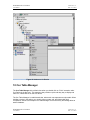
10 Ccn Table Manager
The Ccn Table Manager is the default view when you double-click on “Point” extension under
Ccn Device in the Nav tree. This manager view provides a quick and easy way to display and
learn Ccn Tables that are on the Ccn device:
The Ccn Table Manager is a table-based view, where each row represents a unique table. When
building a device in the station, you use this view to create, edit, and delete table-level
components. Below is an example Ccn Table Manager View for discovery and adding tables to
station database.
NIAGARA AX CCN Driver
User Manual
Version No.: 1.0
Date: 11/11/2010
NIAGARA AX CCN Driver
Version No.: 1.0
Date: 11/11/2010
User Manual
The Ccn Table Manager consists of either one or two main panes, depending on whether or not
the “Discover” button has been clicked. The view above shows a typical Ccn Table Manager
view.
The “New Folder”, “New”, and “Edit” buttons are not unique to the Ccn Table Manager, and are
explained in the “Niagara AX User’s Guide” in the “Driver Architecture” section. The “Match”
button is not used for the Ccn driver.
The “Discover” button does implement functionality that is unique and tailored to discovering Ccn
tables. By clicking the “Discover” button, the “learn” mode of the manager is invoked (the panes
will be split, and a “discovery” table will be displayed in the top pane) .
The progress of table discovery can be viewed from “learnstatus” property from Ccn Table
Manager.
Once the discovery job is complete, the top half-pane of the Ccn Table Manager will display a
collection of tables discovered (see following figure).
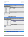
Figure 14: CcnTable Discovery
NIAGARA AX CCN Driver
User Manual
Version No.: 1.0
Date: 11/11/2010
NIAGARA AX CCN Driver
User Manual
Version No.: 1.0
Date: 11/11/2010
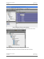
Figure15: Adding CcnTables to station database
Once the user clicks on “Add” all tables will be added in a category manner under a device.
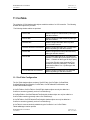
Figure 16: CcnNetwork hierarchy after adding tables to the device.
If the table type is POC table, we can discover the Data Tables under a POC table.
NIAGARA AX CCN Driver
User Manual
Version No.: 1.0
Date: 11/11/2010
NIAGARA AX CCN Driver
User Manual
Version No.: 1.0
Date: 11/11/2010
Figure17: CcnDataTable Discovery
Figure 18: Adding Data Tables under POC table.
NIAGARA AX CCN Driver
User Manual
Version No.: 1.0
Date: 11/11/2010
NIAGARA AX CCN Driver
Version No.: 1.0
Date: 11/11/2010
User Manual
11 CcnTable
The collection of CCN shadow table objects model the tables of a CCN controller. The following
shadow table objects are provided:
The following shadow tables are provided:
CcnPicTable
Models a single Pic table defined by table type
and table instance.
CcnPocTable
Models a single Poc table defined by table type
and table instance.
CcnDataTable
Models a single Data table defined by table
type and table instance.
CcnDataTableWithTimeSchedule
Models a single Data table with Time Schedule
defined by table type and table instance.
CcnAHTable
Models a single Alarm History table defined by
table type and table instance.
CcnFidTable
For IO Points table type 501H, one table entry
(instance 1) models all IO point tables (up to 64
points - 1 instance of table type 501H per point)
For all other Fid table types supported (Time
Schedules, Setpoints, Holidays) , Fid Tables
model device tables 1 for 1 by table type and
table instance
CcnFidTableWithTimeSchedule
Models a single Fid table with Time Schedule
defined by table type and table instance.
11.1 CcnTable Configuration
The CcnTable shadow object consists of CcnPicTable, CcnPocTable, CcnDataTable,
CcnDataTablewithTimeSchedule, CcnFidTable, CcnFidTablewithTimeSchedule, and
CcnAHTable shadow objects.
A CcnPicTable or CcnPocTable or CcnAHTable shadow object can only be added to a
CcnDevice container (generally under a CcnTableGroup).
A CcnDataTable or CcnDataTablewithTimeSchedule shadow object can only be added to a
CcnPocTable container (generally under a CcnTableGroup).
A CcnFidTable or CcnFidTablewithTimeSchedule shadow object can only be added to a
CcnDevice container (generally under a CcnTableGroup)
A CcnTable is most conveniently added during the CcnDevice’s or CcnPocTables
TableListManager creation process
NIAGARA AX CCN Driver
User Manual
Version No.: 1.0
Date: 11/11/2010
NIAGARA AX CCN Driver
Version No.: 1.0
Date: 11/11/2010
User Manual
Alternatively, a CcnTable may be added to an existing station using the copy-and-paste method.
To do so:
-
From Ccn Table Manager, add a table to table group by using “new” button.
This will add the CcnTable to the CcnDevice or CcnPocTable
set the CcnTable tableType and tableInstance properties to the actual type and instance
of the table to be shadowed (must enter these in decimal, not hex)
if table type is set to 501H for Fid IO points, be sure and set the instance to 1
if the table type is CcnDataTable or CcnDataTableWithTimeSchedule, user must also set
the blockNumber
do a fetch command (on the Menu bar under commands or at the bottom of the view) will
retrieve additional needed table information and build the pointList.
Note: Table name “SPSCHPOC” will not support manual addition of table and fetching.
11.2 CcnTable Properties
Table Type
Table’s table type. The valid values are
Pic tables (16 {10H], 17 {11H}, 18{12H}, 19{13H}, 23{17H})
Poc tables (20 {14H], 21 {15H}, 22{16H}, 24{18H})
AH tables (67 {43H})
Data tables (> 127)
tableTypeString
The table’s table group type.
tableInstance
Table’s table instance number.
tableNumber
Table’s unique table number.
tableName
Table’s 8 character table name. This is the only property which goes to
field device. After changing the table name from property sheet, user
should invoke “fetch” action on table. Then the table name will change to
the new name given by user. Invalid table name will be treated as “T”.
First 8 characters of the name will go to the field device.
Note: User should change the tableName property from property sheet only. Try to avoid
renaming the table name from wire sheet, slot sheet etc.
Observation: This operation is controller specific.
tableBlockCount
Table’s block count (generally 10-15).
learnStatus
Status of controller level learn command (busy, idle, or error).
NIAGARA AX CCN Driver
User Manual
Version No.: 1.0
Date: 11/11/2010
NIAGARA AX CCN Driver
Version No.: 1.0
Date: 11/11/2010
User Manual
pointLearnCount
Number of points found during latest learn process
pointCreateCount
Number of points created during latest create process
For a POC table additional properties are
dataTableType
type of datatable which resides beneath it.
dataTableLearnCount
Number of data tables found during latest learn process
dataTableCreateCount
Number of data tables created during latest create process
For a Data Table
dataBlock
The data block in the data table where this point data values are
located
Figure 19: Property sheet for the Ccn PIC table
NIAGARA AX CCN Driver
User Manual
Version No.: 1.0
Date: 11/11/2010
NIAGARA AX CCN Driver
User Manual
Version No.: 1.0
Date: 11/11/2010
Figure 20: Property sheet for the CCN POC table
Figure21: property sheet for the CCN Data Table
NIAGARA AX CCN Driver
User Manual
Version No.: 1.0
Date: 11/11/2010
NIAGARA AX CCN Driver
User Manual
Version No.: 1.0
Date: 11/11/2010
11.3 CcnTable Actions
Fetch: fetches the additional table related information. Please refer the table Name property from
section 11.2
11.3 CCN table addition
12 Ccn Point List Manager
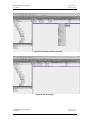
The Ccn Point List Manager is the default view when you double-click on “PIC” table which is
placed under a CcnTableGroup in the Nav tree. This manager view provides a quick and easy
way to display and learn Ccn Points that are on the Ccn PIC table:
The Ccn Point List Manager is a table-based view, where each row represents a unique point.
When building a device in the station, you use this view to create, edit, and delete point-level
components. Below is an example Ccn Point List Manager View for discovery and adding points
to station database.
Figure 22: CCN PIC table’s Point discovery
The Ccn Point List Manager consists of either one or two main panes, depending on whether or
not the “Discover” button has been clicked. The view above shows a typical Ccn Point List
Manager view.
NIAGARA AX CCN Driver
User Manual
Version No.: 1.0
Date: 11/11/2010
NIAGARA AX CCN Driver
User Manual
Version No.: 1.0
Date: 11/11/2010
The “New”, and “Edit” buttons are not unique to the Ccn Point List Manager, and are explained in
the “Niagara AX User’s Guide” in the “Driver Architecture” section. The “Match” button is not
used for the Ccn driver.
The “Discover” button does implement functionality that is unique and tailored to discovering Ccn
points. By clicking the “Discover” button, the “learn” mode of the manager is invoked (the panes
will be split, and a “discovery” table will be displayed in the top pane) .
The progress of the discover points process can be viewed from “learn status” from table’s
property sheet.
Once the discovery job is complete, the top half-pane of the point manager will display a table of
points discovered.
Figure 23: Adding Ccn Points to station database
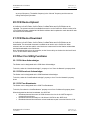
13 Ccn Data Point List Manager
The Ccn Data Point List Manager is the default view when you double-click on “Data” table
which is place under a POC table in the Nav tree. This manager view provides a quick and easy
way to display and learn Ccn Points that are on the Ccn POC table:
The Ccn Data Point List Manager is a table-based view, where each row represents a unique
point. When building a device in the station, you use this view to create, edit, and delete pointlevel components. Below is an example Ccn Data Point List Manager View for discovery and
adding points to station database.
NIAGARA AX CCN Driver
User Manual
Version No.: 1.0
Date: 11/11/2010
NIAGARA AX CCN Driver
User Manual
Version No.: 1.0
Date: 11/11/2010
The Ccn Data Point List Manager consists of either one or two main panes, depending on
whether or not the “Discover” button has been clicked. The view above shows a typical Ccn Data
Point List Manager view.
The “New”, and “Edit” buttons are not unique to the Ccn Point List Manager, and are explained in
the “Niagara AX User’s Guide” in the “Driver Architecture” section. The “Match” button is not
used for the Ccn driver.
The “Discover” button does implement functionality that is unique and tailored to discovering Ccn
points. By clicking the “Discover” button, the “learn” mode of the manager is invoked (the panes
will be split, and a “discovery” table will be displayed in the top pane) .
The progress of the discover points process can be viewed from “learn status” from table’s
property sheet.
Once the discovery job is complete, the top half-pane of the point manager will display a table of
Points discovered.
Figure 24: Points discovery on CcnDataTable.
NIAGARA AX CCN Driver
User Manual
Version No.: 1.0
Date: 11/11/2010
NIAGARA AX CCN Driver
User Manual
Version No.: 1.0
Date: 11/11/2010
Figure 25: Adding Points to station database.
NIAGARA AX CCN Driver
User Manual
Version No.: 1.0
Date: 11/11/2010
NIAGARA AX CCN Driver
Version No.: 1.0
Date: 11/11/2010
User Manual
14 Ccn Alarm History Manager
Ccn alarm history manager is the default view for a alarm history table. It is as follows.
Figure 26 Alarm History Table
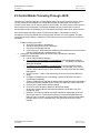
15 Ccn Fid Point List Manager
The Ccn Fid Point List Manager is the default view when you double-click on FID table which is
learnt from an FID type device. This manager view provides a quick and easy way to display and
learn Ccn Points that are on the Ccn Fid Table:
The Ccn Fid Point List Manager is a table-based view, where each row represents a unique point.
When building a device in the station, you use this view to create, edit, and delete point-level
components. Below is an example Ccn Fid Point List Manager View for discovery and adding
points to station database.
The Ccn Fid Point List Manager consists of either one or two main panes, depending on whether
or not the “Discover” button has been clicked. The view above shows a typical Ccn Fid Point List
Manager view.
The “New”, and “Edit” buttons are not unique to the Ccn Fid List Manager, and are explained in
the “Niagara AX User’s Guide” in the “Driver Architecture” section. The “Match” button is not
used for the Ccn driver.
NIAGARA AX CCN Driver
User Manual
Version No.: 1.0
Date: 11/11/2010
NIAGARA AX CCN Driver
User Manual
Version No.: 1.0
Date: 11/11/2010
The “Discover” button does implement functionality that is unique and tailored to discovering Ccn
points. By clicking the “Discover” button, the “learn” mode of the manager is invoked (the panes
will be split, and a “discovery” table will be displayed in the top pane) .
The progress of the discover points process can be viewed from “learn status” from that particular
table’s property sheet.
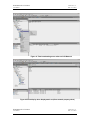
Once the discovery job is complete, the top half-pane of the point manager will display a
table of points discovered.
Figure 27 Point’s discovery on a FID table
NIAGARA AX CCN Driver
User Manual
Version No.: 1.0
Date: 11/11/2010
NIAGARA AX CCN Driver
User Manual
Version No.: 1.0
Date: 11/11/2010
Figure 28 Adding points to station database.
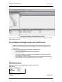
16 Ccn Time Schudule Manager
CcnTimeScheduleManager is a tabular view which will be available on tables of type
DataTableWithTimeSchedule or on tables of type FIDTableWithTimeSchedule.From this tabular
view user can select/deselect the check boxes available under week days and can change the
time under fields “From” and “To”. User can save these values to the controller by using
“SaveTimeSchdules” option. The changes will be reflected in Ccn Fid PointList manager.
The changes done in CcnFidPointList manager will be reflected in CcnTimeScheduleManager
and vice versa.
The screen shot for Ccn Time schedule Manager is as follows.
NIAGARA AX CCN Driver
User Manual
Version No.: 1.0
Date: 11/11/2010
NIAGARA AX CCN Driver
User Manual
Version No.: 1.0
Date: 11/11/2010
Figure 29: Ccn Time Schedule Manager
NIAGARA AX CCN Driver
User Manual
Version No.: 1.0
Date: 11/11/2010
NIAGARA AX CCN Driver
Version No.: 1.0
Date: 11/11/2010
User Manual
Figure 30 Ccn Fid Point List Manager
17 Ccn Points
The collection of CCN shadow point objects model the real and internal I/O as well as selected
internal modules of a CCN controller.
The following shadow objects are provided.
Type
Behavior
Where it is valid
CcnInputProxy
Models a single Input
Point defined by field index
and field name in the
table.
An Input Point is one that
is not forceable or
writeable.
under CcnPicTable types
11H and 12H (applies to
non-forcible points)
Models a single foceable
Output Point defined by
field index and field name
in the table.
An Output Points is one
that is forceable.
under CcnPicTable types
11 H and 12H (applies to
forcible points),
CcnOutputProxy
NIAGARA AX CCN Driver
User Manual
Version No.: 1.0
Date: 11/11/2010
NIAGARA AX CCN Driver
Version No.: 1.0
Date: 11/11/2010
User Manual
The user can select the
Force and Auto
commands.
Or
CcnFidOutputProxy
Models a single nonforceable Output Point
defined by field index and
field name in the table.
A Non-forceable Output
Point is one that is not
forceable, but is settable.
The user can select the
setValue command.
Models a single Output
Point defined by field index
and field name in the
table.
An Output Points is one
that is forceable.
The user can select the
Force and Auto
commands.
under CcnPicTable types
10H and 13H, or 17H
under CcnDataTable
types that are under
CcnPocTable types 14H,
16H, or 18H
under CcnFidTable types
501H
17.1Creating and Configuring the CcnObject
A CcnObject can only be added during the CcnPicTable, CcnDataTable’s or CcnFidTable
PointListManager addition process
17.2 Ccn Object Properties
fieldIndex
CcnPicTable and CcnDataTable can have up to 60 points with field Index
ranging from 0-59
Fid IO_ Points Tables can have up to 64 points with field Index ranging
from 0-63
Fid Set point Tables can have up to 4 points with field Index ranging from
0-3
Fid Time Schedule Tables can have up to 21 points with field Index
ranging from 0-20
Fid Holiday Tables can have up to 60 points with field Index ranging from
0-59
fieldName
this point’s name (8 ASCII characters)
NIAGARA AX CCN Driver
User Manual
Version No.: 1.0
Date: 11/11/2010
NIAGARA AX CCN Driver
User Manual
Version No.: 1.0
Date: 11/11/2010
Fid IO_Points Tables has up to 64 points. Each point’s name can be
modified from Niagara by changing it from the property sheet and invoke
“fetch” action.
dataType
Point’s data type (00 – 33H).
dataTypeEnum
Point’s data type enumeration.
0, "eightBitFlags"
1, "unsignedChar"
2, "unsignedInt"
6, "BEST_FloatingPoint"
7, "IEEE_FloatingPoint"
9, "signedChar"
10, "signedInt"
12, "timeInTwoBytes"
16, "Name"
17, "BCD"
18, "controllerName"
19, "controllerName"
20, "controllerName"
21, "controllerName"
22, "pointName"
23, "pointName"
24, "pointName"
25, "schedulePointNo"
26, "schedulePointNo"
27, "schedulePointNo"
28, "schedulePointNo"
29, "schedulePointNo"
30, "schedulePointNo"
31, "schedulePointNo"
32, "phoneNumber"
33, "password"
34, "ASCII"
48, "linkedFloatingPointValue"
49, "numberOfDecimalPlaces"
NIAGARA AX CCN Driver
User Manual
Version No.: 1.0
Date: 11/11/2010
NIAGARA AX CCN Driver
Version No.: 1.0
Date: 11/11/2010
User Manual
50, "numberOfDecimalPlaces"
51, "doubleTimeInFourBytes"
displayType
Display type per the point format information from the device. True
means Metric, False means Imperial. All data values in the devices are
stored in Imperial. We do not use this property, but instead use the global
property on the CcnNetwork Config tab named displayMetric.
displayDigits
Point’s display digits requirements. The upper nibble is the number of
digits to the left of the decimal, and the lower nibble is the number of
digits to the right of the decimal.
For dataType 0 ("eightBitFlags") the upper nibble specifies
the number of usable bits in the byte (right to left).
This value is displayed in decimal and must be converted to
hexadecimal to be interpreted (for instance a 97 decimal is
a 61 hex and thus up to 6 digits to the left of the decimal
and 1 digits to the right will display).
fieldByteCount
Point’s byte count in the table value block
discreteTextOffset
Point’s discrete text offset if it’s discrete flag is set.
configFlags
Point’s config flags. Valid values are:
bit 0 – this point has a low limit
bit 1 – this point has a high limit
bit 7 – this point is a discrete point
This value is displayed in decimal and must be converted to
hexadecimal to be interpreted. For instance, a -128 decimal
is an 80 hex and thus it is a discrete point but does not have
a low or high limit. Another common value, a -125 decimal
is an 83 hex and thus it is a discrete point that does have a
low and high limit.
units
Point’s integer units value
unitsEnum
Point’s integer units enumeration. See Appendix 1 for valid
values.
valueBlock
Point’s value block assignment.
valueBlockOffset
Point’s value block offset assignment.
loLimit
Point’s lo limit value.
loLimitBlock
NIAGARA AX CCN Driver
User Manual
Point’s lo limit block assignment.
Version No.: 1.0
Date: 11/11/2010
NIAGARA AX CCN Driver
Version No.: 1.0
Date: 11/11/2010
User Manual
loLimitBlockOffset
hiLimit
Point’s lo limit block offset assignment.
Point’s hi limit value.
hiLimitBlock
Point’s hi limit block assignment.
hiLimitBlockOffset
Point’s hi limit block offset assignment.
variableNo
Point’s variable number (only applies to points under 11H, 12H,
and 501H tables) .
description
Point’s 24 character description.
forceableFlag
Point’s forceableFlag.
ForceableFlag is False for a CcnInput and a
CcnNonForceableOutput
ForceableFlag is true for a CcnOutput (if the point is in a 11H,
12H, or 501H table type, and the point has a hiLimit value and
the point has a non-zero variableNo). CcnOutput’s with
forceableFlag = True can be controlled with Force and Auto
commands.
ForceableFlag is false for a CcnOutput (otherwise). CcnOutput’s
with forceableFlag = False can be written with the Set command.
NIAGARA AX CCN Driver
User Manual
Version No.: 1.0
Date: 11/11/2010
NIAGARA AX CCN Driver
User Manual
Version No.: 1.0
Date: 11/11/2010
Figure 31: CcnObject or point’s property sheet
Note: “Device Type” and “Ctrl Sens Type” properties are not used. They meant for FID device.
18 Actions on CcnObject
Following actions are available on CcnObject depend upon the type of the CcnObject.
A CcnObject can be any of the above three types mentioned earlier.
18.1 Set Command
Non-forcible CcnObject can be written with the set command.A point value set command can be
performed by right clicking on the CcnObject and select Actions->Set command.
To do this first the CcnObject should be added to station database.
We can set a value from PointListManager or we can do the same from wire sheet.
If the value given by user is with in the limits then the new value will be written to the field device.
NIAGARA AX CCN Driver
User Manual
Version No.: 1.0
Date: 11/11/2010
NIAGARA AX CCN Driver
User Manual
Version No.: 1.0
Date: 11/11/2010
18.2 Override Command
If a CcnOutput object is a discrete point type it can be forced on (value of 1, active text defined by
the one’s value of the discreteTextOffset text pair). It can be forced off (value of 0, inactive text
defined by the zero’s value of the discreteTextOffset text pair).
The Ccn Driver manages two force levels (level 4 is used for commands, level 8 is used for links)
and the auto level (0). The command level force is the highest priority available from the Ccn
Driver.
If CcnOutput object is a discrete point type, the command will open a combo box which will have
Force On (Discrete on Text) and Force Off (Discrete off Text) options. Selecting either of these
commands will result in a Force command being issued. Following successful completion of the
Force command, the value field(s) of the Point Entry and CcnOutput object will reflect the new
value. The Entry from the PointListManager will change to lavender color.
A point value Force command can be performed by right clicking on the CcnObject and select
Actions->Override command.
To-do this, the CcnObject should be added to station database.
We can override a value from PointListManager or we can do the same from wire sheet view. .
Observation: Some of the points are not overriding properly. The same behavior is observed in
R2.
18.3 Auto Command
The CcnOutput objects can be autoed. The auto level command can remove the force level
command.
Following successful completion of the Auto command, the value field(s) of the Point Entry and
CcnOutput object will reflect a new value.
A point value Force command can be performed by right clicking on the CcnObject and select
Actions->Auto command.
Todo this, the CcnObject should be added to station database.
We can override a value from PointListManager or we can do the same from wire sheet view.
NIAGARA AX CCN Driver
User Manual
Version No.: 1.0
Date: 11/11/2010
NIAGARA AX CCN Driver
Version No.: 1.0
Date: 11/11/2010
User Manual
Figure 32 Screen for point write
NIAGARA AX CCN Driver
User Manual
Version No.: 1.0
Date: 11/11/2010
NIAGARA AX CCN Driver
Version No.: 1.0
Date: 11/11/2010
User Manual
Figure 33 giving a new value for point write
Figure 34 after point writing
NIAGARA AX CCN Driver
User Manual
Version No.: 1.0
Date: 11/11/2010
NIAGARA AX CCN Driver
Version No.: 1.0
Date: 11/11/2010
User Manual
Figure 35 Data table point write
Figure 36 after point write
NIAGARA AX CCN Driver
User Manual
Version No.: 1.0
Date: 11/11/2010
NIAGARA AX CCN Driver
Version No.: 1.0
Date: 11/11/2010
User Manual
Figure 37 overriding a value to the point
Figure 38 after overriding
NIAGARA AX CCN Driver
User Manual
Version No.: 1.0
Date: 11/11/2010
NIAGARA AX CCN Driver
Version No.: 1.0
Date: 11/11/2010
User Manual
Figure 39 Auto operations on overridden point
Figure 40 after auto
19 Table Polling
In CCN driver, Polling will happen on Table level. CcnPicTable and CcnDataTable objects
become registered to poll when they are in view. The tables which are in view will be polled
NIAGARA AX CCN Driver
User Manual
Version No.: 1.0
Date: 11/11/2010
NIAGARA AX CCN Driver
User Manual
Version No.: 1.0
Date: 11/11/2010
as per poll frequency. The default frequency is the “Normal” frequency and the user can
change the frequency duration.
20 CCN Device Upload
A CcnDevice’s CcnPicTables, CcnPocTables, CcnDataTables and CcnFidTables can be
uploaded. The upload command is available as an action on the CcnDevice. When invoked, a list
of CcnTable blocks are uploaded and all Station resident data is updated to match that which was
retrieved from the field device.
21 CCN Device Download
A CcnDevice’s CcnPicTables, CcnPocTables, CcnDataTables and CcnFidTables can be
downloaded. The download command is available as an action on the CcnDevice. When
selected, each non-real-time table’s value blocks are constructed from the Station resident data
and then downloaded to the field device.
Note: If download the logic to the controller, we don’t have clarity on whether the device will work
or not. So we couldn’t test this feature
22 Other Ccn Utility Functions
22.1 CCN Alarm Acknowledger
The Station can be designated as the CCN Alarm Acknowledger.
To do this, select the “alarmAcknowledger” property to “true” from the Network’s property sheet
22.2 CCN Broadcast Acknowledger
The Station can be designated as the CCN Broadcast Acknowledger.
To do this, select the “broadCastAcknowledger” property to “true” from the Network’s property
sheet
22.3 CCN Time Broadcaster
The Station can be designated as the CCN Time Broadcaster.
To do this, first select the “timeBroadcaster” property to true from CcnNetwork’s property sheet .
When designated as the time broadcaster, the JACE will:
Broadcast date and time onto the CCN whenever the time in the JACE changes in
excess of three minutes.
Broadcast date and time daily at 1:00 AM and 1:00 PM on the JACE clock.
Broadcast date and time whenever a time broadcast request is received from the CCN.
NIAGARA AX CCN Driver
User Manual
Version No.: 1.0
Date: 11/11/2010
NIAGARA AX CCN Driver
User Manual
Version No.: 1.0
Date: 11/11/2010
23 ComfortWorks Tunneling Through JACE
Tunneling is the process whereby a ComfortWorks station can access a remote CCN to which a
JACE is connected over RS485. The ComfortWorks station and the JACE must be able to
connect to each other over IP; they use UDP to communicate. The JACE uses the same ports as
those used by the CCN Gateway / CCN Bridge hardware devices. Please refer to Carrier’s
documentation of the CCN Gateway if you need specific information about which ports are used.
Here are the steps required to tunnel a Comfort Works station. This assumes a JACE is
connected to a CCN over RS485 and running a station with the Ccn driver installed. This also
assumes that Comfort Works is installed on a PC that has access to the JACE over an Ethernet
connection.
1. Enable tunneling in the JACE.
a. Open the CCN station in Workbench.
b. Visit the property sheet of the CcnNetwork.
c. Check the tunnelEnable property.
d. Confirm that your JACE station has a different CCN address from Comfort Works
(usually Comfort Works is addressed as 0, 239)
2. Configure a ComfortWorks station to connect using Local-Direct Connection
(CCN/Ethernet Gateway).
a. Launch Carrier Network Manager
b. To use existing CCN database in ComfortWorks: From the System Overview
window right click an existing CCN. Choose Modify… The Modify CCN Definition
dialog should appear.
c. To create new CCN database in ComfortWorks: From the System Overview
window right click somewhere in the empty space. Choose New. Then choose
Carrier Comfort Network (CCN). Enter a name in the New CCN Definition dialog
that appears.
d. Click the Access… button. This should take you to the CCN Access Definition
dialog.
e. For Method (Towards the top of the dialog), choose Local-Direct Connection
(CCN/Ethernet Gateway)
f. Then the CCN/Ethernet Gateway IP address field (somewhere below the Method
field) should become enabled. Please enter the IP address of JACE in this field.
g. Click OK at the CCN Access Definition dialog.
h. Click OK at either the New or Modify CCN Definition dialog.
i. At this point, Comfort Works should be automatically connected to the CCN
through the JACE.
j. Because CcnTunnel is enabled, the JACE maintains a routing table of all CCN
devices that report in. Those devices (like the Comfort Works application only
report in every 5 minutes, so give the JACE a little time to build it’s routing table).
No harm done if you try commands early, they just might not work for a few
minutes.
NIAGARA AX CCN Driver
User Manual
Version No.: 1.0
Date: 11/11/2010
NIAGARA AX CCN Driver
User Manual
Version No.: 1.0
Date: 11/11/2010
Figure 41 Time broadcasting as an action on CCN Network
Figure 42 Point display when displaymetric true(from network property sheet)
NIAGARA AX CCN Driver
User Manual
Version No.: 1.0
Date: 11/11/2010
NIAGARA AX CCN Driver
User Manual
Version No.: 1.0
Date: 11/11/2010
Figure 43 Point display when displaymetric is false
Observation: On changing of display metric property sometimes units are not changing until user
does workbench refresh.
23 Limitations/Changes made to AX CCN driver
1. For time related CCN points, the user should give value in hh:mm format to set a new
value. The driver doesn’t show any error message on UI side. But it will be thrown in
console side.
2. Testing is not performed for the following functionality checks.
1. Alarm Acknowledgement
2. Time Broadcasting and broadcast Acknowledgement
3. Driver force levels.
4. Tunneling is supported. The features of upload/download options from Comfort
View tool are not tested for JACE.
5. Driver supports a single ccn network per station and is tested with single network
trunk per station. It is not tested on 2 comm. ports of a JACE.
24 Performance
Niagara AX driver is tested in Win XP [soft JACE], JACE-6
Soft JACE
[System configuration]
2 GB
RAM
80 GB
Hard Disk
2.33 GHz
Speed
NIAGARA AX CCN Driver
User Manual
Version No.: 1.0
Date: 11/11/2010
NIAGARA AX CCN Driver
User Manual
Version No.: 1.0
Date: 11/11/2010
JACE-6
[System configuration]
Power PC 440 524 MHz processor
128 MB DDR RAM& 128 MB Serial Flash
Optional 256 MB DDR RAM
:
NIAGARA AX CCN Driver
User Manual
Version No.: 1.0
Date: 11/11/2010