1
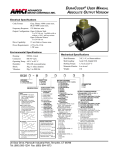
A D V A N C E D M IC R O C O N T R O L S DURACODER® USER MANUAL ANALOG OUTPUT VERSION IN C . Electrical Specifications Output Precision: 12 bit analog voltage or current Power up settling time: 20 mSec max. Voltage Configuration: 0 to 5Vdc, 0 to 10Vdc, ±5Vdc, ±10Vdc, -5 to 0Vdc, -10 to 0Vdc Current Configuration: 4 to 20mA, 0 to 20mA, 0 to 24mA Voltage Load Capacity: 2KΩ min. Current Load Capacity: Vin ≤15Vdc: 420 Ω max. Vin = 24Vdc: 800Ω max. Power Requirements: 4.75 to 26.4Vdc 1.5W max. Environmental Specifications Housing: Connector: Operating Temp: Humidity: Shock: Vibration: D C 2 5 1 = 0 .3 7 5 " D ia . 2 = 1 0 m m D ia . S E A L N o te s : 1 ) L e v e l U p d a te - T h e o u tp u ts c o n tin u o u s ly u p d a te w h e n a lo g ic '1 ' v o lt a g e is s u p p lie d to th e in p u t p in . p d a o n ly d to a tra te - T h w h e n th e in p n s itio n 3 ) M x - M u ltip le x o O u tp u ts a re p a th e in p u t p in is A llo w s m u ltip le o n s in g le in p u t e o u tp u ts th e v o lta g e u t p in . p tio n . s s iv e w h e n p u lle d to G N D . D u ra C o d e rs w ir e s . ) G a t e d Z - Z P u ls e is a c tiv e fo r 1 /2 C y c le o f B . A B D U R A C O D E R T Y P E S T A N D A R D P R O D U C T A = A b s o lu te P a r a lle l L e v e l U p d a te 1 N = In c r e m e n ta l, G a te d V = A n a lo g V o lta g e C = A n a lo g C u r r e n t S = A b s o lu te S e r ia l D a ta A L S O A V A IL A B L E B = A b s o lu te P a r a lle l E d g e U p d a te 2 L = A b s o lu te P a r a lle l L e v e l U p d a te 1, M x 3 E = A b s o lu te P a r a lle l E d g e U p d a te 2, M x 3 M = In c r e m e n ta l, U n g a te d S in g le E n d e d o u tp u t o n ly . M A T IN G Z ) U n g a t e d Z - Z P u ls e is a c tiv e fo r 1 C y c le o f A . B Z O U T P U T S C A L IN G IF D 1 2 3 4 5 6 7 8 B D G IF P 0 IF 1 2 C O N N E C T O R S : 3 A ll m a tin g c o n n e c to r s a r e n o w o r d e r e d a s s e p e r a te lin e ite m s . A ll A b s o lu te D u r a C o d e r s ...................................... M S -1 9 A 3/8" or 10mm stainless Axial 15 lb, radial 30 lb 1.5 oz.in. @ 25° C 4 oz-in-sec2 1 lb S H A F T D IA . F = S q u a r e F la n g e S = 2 .5 " D ia . S e r v o M o u n t B E A R IN G Shaft Diameter: Shaft Loading: Starting Torque: Moment of Inertia: Weight: B H O U S IN G 2 ) E d g e U u p d a te s u p p lie m a k e s Mechanical Specifications NEMA 4 rated MS "R" style -40° C to 85° C 98% RH, noncondensing 50g, 11 mSec duration 20g, 5 to 2000 Hz A ll A n a lo g D u r a C o d e r s ................................... M S D -1 0 A ll In c r e m e n ta l D u r a C o d e r s w /o D iffe r e n tia l O u tp u t . M S - 1 6 In c re m e n ta l D u ra C o d e rs w / D iffe r e n tia l O u tp u t ..... M S D - 1 0 4 IF 5 1 IF 2 6 3 2 1 3 U R A C O D E R T Y = 1 ,0 2 4 G ra y C o d e = 1 ,0 2 4 N a tu r a l B in a = 4 ,0 9 6 G ra y C o d e = 4 ,0 9 6 N a tu r a l B in a = 3 6 0 B C D = 1 0 0 0 B C D = 3 6 0 0 B C D = P r o g r a m m a b le R e s o lu tio n a n d O u 0 0 0 2 to B 4 0 9 6 F a c to r y S e t B in a r y 0 0 0 2 to D 4 0 0 0 F a c to ry S e t B C D 0 0 0 2 to G 4 0 9 6 F a c to ry S e t G ra y D U R A C O D E R T Y R G M - F ie ld P r o g r a m 0 0 2 to 1 0 2 4 - F a c to ry D U R A C O D E R T Y = 0 to 5 V d c = 0 to 1 0 V d c = ± 5 V d c = ± 1 0 V d c = -5 to 0 V d c = -1 0 to 0 V d c D U R A C O D E R T Y = 4 to 2 0 m A = 0 to 2 0 m A = 0 to 2 4 m A D U R A C O D E R T Y = C A N = D e v ic e N e t = S D S P E = A ,B ,E ,L C O N N E C T O R S = S id e E = E n d ry ry O U T P U T C O N F IG U R A T IO N tp u t C o d e P E = M , N m a b le S e t P E = V IF D H IG A = B = C = L O F G H IF A B D P E = C E IF P E = S 20 Gear Drive, Plymouth Industrial Park, Terryville, CT 06786-2408 Tel: (860) 585-1254 Fax: (860) 584-1973 N M L K C U R A C O D E R T Y P E = A , B , E , H T R U E O U T P U T S C u r r e n t S o u r c e , S in g le E n d e d , 2 4 V C u r r e n t S in k , S in g le E n d e d , 2 4 V d c C u r r e n t S in k , S in g le E n d e d , w ith 1 0 K W P u ll U p R e s is to r . W T R U E O U T P U T S = C u r r e n t S o u r c e , S in g le E n d e d , 2 4 V = C u r r e n t S in k , S in g le E n d e d , 2 4 V d c = C u r r e n t S in k , S in g le E n d e d , w ith 1 0 K W P u ll U p R e s is to r . D U R A C O D E R T Y P E = M , N = C u r r e n t S o u r c e , S in g le E n d e d , 2 4 V = C u r r e n t S in k , S in g le E n d e d , 2 4 V d c = C u r r e n t S in k , S in g le E n d e d , w ith 2 .2 K W P u ll U p R e s is to r . = D iffe r e n tia l L in e D r iv e r 5 V d c O u tp u t O n ly . N o t a v a ila b le w ith D u r a C o d e r T y p e = C u r r e n t S o u r c e , S in g le E n d e d , w ith 2 .2 K W P u ll D o w n R e s is to r . D U R A C O D E R T Y P E = V , C = 3 6 0 ° O u tp u t S ig n a l P e r io d = 1 8 0 ° O u tp u t S ig n a l P e r io d = 9 0 ° O u tp u t S ig n a l P e r io d = 4 5 ° O u tp u t S ig n a l P e r io d L d c M a x . M a x . d c M a x . M a x . d c M a x . M a x . M . Outline Drawings and Connector Pinout 0 .8 8 " T o ta l c le a r a n c e n e e d e d fo r m a tin g ( ) = D im e n s io n s in m illim e te r s 2 .5 0 " (6 3 .5 ) 0 .3 0 0 " (7 .6 2 ) (2 2 .4 ) m a o f 3 .5 "(8 re m o v a l c o n n e c to x . Output Connector MS3102E18-1P 9 ) o f r. S H A F T D IA . S E E N O T E 1 A H D C 2 5 A n a lo g 2 .3 1 " S e r v o M o u n t E n d C o n n e c t o r (5 8 .6 4 ) I G 0 .9 0 0 " (2 2 .8 6 ) 0 .8 5 0 " (2 1 .5 9 ) 0 .1 0 " (2 .5 ) # 8 - 3 2 U N F - 2 B . 0 .1 8 " ( 4 .6 ) m in d e p th . S ix p la c e s , 6 0 ° a p a r t o n a 1 .8 7 5 " ( 4 7 .6 3 ) B .C . ( ) = D im e n s io n s in m illim e te r s 1 .3 5 " (3 4 .3 ) m T o ta l c le a r a n n e e d e d fo r re m a tin g c o n n e M S 3 1 0 2 E 1 8 -1 P C o n n e c to r 0 .1 0 " (2 .5 ) 3 .0 0 " (7 6 .2 ) m a x . (3 6 .3 ) 0 .3 0 0 " (7 .6 2 ) 2 .8 7 " (7 2 .9 ) m a x . PIN NO. 1 .4 3 " s q . a x . c e o f 3 .5 "(8 9 ) m o v a l o f c to r. M S 3 1 0 2 E 1 8 -1 P C o n n e c to r 0 .3 0 0 " (7 .6 2 ) S H A F T D IA . S E E N O T E 1 D C 2 5 A n a lo g 2 .3 1 " # 8 -3 2 U 0 .1 8 " (4 S ix p la c o n 1 .8 7 1 .2 5 0 " (3 1 .7 5 ) 1 .2 4 9 " (3 1 .7 2 ) CL 1 .0 3 2 " 0 .9 0 0 " (2 2 .8 6 ) 0 .8 5 0 " (2 1 .5 9 ) N F -2 B . .6 ) m in . d e p th . e s , 6 0 ° a p a rt 5 " (4 7 .6 2 ) B .C . ty p . 0 .3 0 0 " (7 .6 2 ) S H A F T D IA . S E E N O T E 1 1 .0 3 2 " (2 6 .2 1 ) CL ty p . 2 .6 5 " 0 .9 0 0 " (2 2 .8 6 ) 0 .8 5 0 " (2 1 .5 9 ) 2 .5 0 " (6 3 .5 ) d ia . 2 .6 5 " ( ) = D im e n s io n s in m illim e te r s NO CONNECTION B NO CONNECTION C +DC INPUT D DIR CONTROL E DC RETURN F ANALOG OUTPUT G NO CONNECTION H CASE GROUND I DC RETURN J NO CONNECTION 0 .8 8 " T o ta l c le a r a n c e n e e d e d fo r m a tin g (2 2 .4 ) m a o f 3 .5 "(8 re m o v a l c o n n e c to Pin D: Dir Control - This pin controls which direction the shaft must turn to increment the position data. With this pin open circuit, position data increases with CCW rotation (looking at the shaft). Connecting this pin to Pin I, (DC Return), forces the position to increase with CW rotation (looking at the shaft). x . 9 ) o f r. D C 2 5 A n a lo g NOTES: .2 5 0 " (6 .3 5 ) M S 3 1 0 2 E 1 8 -1 P C o n n e c to r 2 .9 5 " (7 4 .9 ) m a x . 1) This pin should never be connected to Pin C (+DC Input). 2 .8 7 " (7 2 .9 ) m a x . (3 6 .3 ) a x . c e o f 3 .5 "(8 9 ) m o v a l o f c to r. M S 3 1 0 2 E 1 8 -1 P C o n n e c to r 0 .3 0 0 " (7 .6 2 ) 2 .6 5 " (6 7 .3 ) CL S H A F T D IA . S E E N O T E 1 D C 2 5 A n a lo g 1 .2 5 0 " (3 1 .7 5 ) 1 .2 4 9 " (3 1 .7 2 ) 1 .0 3 2 " F la n g e M o u n t S id e C o n n e c to r (2 6 .2 1 ) ty p . 1 .0 3 2 " (2 6 .2 1 ) CL 2 .6 5 " (6 7 .3 ) 2) Connection to Pin I (DC Return) must be done at the DC25 Connector. Do not connect at the other end of the cable. 1 .4 3 " s q . 1 .3 5 " (3 4 .3 ) m T o ta l c le a r a n n e e d e d fo r re m a tin g c o n n e ty p . 0 .2 1 8 " (5 .5 4 ) d ia . F o u r p la c e s 0 .9 0 0 " (2 2 .8 6 ) 0 .8 5 0 " (2 1 .5 9 ) FUNCTION A ( ) = D im e n s io n s in m illim e te r s (6 7 .3 ) D 0 .1 0 " (2 .5 ) 0 .1 0 " (2 .5 ) F la n g e M o u n t E n d C o n n e c t o r (6 7 .3 ) 1 .2 5 0 " (3 1 .7 5 ) 1 .2 4 9 " (3 1 .7 2 ) (6 3 .5 ) 2 .7 0 " (6 8 .6 ) m a x . 0 .2 1 8 " (5 .5 4 ) d ia . F o u r p la c e s . (2 6 .2 1 ) 2 .5 0 " F la n g e M o u n t S id e C o n n e c to r (5 8 .6 ) C J F E 1 .2 5 0 " (3 1 .7 5 ) 1 .2 4 9 " (3 1 .7 2 ) B .2 5 0 " (6 .3 5 ) 2 .6 5 " (6 7 .3 ) m a x . 2 .5 0 " (6 3 .5 ) N O T E 1 If S h M If S h M If S h M a ft a x . a ft a x . a ft a x . D ia D ia D ia D ia D ia D ia m e . = m e . = m e . = te 0 te 9 te 0 r .3 r .9 r .2 D ig 7 4 7 D ig 9 3 m D ig 4 9 7 it = ", it = m it = ", 1 : M in 2 : , M 3 : M in (0 . D (1 in . (0 . D .3 ia 0 D .2 ia 7 5 " N o m in a . = 0 .3 7 4 4 " m m N o m in a ia . = 9 .9 8 5 m 5 0 " N o m in a . = 0 .2 4 9 2 " l) l) m l) Output Load Calculations Voltage Output DuraCoder: A voltage output DuraCoder can drive an output load of 2 KΩ or greater. Current Output DuraCoder: The maximum load that can be driven by a current output DuraCoder depends upon the power supply voltage applied to +DC Input (Pin C). For input voltages up to 15Vdc the maximum load is 420Ω. For input voltages above 15Vdc the maximum load is: RLOADMAX = (+DC Input - 5) Maximum Output Current Maximum Output Current = 0.020A or 0.024A Wiring Diagram 5 1 POWER SUPPLY 2 SHIELD +Vdc -Vdc GND INPUT DEVICE CHASSIS GND -IN +IN 3 A H I G B J F E BLK RED RED BLK C D BLK BLK WHT WHT 6 7 4 BELDEN 9729 CABLE 1) 2) 3) 4) 5) 6) 7) Connector Type: MS3016A18-1S (AMCI Part# MSD-10). Use two, twisted, individually shielded pairs. Cable Type Belden 9729 or equivalent such as Manhattan M39249. The DuraCoder case must be connected to Earth Ground. This is usually accomplished through its mounting. If not properly grounded through its mounting, a wire from PIN H must be connected to an Earth Ground point as close as possible to the DuraCoder. Do Not connect PIN H to the cable shields. This can form a ground loop that may affect the operation of the DuraCoder. Units are shipped for CCW increasing output. (Looking at shaft.) For CW increasing output, Jumper PIN D to PIN I at the connector. Use a regulated power supply with voltage output in the range of 7 to 24Vdc. If cable length is less than 30 feet, a power supply of 5 to 24Vdc can be used. For DuraCoder type DCx-xxVxxxx (Voltage Output) the input device impedence must be greater than 2KΩ. If the input device impedence exceeds 10KΩ, consider installing a 10KΩ resistor in parallel with the input terminals. PIN E and PIN I are internally connected for DuraCoder S/N 24094 and above. For S/N below 24094 connect PIN E to PIN I at the DuraCoder connector. DO NOT connect or disconnect the DuraCoder from its MS connector while power is applied. Under limited circumstances, damage to the DuraCoder may result. Important User Information The products and application data described in this manual are useful in a wide variety of different applications. Therefore, the user and others responsible for applying these products described herein are responsible for determining the acceptability for each application. While efforts have been made to provide accurate information within this manual, AMCI assumes no responsibility for the application or the completeness of the information contained herein. UNDER NO CIRCUMSTANCES WILLADVANCED MICRO CONTROLS, INC. BE RESPONSIBLE OR LIABLE FORANY DAMAGES OR LOSSES, INCLUDING INDIRECT OR CONSEQUENTIAL DAMAGES OR LOSSES,ARISING FROMTHE USE OFANY INFORMATION CONTAINEDWITHIN THIS MANUAL, ORTHE USE OFANY PRODUCTS OR SERVICES REFERENCED HEREIN. No patent liability is assumed by AMCI, with respect to use of information, circuits, equipment, or software described in this manual. The information contained within this manual is subject to change without notice. ® DuraCoder is a registered trademark of AMCI. AMCI is a registered trademark, and the AMCI logo is a trademark of Advanced Micro Controls, Inc. Standard Warranty ADVANCED MICRO CONTROLS, INC. warrants that all equipment manufactured by it will be free from defects, under normal use, in materials and workmanship for a period of eighteen months. Within this warranty period, AMCI shall, at its option, repair or replace, free of charge, any equipment covered by this warranty which is returned, shipping charges prepaid, within eighteen months from date of invoice, and which upon examination proves to be defective in material or workmanship and not caused by accident, misuse, neglect, alteration, improper installation or improper testing. The provisions of the “STANDARD WARRANTY” are the sole obligations of AMCI and excludes all other warranties expressed or implied. In no event shall AMCI be liable for incidental or consequential damages or for delay in performance of this warranty. Returns Policy All equipment being returned to AMCI for repair or replacement, regardless of warranty status, must have a Return Merchandise Authorization number issued byAMCI. Call (860) 585-1254 with the model number and serial number (if applicable) along with a description of the problem. A “RMA” number will be issued. Equipment must be shipped to AMCI with transportation charges prepaid. Title and risk of loss or damage remains with the customer until shipment is received by AMCI. 24 Hour Technical Support 24 Hour technical support is available on this product. If you have internet access, start at our website, www.amci.com. Product documentation and FAQ’s are available on the site that answer most common questions. If you require additional technical support, call (860) 583-7271. Your call will be answered by the factory during regular business hours, Monday through Friday, 8AM - 5PM EST. During non-business hours an automated system will ask you to enter the telephone number you can be reached at. Please remember to include your area code. The system will page an engineer on call. Please have your product model number and a description of the problem ready before you call. Revision History This manual, 940-0D023 replaces 940-0D022 Its first issue date was 04/05/2005. It improves the outline drawings, updates warranty information, and includes website tech support information. AMCI manuals are constantly evolving entities. If you notice any errors or would like to comment on the contents of this manual please call or faxAMCI Technical Documentation. Tel. (860) 585-1254 Fax. (860) 584-1973 AMCI – Leaders in Advanced Control Products