1
To our customers,
Old Company Name in Catalogs and Other Documents
On April 1st, 2010, NEC Electronics Corporation merged with Renesas Technology
Corporation, and Renesas Electronics Corporation took over all the business of both
companies. Therefore, although the old company name remains in this document, it is a valid
Renesas Electronics document. We appreciate your understanding.
Renesas Electronics website: http://www.renesas.com
April 1st, 2010
Renesas Electronics Corporation
Issued by: Renesas Electronics Corporation (http://www.renesas.com)
Send any inquiries to http://www.renesas.com/inquiry.
Notice
1.
2.
3.
4.
5.
6.
7.
All information included in this document is current as of the date this document is issued. Such information, however, is
subject to change without any prior notice. Before purchasing or using any Renesas Electronics products listed herein, please
confirm the latest product information with a Renesas Electronics sales office. Also, please pay regular and careful attention to
additional and different information to be disclosed by Renesas Electronics such as that disclosed through our website.
Renesas Electronics does not assume any liability for infringement of patents, copyrights, or other intellectual property rights
of third parties by or arising from the use of Renesas Electronics products or technical information described in this document.
No license, express, implied or otherwise, is granted hereby under any patents, copyrights or other intellectual property rights
of Renesas Electronics or others.
You should not alter, modify, copy, or otherwise misappropriate any Renesas Electronics product, whether in whole or in part.
Descriptions of circuits, software and other related information in this document are provided only to illustrate the operation of
semiconductor products and application examples. You are fully responsible for the incorporation of these circuits, software,
and information in the design of your equipment. Renesas Electronics assumes no responsibility for any losses incurred by
you or third parties arising from the use of these circuits, software, or information.
When exporting the products or technology described in this document, you should comply with the applicable export control
laws and regulations and follow the procedures required by such laws and regulations. You should not use Renesas
Electronics products or the technology described in this document for any purpose relating to military applications or use by
the military, including but not limited to the development of weapons of mass destruction. Renesas Electronics products and
technology may not be used for or incorporated into any products or systems whose manufacture, use, or sale is prohibited
under any applicable domestic or foreign laws or regulations.
Renesas Electronics has used reasonable care in preparing the information included in this document, but Renesas Electronics
does not warrant that such information is error free. Renesas Electronics assumes no liability whatsoever for any damages
incurred by you resulting from errors in or omissions from the information included herein.
Renesas Electronics products are classified according to the following three quality grades: “Standard”, “High Quality”, and
“Specific”. The recommended applications for each Renesas Electronics product depends on the product’s quality grade, as
indicated below. You must check the quality grade of each Renesas Electronics product before using it in a particular
application. You may not use any Renesas Electronics product for any application categorized as “Specific” without the prior
written consent of Renesas Electronics. Further, you may not use any Renesas Electronics product for any application for
which it is not intended without the prior written consent of Renesas Electronics. Renesas Electronics shall not be in any way
liable for any damages or losses incurred by you or third parties arising from the use of any Renesas Electronics product for an
application categorized as “Specific” or for which the product is not intended where you have failed to obtain the prior written
consent of Renesas Electronics. The quality grade of each Renesas Electronics product is “Standard” unless otherwise
expressly specified in a Renesas Electronics data sheets or data books, etc.
“Standard”:
8.
9.
10.
11.
12.
Computers; office equipment; communications equipment; test and measurement equipment; audio and visual
equipment; home electronic appliances; machine tools; personal electronic equipment; and industrial robots.
“High Quality”: Transportation equipment (automobiles, trains, ships, etc.); traffic control systems; anti-disaster systems; anticrime systems; safety equipment; and medical equipment not specifically designed for life support.
“Specific”:
Aircraft; aerospace equipment; submersible repeaters; nuclear reactor control systems; medical equipment or
systems for life support (e.g. artificial life support devices or systems), surgical implantations, or healthcare
intervention (e.g. excision, etc.), and any other applications or purposes that pose a direct threat to human life.
You should use the Renesas Electronics products described in this document within the range specified by Renesas Electronics,
especially with respect to the maximum rating, operating supply voltage range, movement power voltage range, heat radiation
characteristics, installation and other product characteristics. Renesas Electronics shall have no liability for malfunctions or
damages arising out of the use of Renesas Electronics products beyond such specified ranges.
Although Renesas Electronics endeavors to improve the quality and reliability of its products, semiconductor products have
specific characteristics such as the occurrence of failure at a certain rate and malfunctions under certain use conditions. Further,
Renesas Electronics products are not subject to radiation resistance design. Please be sure to implement safety measures to
guard them against the possibility of physical injury, and injury or damage caused by fire in the event of the failure of a
Renesas Electronics product, such as safety design for hardware and software including but not limited to redundancy, fire
control and malfunction prevention, appropriate treatment for aging degradation or any other appropriate measures. Because
the evaluation of microcomputer software alone is very difficult, please evaluate the safety of the final products or system
manufactured by you.
Please contact a Renesas Electronics sales office for details as to environmental matters such as the environmental
compatibility of each Renesas Electronics product. Please use Renesas Electronics products in compliance with all applicable
laws and regulations that regulate the inclusion or use of controlled substances, including without limitation, the EU RoHS
Directive. Renesas Electronics assumes no liability for damages or losses occurring as a result of your noncompliance with
applicable laws and regulations.
This document may not be reproduced or duplicated, in any form, in whole or in part, without prior written consent of Renesas
Electronics.
Please contact a Renesas Electronics sales office if you have any questions regarding the information contained in this
document or Renesas Electronics products, or if you have any other inquiries.
(Note 1) “Renesas Electronics” as used in this document means Renesas Electronics Corporation and also includes its majorityowned subsidiaries.
(Note 2) “Renesas Electronics product(s)” means any product developed or manufactured by or for Renesas Electronics.
User’s Manual
RX78K0R Ver. 4.10
Real-Time Operating System
Task Debugger
Target Tool
Task Debugger Ver.4.10 for RX78K0R
Document No. U18454EJ2V0UM00 (2nd edition)
Date Published August 2007
© NEC Electronics Corporation 2007
Printed in Japan
[MEMO]
2
User’s Manual U18454EJ2V0UM
Windows is either registered trademarks or trademarks of Microsoft Corporation in the United States
and/or other countries.
Pentium is a trademark of Intel Corporation.
User’s Manual U18454EJ2V0UM
3
• The information in this document is current as of August, 2007. The information is subject to
change without notice. For actual design-in, refer to the latest publications of NEC Electronics data
sheets or data books, etc., for the most up-to-date specifications of NEC Electronics products. Not
all products and/or types are available in every country. Please check with an NEC Electronics sales
representative for availability and additional information.
• No part of this document may be copied or reproduced in any form or by any means without the prior
written consent of NEC Electronics. NEC Electronics assumes no responsibility for any errors that may
appear in this document.
• NEC Electronics does not assume any liability for infringement of patents, copyrights or other intellectual property
rights of third parties by or arising from the use of NEC Electronics products listed in this document or any
other liability arising from the use of such products. No license, express, implied or otherwise, is granted under
any patents, copyrights or other intellectual property rights of NEC Electronics or others.
• Descriptions of circuits, software and other related information in this document are provided for illustrative
purposes in semiconductor product operation and application examples. The incorporation of these
circuits, software and information in the design of a customer's equipment shall be done under the full
responsibility of the customer. NEC Electronics assumes no responsibility for any losses incurred by
customers or third parties arising from the use of these circuits, software and information.
• While NEC Electronics endeavors to enhance the quality, reliability and safety of NEC Electronics products,
customers agree and acknowledge that the possibility of defects thereof cannot be eliminated entirely. To
minimize risks of damage to property or injury (including death) to persons arising from defects in NEC
Electronics products, customers must incorporate sufficient safety measures in their design, such as
redundancy, fire-containment and anti-failure features.
• NEC Electronics products are classified into the following three quality grades: "Standard", "Special" and
"Specific".
The "Specific" quality grade applies only to NEC Electronics products developed based on a
customer-designated "quality assurance program" for a specific application. The recommended applications of
an NEC Electronics product depend on its quality grade, as indicated below. Customers must check the quality
grade of each NEC Electronics product before using it in a particular application.
"Standard": Computers, office equipment, communications equipment, test and measurement equipment, audio
and visual equipment, home electronic appliances, machine tools, personal electronic equipment
and industrial robots.
"Special": Transportation equipment (automobiles, trains, ships, etc.), traffic control systems, anti-disaster
systems, anti-crime systems, safety equipment and medical equipment (not specifically designed
for life support).
"Specific": Aircraft, aerospace equipment, submersible repeaters, nuclear reactor control systems, life
support systems and medical equipment for life support, etc.
The quality grade of NEC Electronics products is "Standard" unless otherwise expressly specified in NEC
Electronics data sheets or data books, etc. If customers wish to use NEC Electronics products in applications
not intended by NEC Electronics, they must contact an NEC Electronics sales representative in advance to
determine NEC Electronics' willingness to support a given application.
(Note)
(1) "NEC Electronics" as used in this statement means NEC Electronics Corporation and also includes its
majority-owned subsidiaries.
(2) "NEC Electronics products" means any product developed or manufactured by or for NEC Electronics (as
defined above).
M8E 02. 11-1
4
User’s Manual U18454EJ2V0UM
[MEMO]
User’s Manual U18454EJ2V0UM
5
INTRODUCTION
Readers
This manual is intended for users who design and develop application systems using
78K0R microcontrollers products.
Purpose
This manual is intended for users to understand the functions of the Task debugger
Ver.4.10 for RX78K0R described the organization listed below.
Organization
This manual consists of the following major sections.
• General
• Installation
• Starting and exiting
• Window reference
• Real-time OS trace function
• Error messages
How to read this manual
It is assumed that the readers of this manual have general knowledge in the fields of
electrical engineering, logic circuits, microcontrollers, C language, and assemblers.
To understand the hardware functions of the 78K0R microcontrollers
→ Refer to the User’s Manual of each product.
To understand the instruction functions of the 78K0R microcontrollers
→ Refer to 78K0R Microcontrollers Instructions User's Manual (U17792E).
Conventions
Data significance:
Higher digits on the left and lower digits on the right
Note:
Footnote for item marked with Note in the text
Caution:
Information requiring particular attention
Remark:
Supplementary information
Numerical representation: Binary...XXXX or XXXXB
Decimal...XXXX
Hexadecimal...0xXXXX
Prefixes indicating power of 2 (address space and memory capacity):
6
K (kilo)
210 = 1024
M (mega)
220 = 10242
User’s Manual U18454EJ2V0UM
Related Documents
Refer to the documents listed below when using this manual.
The related documents indicated in this publication may include preliminary versions.
However, preliminary versions are not marked as such.
Documents related to development tools (User’s Manuals)
Document Name
CC78K0R C Compiler
Document No.
Operation
U17838E
Language
U17837E
Operation
U17836E
Language
U17835E
SM+ System Simulator
Operation
U18010E
RX78K0R Real-Time Operating System
Functionalities
U18317E
Internal Structure
U18318E
Task Debugger
This document
RA78K0R Assembler Package
AZ78K0R System Performance Analyzer
U18802E
PM+ Project Manager
U17990E
ID78K0R-QB Integrated Debugger
Operation
User’s Manual U18454EJ2V0UM00
U17839E
7
[MEMO]
8
User’s Manual U18454EJ2V0UM
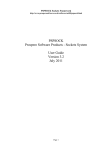
CONTENTS
CHAPTER 1 GENERAL ... 13
1. 1 Overview ... 13
1. 2 Operating Environment ... 13
CHAPTER 2 INSTALLATION ... 15
2. 1 Installing RD78K0R ... 15
2. 2 Folder Configuration ... 15
2. 3 Uninstalling RD78K0R ... 15
CHAPTER 3 STARTING AND EXITING ... 16
3. 1 Starting ... 16
3. 2 Exiting ... 17
CHAPTER 4 WINDOW REFERENCE ... 18
4. 1 Explanation of RD78K0R Window’s Each Area ... 18
4. 1. 1 Title bar ... 19
4. 1. 2 Real-time OS resource selection buttons ... 19
4. 1. 3 Real-time OS resource list display area ... 19
4. 1. 4 Detailed display area ... 19
4. 1. 5 HLD check box ... 19
4. 1. 6 Menu bar ... 20
4. 1. 7 Status bar ... 21
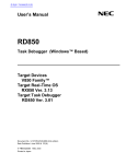
4. 2 Explanation of Display Contents ... 22
4. 2. 1 Task information display ... 22
4. 2. 2 Eventflag information display ... 25
4. 2. 3 Semaphore information display ... 27
4. 2. 4 Mailbox information display ... 28
4. 2. 5 Fixed-sized memory pool information display ... 30
4. 2. 6 Cyclic handler information display ... 32
4. 2. 7 System queue information display ... 34
4. 2. 8 System information display ... 36
CHAPTER 5 ERROR MESSAGES ... 38
5. 1 Display Format ... 38
5. 2 Error Messages ... 38
5. 3 Warning Messages ... 39
User’s Manual U18454EJ2V0UM
9
INDEX ... 40
REVISION HISTORY ... 41
10
User’s Manual U18454EJ2V0UM
LIST OF FIGURES
Figure No.
Title and Page
2-1
Folder Configuration ... 15
3-1
RD78K0R Startup Screen ... 16
4-1
Display Example of the RD78K0R Window ... 18
4-2
Example of Task Information Display ... 22
4-3
Example of Eventflag Information Display ... 25
4-4
Example of Semaphore Information Display ... 27
4-5
Example of Mailbox Information Display: 1 ... 28
4-6
Example of Mailbox Information Display: 2 ... 28
4-7
Example of Fixed-Sized Memory Pool Information Display ... 30
4-8
Example of Cyclic Handler Information Display ... 32
4-9
Example of Timer Queue Information Display ... 34
4-10
Example of Ready Queue Information Display ... 34
4-11
Example of System Information Display ... 36
5-1
Message Dialog Box ... 38
User’s Manual U18454EJ2V0UM
11
LIST OF TABLES
Table No.
Title and Page
4-1
Real-Time OS Resource Selection Buttons ... 19
4-2
Real-Time OS Resource List Display Area: Task Information ... 22
4-3
Detailed Display Area: Task Information ... 23
4-4
Statuses of Tasks ... 23
4-5
Additional Task Information ... 24
4-6
Real-Time OS Resource List Display Area: Eventflag Information ... 25
4-7
Detailed Display Area: Eventflag Information ... 26
4-8
Real-Time OS Resource List Display Area: Semaphore Information ... 27
4-9
Detailed Display Area: Semaphore Information ... 27
4-10
Real-Time OS Resource List Display Area: Mailbox Information ... 29
4-11
Detailed Display Area: Mailbox Information ... 29
4-12
Real-Time OS Resource List Display Area: Fixed-Sized Memory Pool Information ... 30
4-13
Detailed Display Area: Fixed-Sized Memory Pool Information ... 31
4-14
Real-Time OS Resource List Display Area: Cyclic Handler Information ... 32
4-15
Detailed Display Area: Cyclic Handler Information ... 33
4-16
Real-Time OS Resource List Display Area: Timer Queue Information ... 35
4-17
Real-Time OS Resource List Display Area: Ready Queue Information ... 35
4-18
Detailed Display Area: Timer Queue Information ... 35
4-19
Detailed Display Area: Ready Queue Information ... 35
4-20
Real-Time OS Resource List Display Area: System Information ... 36
4-21
Detailed Display Area: System Information ... 37
5-1
Error Message List ... 38
5-2
Warning Message List ... 39
12
User’s Manual U18454EJ2V0UM
CHAPTER 1 GENERAL
CHAPTER 1 GENERAL
1. 1 Overview
The RD78K0R (Task Debugger for RX78K0R is referred to as RD78K0R in this user’s manual) connects with a
debugger using TIP (Tool Interface Protocol), and provides Powerful debugging functions for a application program in
which the real-time OS (RX78K0R) is embedded.
The RD78K0R provides the following functions.
(1) The real-time OS resource display function
Displays the statuses of RX78K0R objects, such as tasks and semaphores, by executing a break at a certain
point of the user program running in the debugger.
*
1. 2 Operating Environment
The RD78K0R requires an environment in which a debugger supporting TIP is running.
The RD78K0R cannot be used just on its own.
(1) Hardware
- Host machine
The machine by which the target OS operates.
- In-circuit emulator
IECUBE series (from NEC Electronics)
[Caution] In-circuit emulators other than the above can be connected to the RD78K0R, as long as they
support TIP.
- On-chip debug emulator
MINICUBE2 (from NEC Electronics)
[Caution] On-chip debug emulators other than the above can be connected to the RD78K0R, as long as
they support TIP.
- Target system
Target system in which 78K0R is incorporated.
(2) Software
- OS (any of the following)
Windows® 2000 Professional, Windows XP Home Edition, Windows XP Professional
[Caution] It is recommended that the newest Service Pack be installed in any of the above OSs.
- C compiler
CC78K0R (from NEC Electronics)
- Assembler
RA78K0R (from NEC Electronics)
User’s Manual U18454EJ2V0UM
13
CHAPTER 1 GENERAL
- Real-time OS
RX78K0R (from NEC Electronics)
- Debugger
ID78K0R-QB (from NEC Electronics)
[Caution] Debuggers other than the above can be connected to the RD78K0R, as long as they support
TIP.
- Simulator
SM+ for 78K0R (from NEC Electronics)
SM+ for 78K0R/Kx3 (from NEC Electronics)
[Caution] Simulators other than the above can be connected to the RD78K0R, as long as they support
TIP.
14
User’s Manual U18454EJ2V0UM
CHAPTER 2 INSTALLATION
CHAPTER 2 INSTALLATION
2. 1 Installing RD78K0R
The RD78K0R is included with the real-time OS package (RX78K0R). When the RX78K0R is installed, the
RD78K0R can be aloso installed if necessary, as it is supplied in the same package.
For the details on how to install the RX78K0R, refer to the RX78K0R user’s manual.
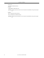
2. 2 Folder Configuration
After installing the RD78K0R, the configuration of the folders related to the RD78K0R is as follows:
Figure 2-1 Folder Configuration
<rd_root> (default: C:\Program Files\NEC Electronics Tools\RD78K0R\Vx.xx)
bin
Execution files (wishtip.exe, rd78k0r.tcl)
lib78K0R
tcl7.6
Library files for Tcl7.6
tk4.2
Library files for Tk4.2
doc
Document-related files (*.pdf/*.txt)
hlp
Help file (*.chm)
WINDOWS
[Caution]
Library files for TIP, Tcl/TK
<rd_root>: Installation folder for RD78K0R
WINDOWS: System folder for Windows
[Note] A shortcut the RD78K0R (default: [Program] -> [NEC Electronics Tools] -> [RD78K0R] -> [Vx.xx]) is automatically added to the Windows start menu.
2. 3 Uninstalling RD78K0R
For the details on how to uninstall the RD78K0R, refer to the RX78K0R user’s manual.
User’s Manual U18454EJ2V0UM
15
CHAPTER 3 STARTING AND EXITING
CHAPTER 3 STARTING AND EXITING
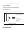
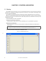
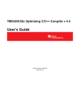
3. 1 Starting
The RD78K0R cannot be used just on its own. Since the RD78K0R operates by communicating with and obtaining
information from a debugger, the debugger must operate at the same time. For the operation of the debugger, refer to
the user’s manual of the debugger.
The RD78K0R is described using theTcl/Tk script language. Therefore, RD78K0R itself is not an execution file.
Moreover, since the RD78K0R operates while communicating with the debugger, it requires a Tcl/Tk that includes a
communication mechanism. This expanded Tcl/Tk is called wishtip (wishtip.exe). The RD78K0R is executed by being
interpreted with a wishtip.
To start the RD78K0R, use either or the following:
(1) Start from the [Start] menu of Windows
Select [Programs] -> [NEC Electronics Tools] -> [RD78K0R] -> [Vx.xx] -> [RD78K0R Vx.xx] (default).
(2) Start from the command line
Execute the following commands as a startup parameter of wishtip (if the RD78K0R was installed with the
default setting).
C:\Program Files\NEC Electronics Tools\RD78K0R\Vx.xx\bin\wishtip.exe
C:\Program Files\NEC Electronics Tools\RD78K0R\Vx.xx\bin\RD78K0R.tcl
The following window will be displayed after the RD78K0R is started.
Figure 3-1 RD78K0R Startup Screen
*
16
User’s Manual U18454EJ2V0UM
CHAPTER 3 STARTING AND EXITING
3. 2 Exiting
To exit the RD78K0R, select [File] menu -> [Quit] on the RD78K0R window.
User’s Manual U18454EJ2V0UM
17
CHAPTER 4 WINDOW REFERENCE
CHAPTER 4 WINDOW REFERENCE
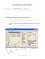
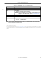
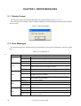
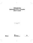
4. 1 Explanation of RD78K0R Window’s Each Area
Only the window shown below is available in the RD78K0R (multiple windows can be opened at the same time,
however).
This section explains the function details in each area.
No information is displayed in the window when the RD78K0R is started. To display object information, the user
must execute a break for the user program from the debugger and select the relevant object by using a real-time OS
resource selection button.
[Caution] The following conditions must be satisfied to display object information.
- A load module linked with the RX78K0R has been downloaded to the debugger. (The RX78K0R
including symbol information should have been loaded.)
- RX78K0R system initialization processing has been completed. (Control should have been transferred
to the task that operates first.)
Operation is not guaranteed if a real-time OS resource selection button is clicked without the above conditions being
satisfied.
Figure 4-1 Display Example of the RD78K0R Window
*
Title bar
Menu bar
Status bar
Real-time OS resource list display area
Real-time OS resource selection buttons
HLD check box
18
User’s Manual U18454EJ2V0UM
Detailed display area
CHAPTER 4 WINDOW REFERENCE
4. 1. 1 Title bar
The title bar displays the type of the object (task, event, etc.) selected by a real-time OS resource selection button, in
the following format.
*
*
- RD78K0R [Real-time OS resource Type]
4. 1. 2 Real-time OS resource selection buttons
These buttons are used to select the real-time OS resource to be displayed in the Real-time OS resource list display
area.
By clicking a button, the list of information of all the real-time OS resources generated/registered within the selected
real-time OS resource is displayed in the Real-time OS resource list display area.
Table 4-1 Real-Time OS Resource Selection Buttons
Button
Function
[TSK]
Displays task information.
[EVF]
Displays eventflag information.
[SEM]
Displays semaphore information.
[MBX]
Displays mailbox information.
[MPF]
Displays fixed-sized memory pool information.
[CYC]
Displays cyclic handler information.
[QUE]
Displays system queue (timer queue or ready queue) information.
[SBT]
Displays system information.
[Caution] The selected object cannot be switched by clicking these buttons during application program execution.
Clicking of these buttons is valid only when application programs are in the break state.
*
4. 1. 3 Real-time OS resource list display area
For the object selected by the Real-time OS resource selection buttons, all the object information items that have been
generated and registered are listed in the object ID order. ("NONE" is displayed if no relevant objects exist.)
For details on the contents of this area, refer to "4. 2 Explanation of Display Contents".
4. 1. 4 Detailed display area
This area displays the detailed information of a real-time OS resource selected with the Real-time OS resource list
display area.
For details on the contents of this area, refer to "4. 2 Explanation of Display Contents".
4. 1. 5 HLD check box
This check box is used to fix the status (hold status) currently displayed.
When this check box is checked, the display information is not updated until the check box is unchecked, regardless
of whether program execution or breaks occur thereafter. This check box is not checked in the default condition.
By using this function, statuses at different times can easily be compared by starting up several RD78K0R.
User’s Manual U18454EJ2V0UM
19
CHAPTER 4 WINDOW REFERENCE
4. 1. 6 Menu bar
(1) [File] menu
[Report]
Outputs all kinds of object information to a text file (*.txt). [Note]
[Quit]
Terminates the RD78K0R.
[Note] The output file name can be specified freely in the Report to dialog box opened automatically at this time.
(The name consists of the current yy/mm/dd and time is set by default.)
The object information output here reflects the current object state, which has been sent from the
debugger, regardless of selection of the HLD check box.
(2) [View] menu
*
[Task]
Displays task information.
[Eventflag]
Displays eventflag information.
[Semaphore]
Displays semaphore information.
[Mailbox]
Displays mailbox information.
[Fixed-sized memorypool]
Displays fixed-sized memory pool information.
[Cyclic handler]
Displays cyclic handler information.
[System queue]
Displays system queue (timer queue or ready queue) information.
[System base table]
Displays system information.
(3) [Help] menu
20
[Contents]
Opens the help file for the RD78K0R.
[About RD78K0R]
Displays the version information of the RD78K0R.
User’s Manual U18454EJ2V0UM
CHAPTER 4 WINDOW REFERENCE
4. 1. 7 Status bar
The appearance of the status bar varies as follows, according to the RX78K0R status when receiving object
information sent from the debugger.
[Normal state]
*
When processing of the user-coded application program (task, interrupt handler, cyclic handler, idle routine) is in
progress.
[Real-time OS execution state]
When processing of an RX78K0R service call or a timer handler is in progress.
[Caution] Invalid object information may be displayed in the real-time OS execution state.
User’s Manual U18454EJ2V0UM
21
CHAPTER 4 WINDOW REFERENCE
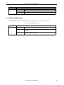
4. 2 Explanation of Display Contents
This section is described the contents of the real-time OS resource information selected with the Real-time OS
resource selection buttons.
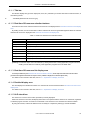
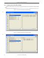
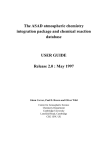
4. 2. 1 Task information display
Task information items are displayed in the ID order by clicking the [TSK] button.
The following contents are displayed in the Real-time OS resource list display area and the Detailed display area.
Figure 4-2 Example of Task Information Display
*
Table 4-2 Real-Time OS Resource List Display Area: Task Information
[Format] 1st item : [ 2nd item, 3rd item, 4th item]
1st Item
ID
22
2nd Item
Task name
3rd Item
Current priority
User’s Manual U18454EJ2V0UM
4th Item
Current state
(refer to Table 4-4)
CHAPTER 4 WINDOW REFERENCE
Table 4-3 Detailed Display Area: Task Information
Item
Contents
Name
Task name
TaskID
ID
Entry
Start address
File name # Line number (Symbol name) [Note]
[Caution] The task source can be opened in the Source Window of the debugger
by double-clicking this line. Refer to "Task source display".
Status
Current state (refer to Table 4-4)
Pri
Current priority (initial priority)
suscnt
Suspension count
wupcnt
Wakeup request count
actcnt
Activation request count
pc
Current PC
File name # Line number (Symbol name) [Note]
[Caution] The task source can be opened in the Source Window of the debugger
by double-clicking this line. Refer to "Task source display".
stkptr
Task stack pointer (current task stack pointer - initial task stack pointer)
[Caution] The task stack can be opened in the Memory Window of the debugger
by double-clicking this line. Refer to "Task stack display".
exinf
Extended information
atr
Attribute (initial interrupt status/initial activation status)
[Task initial interrupt status]
TA_ENAINT: Maskable interrupt acknowledgment enabled.
TA_DISINT:
Maskable interrupt acknowledgment disabled.
[Task initial activation status]
TA_ACT:
Task is activated after the creation.
Stack Data
When a task has been executed and the stack area is in use, the stack contents
from the initial stack pointer to the current stack pointer are displayed in 16-bit
widths.
[Note] A symbol of startup address is displayed as a symbol, but if symbol information does not exist, startup
address is displayed in hexadecimal notation.
Task statuses of the tasks are as follows:
Table 4-4 Statuses of Tasks
Status
Description
TTS_RUN
RUNNING state
TTS_RDY
READY state
TTS_WAI
WAITING state
TTS_SUS
SUSPENDED state
TTS_WAS
WAITING-SUSPENDED state
TTS_DMT
DORMANT state
User’s Manual U18454EJ2V0UM
23
CHAPTER 4 WINDOW REFERENCE
If TTS_WAI or TTS_WAS is displayed as a task status, the wait cause is displayed as additional information.
Table 4-5 Additional Task Information
Status
*
Description
TTW_SLP
Sleeping state
TTW_DLY
Delayed state
TTW_FLG
Waiting state for an eventflag
TTW_SEM
Waiting state for a semaphore
TTW_MBX
Waiting state for a mailbox
TTW_MPF
Waiting state for a fixed-sized memory pool
- Task source display
By double-clicking the [Entry] line in the Detailed display area, the task source can be opened in the Source
Window of the debugger, and by double-clicking the [pc] line, the task source at the pc location can be opened, if
there is the debug information.
The Assembler Window of the debugger can be opened if there is no debug information.
- Task stack display
The contents of the memory area pointed to by a task stack pointer can be displayed in the Memory window of the
debugger by double-clicking the [stkptr] line in the Detailed display area.
24
User’s Manual U18454EJ2V0UM
CHAPTER 4 WINDOW REFERENCE
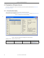
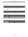
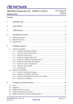
4. 2. 2 Eventflag information display
Event flag information items are displayed in the ID order by clicking the [EVF] button.
The following contents are displayed in the Real-time OS resource list display area and the Detailed display area.
Figure 4-3 Example of Eventflag Information Display
*
Table 4-6 Real-Time OS Resource List Display Area: Eventflag Information
[Format] 1st item : [ 2nd item, 3rd item, 4th item]
1st Item
ID
2nd Item
Eventflag name
3rd Item
Existence of wait task
TSK:
NON:
4th Item
Current bit pattern
Wait task
No wait task
User’s Manual U18454EJ2V0UM
25
CHAPTER 4 WINDOW REFERENCE
Table 4-7 Detailed Display Area: Eventflag Information
Item
Contents
Name
Eventflag name
EvfID
ID
atr
Attribute (Queuing method/number of queued tasks/bit pattern clear
[Queuing method of task]
TA_WSGL:
Only one task is allowed to be in the waiting state for the eventflag.
[Number of queued tasks]
TA_TFIFO:
Task wait queue is in FIFO order.
[Bit pattern clear]
TA_CLR:
Bit pattern is cleared when a task is released from the waiting
state for that eventflag.
pattern
Current bit pattern
wait tsk
This item is displayed when a task waiting for an eventflag exists.
Name
Wait task name
ID
Wait task ID
ptn
Wait bit pattern
wfmode
Wait mode
TWF_ANDW:
TTWF_ORW:
26
User’s Manual U18454EJ2V0UM
AND waiting condition
OR waiting condition
CHAPTER 4 WINDOW REFERENCE
4. 2. 3 Semaphore information display
Semaphore information items are displayed in the ID order by clicking the [SEM] button.
The following contents are displayed in the Real-time OS resource list display area and the Detailed display area.
Figure 4-4 Example of Semaphore Information Display
*
Table 4-8 Real-Time OS Resource List Display Area: Semaphore Information
[Format] 1st item : [ 2nd item, 3rd item, 4th item]
1st Item
ID
2nd Item
Semaphore name
3rd Item
Existence of wait task
TSK:
NON:
4th Item
Current resource count
Wait task
No wait task
Table 4-9 Detailed Display Area: Semaphore Information
Item
Contents
Name
Semaphore name
SemID
ID
Count
Current resource count
IniCnt
Initial resource count
wait tsk
This item is displayed when a task waiting for a semaphore exists.
Name
Wait task name
ID
Wait task ID
User’s Manual U18454EJ2V0UM
27
CHAPTER 4 WINDOW REFERENCE
4. 2. 4 Mailbox information display
Mailbox information items are displayed in the ID order by clicking the [MBX] button.
The following contents are displayed in the Real-time OS resource list display area and the Detailed display area.
Figure 4-5 Example of Mailbox Information Display: 1
*
Figure 4-6 Example of Mailbox Information Display: 2
*
28
User’s Manual U18454EJ2V0UM
CHAPTER 4 WINDOW REFERENCE
Table 4-10 Real-Time OS Resource List Display Area: Mailbox Information
[Format] 1st item : [ 2nd item, 3rd item, 4th item]
1st Item
ID
2nd Item
Mailbox name
3rd Item
Existence of wait task/
message
TSK:
MSG:
NON:
4th Item
Queuing method of task
(refer to Table 4-11)
Wait task
Wait message
No wait task/
message
Table 4-11 Detailed Display Area: Mailbox Information
Item
Contents
Name
Mailbox name
MbxID
ID
tskopt
Queuing method of task [Note]
TA_TFIFO:
msgopt
Queuing method of message
TA_MFIFO:
TA_MPRI:
Task
Message
Task wait queue is in FIFO order.
Message queue is in FIFO order.
Message queue is in message priority order.
This item is displayed when a task waiting for a message exists.
Name
Wait task name
ID
Wait task ID
This item is displayed when a message exists.
msgadr
Message address
[Caution] The memory list can be opened in the
Memory Window of the debugger by
double-clicking this line. Refer to "Message
memory display".
[Note] In the RX78K0R, task queuing information is fixed to the FIFO order.
- Message memory display
The Memmory Window of the debugger can be opened by double-clicking the [msgadr] line within the [Message]
item in the Detailed display area.
User’s Manual U18454EJ2V0UM
29
CHAPTER 4 WINDOW REFERENCE
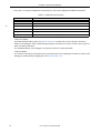
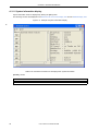
4. 2. 5 Fixed-sized memory pool information display
Fixed-sized memory pool information items are displayed in the ID order by clicking the [MPF] button.
The following contents are displayed in the Real-time OS resource list display area and the Detailed display area.
Figure 4-7 Example of Fixed-Sized Memory Pool Information Display
*
Table 4-12 Real-Time OS Resource List Display Area: Fixed-Sized Memory Pool Information
[Format] 1st item : [ 2nd item, 3rd item]
1st Item
ID
2nd Item
Fixed-sized memory pool name
3rd Item
Existence of wait task
TSK:
NON:
30
User’s Manual U18454EJ2V0UM
Wait task
No wait task
CHAPTER 4 WINDOW REFERENCE
Table 4-13 Detailed Display Area: Fixed-Sized Memory Pool Information
Item
Contents
Name
Fixed-sized memory pool name
MpfID
ID
size
Memory block size (in bytes)
inicnt
Total number of memory blocks
free
Number of free memory blocks
wait task
This item is displayed when a task waiting for a memory block exists.
Use Blocks
Name
Wait task name
ID
Wait task ID
This item is displayed when a memory block currently being used exists.
mpfadr
Start address of the memory block currently being
used.
User’s Manual U18454EJ2V0UM
31
CHAPTER 4 WINDOW REFERENCE
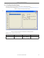
4. 2. 6 Cyclic handler information display
Cyclic handler information items are displayed in the cyclic handler ID order by clicking the [CYC] button.
The following contents are displayed in the Real-time OS resource list display area and the Detailed display area.
Figure 4-8 Example of Cyclic Handler Information Display
*
Table 4-14 Real-Time OS Resource List Display Area: Cyclic Handler Information
[Format] 1st item : [ 2nd item, 3rd item]
1st Item
ID
32
2nd Item
Cyclic handler name
User’s Manual U18454EJ2V0UM
3rd Item
Current state (refer to Table 4-15)
CHAPTER 4 WINDOW REFERENCE
Table 4-15 Detailed Display Area: Cyclic Handler Information
Item
*
Contents
Name
Cyclic handler name
CycID
ID
Entry
Start address
File name # Line number (Symbol name) [Note]
[Caution] The cyclic handler source can be opened in the Source Window of the
debugger by double-clicking this line. Refer to "Cyclic handler source
display".
intvl
Activation cycle (unit: ticks)
remain
Time left before the next activation (unit: ticks)
activate
Current state
TCYC_STP:
TCYC_STA:
Non-operational state
Operational state
[Note] A symbol of startup address is displayed as a symbol, but if symbol information does not exist, startup
address is displayed in hexadecimal notation.
- Cyclic handler source display
By double-clicking the [Entry] line in the Detailed display area, the Source Window of the debugger can be opened
if there is debug information, and the Assembler WIndow of the debugger can be opened if there is no debug information.
User’s Manual U18454EJ2V0UM
33
CHAPTER 4 WINDOW REFERENCE
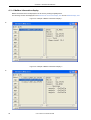
4. 2. 7 System queue information display
As system queue information, timer queue and ready queue information items are displayed by clicking the [QUE]
button.
The following contents are displayed in the Real-time OS resource list display area and the Detailed display area.
Figure 4-9 Example of Timer Queue Information Display
*
Figure 4-10 Example of Ready Queue Information Display
*
34
User’s Manual U18454EJ2V0UM
CHAPTER 4 WINDOW REFERENCE
Table 4-16 Real-Time OS Resource List Display Area: Timer Queue Information
[Format] 1st item
1st Item
TimerQueue
Table 4-17 Real-Time OS Resource List Display Area: Ready Queue Information
[Format] 1st item : 2nd item
1st Item
2nd Item
ReadyQueue Pri
Priority
Table 4-18 Detailed Display Area: Timer Queue Information
Item
*
Contents
clk
Wait clock count (unit: ticks)
Name
Task name/Cyclic handler name
ID
Task ID/Cyclic handler ID
Table 4-19 Detailed Display Area: Ready Queue Information
Item
task
Contents
Name
Task name
ID
Task ID
User’s Manual U18454EJ2V0UM
35
CHAPTER 4 WINDOW REFERENCE
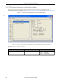
4. 2. 8 System information display
System information items are displayed by clicking the [SBT] button.
The following contents are displayed in the Real-time OS resource list display area and the Detailed display area.
Figure 4-11 Example of System Information Display
*
Table 4-20 Real-Time OS Resource List Display Area: System Information
[Format] 1st item
1st Item
System Base Table
36
User’s Manual U18454EJ2V0UM
CHAPTER 4 WINDOW REFERENCE
Table 4-21 Detailed Display Area: System Information
Item
Dispatch
Contents
Dispatching state
disable:
enable:
CPU
Dispatching disabled state
Dispatching enabled state
CPU state
lock:
unlock:
SchReq
CPU locked state
CPU unlocked state
Scheduler activation request
non:
requested:
TmStatus
Timer processing execution status
busy:
not busy:
*
No request for scheduler activation
Scheduler activation requested
Timer processing execution in progress
Timer processing execution not performed
RunTask
Name of task in the RUNNING state ("non" is displayed if no relevant tasks exist.)
High-Pri
Value of the highest priority among tasks in the RUNNING state and READY state
("- -" is displayed if no relevant tasks exist).
OS Level
Real-time OS processing nest counter
in Init:
OS processing nest counter = -1
in Tasks or Idle:OS processing nest counter = 0
in OS service: OS processing nest counter > 0
HdrNstCnt
Maskable interrupt nest counter
PriMap
Priority map (binary notation of priority map)
SysStack
System stack pointer (current system stack pointer - initial system stack pointer)
[Caution] The system stack can be opened in the Memory Window of the debugger by double-clicking this line. Refer to "System stack display".
maker
Kernel maker’s code (0x117: NEC Electronics)
prid
Identification number of the kernel
spver
Version number of the ITRON Specification
prver
Version number of the kernel
prno
Management information of the kernel product
System Stack
When the system stack area is in use due to interrupt servicing, the system stack
contents from the initial stack pointer to the current stack pointer are displayed in
16-bit widths.
- System stack display
The contents of the memory area pointed to by a system stack pointer can be displayed in the Memory window of
the debugger by double-clicking the [SysStack] line in the Detailed display area.
User’s Manual U18454EJ2V0UM
37
CHAPTER 5 ERROR MESSAGES
CHAPTER 5 ERROR MESSAGES
5. 1 Display Format
The messages output by RD78K0R are displayed in the message dialog box shown in Figure 5-1.
There are two kinds of messages. When a message is displayed, a letter indicating the message type is prefixed to
the error number.
Figure 5-1 Message Dialog Box
5. 2 Error Messages
The following lists the error messages output from the RD78K0R, causes and countermeasures, in the error number
order.
Table 5-1 Error Message List
*
Error Number
1000
1100
1200
1300
1400
38
Description
Message
Not connect.
Cause
Displayed when the debugger is not connected.
Action by User
Check the connection with the debugger.
Message
Debugger running.
Cause
Object information was opened (by clicking a real-time OS resource
selection button) during user program execution.
Action by User
Display object information only when the debugger is in the break state.
Message
Maybe RX not loaded.
Cause
No RX78K0R symbol information is included in the load module, or the
RX78K0R has not been loaded.
Action by User
Check if RX78K0R symbol information is included in the load module, or
the RX78K0R has been loaded.
Message
Can not Open Helpfile.
Cause
Help file is not exist.
Action by User
Check if the help file (*.chm) exists in the configuration (see "2. 2 Folder
Configuration").
Message
Fail to write the file.
Cause
Data was not written to the specified file correctly.
Action by User
Check the available disk capacity, or the specified file attribute (if it is
read-only, or the like).
User’s Manual U18454EJ2V0UM
CHAPTER 5 ERROR MESSAGES
Error Number
1600
Description
Message
Maybe link is broken.
Cause
The queue data in the RX78K0R kernel may be broken.
Action by User
Check the RX78K0R.
5. 3 Warning Messages
The following lists the warning messages output from the RD78K0R, causes and their meanings.
Table 5-2 Warning Message List
*
Error Number
-
Description
Message
OS Running Status.
Cause
This message is output when a break is executed during real-time OS
processing.
Action by User
Since a break occurs during real-time OS processing, invalid object
information may be displayed.
User’s Manual U18454EJ2V0UM
39
INDEX
C
Cyclic handler information ... 32
D
Detailed display area ... 19
System information ... 36
System queue information ... 34
T
Task information ... 22
Tcl/Tk ... 16
The real-time OS resource display function ... 13
E
Title bar ... 19
Error messages ... 38
Eventflag information ... 25
Exiting ... 17
F
Fixed-sized memory pool information ... 30
Folder configuration ... 15
H
HLD check box ... 19
Hold status ... 19
U
Uninstalling ... 15
V
Version information ... 20
W
Warning messages ... 39
wishtip ... 16
I
Installing ... 15
M
Mailbox information ... 28
Menu bar ... 20
R
Resource list display area ... 19
Resource selection buttons ... 19
S
Semaphore information ... 27
Starting ... 16
Status bar ... 21
40
User’s Manual U18454EJ2V0UM
REVISION HISTORY
The following table shows the revision history up to this edition. Page numbers in the “Applied to:” column indicate
the pages of this edition in which the revision was applied.
The mark
* shows major revised points in this edition.
Applied to:
-
Description
1.1 Overview
Deletion of "(2) The real-time OS trace function".
-
1.2 Operating Environment
Modification of description.
p.16
3.1 Starting
Figure 3-1 RD78K0R Startup Screen
Modification of GUI image diagram.
-
CHAPTER 4 WINDOW REFERENCE
Figure 4-1 to Figure 4-11
Modification of GUI image diagram.
p.19
4.1.1 Title bar
Modification of description.
[Before change]
RD78K0R [Resource Type]
[After change]
RD78K0R [Real-time OS resource type]
p.19
4.1.2
Modification of title.
[Before change]
Resource selection buttons
[After change]
Real-time OS resource selection buttons
p.19
4.1.3
Modification of title.
[Before change]
Resource list display area
[After change]
Real-time OS resource list display area
User’s Manual U18454EJ2V0UM
41
Applied to:
-
Description
4.1.5 RTOS trace buttons
Deletion of this item.
p.20
4.1.6 Menu bar
(2) [View] menu
Modification of description.
[Before change]
Fixed-size memorypool
[After change]
Fixed-sized memorypool
-
4.1.6 Menu bar
Deletion of "(3) [Trace] menu".
p.21
4.1.7 Status bar
[Normal state]
Modification of description.
[Before change]
... of the user-coded application program is ...
[After change]
... of the user-coded application program (task, interrupt handler, cyclic handler, idle routine) is ...
p.24
4.2.1 Task information display
Table 4-5 Additional Task Information
Modification of description.
[Before change]
TTW_EVF
[After change]
TTW_FLG
p.33
4.2.6 Cyclic handler information display
Table 4-15 Detailed Display Area: Cyclic Handler Information
Modification of description.
[Before change]
ID
[After change]
CycID
p.35
4.2.7 System queue information display
Table 4-18 Detailed Display Area: Timer Queue Information
clk
Modification of description.
[Before change]
Wait clock count
42
User’s Manual U18454EJ2V0UM
Applied to:
Description
[After change]
Wait clock count (unit: ticks)
-
CHAPTER 5 REAL-TIME OS TRACE FUNCTION
Deletion of this chapter.
p.38
5.2 Error Messages
Table 5-1 Error Message List
Modification of description.
[Before change]
Number
[After change]
Error Number
-
5.2 Error Messages
Table 5-1 Error Message List
Deletion of descriptions regarding error numbers 2000, 2100 and 2200.
p.39
5.3 Warning Messages
Table 5-2 Warning Message List
Unification of table format with that of "Table 5-1".
User’s Manual U18454EJ2V0UM
43
For further information,
please contact:
NEC Electronics Corporation
1753, Shimonumabe, Nakahara-ku,
Kawasaki, Kanagawa 211-8668,
Japan
Tel: 044-435-5111
http://www.necel.com/
[America]
[Europe]
[Asia & Oceania]
NEC Electronics America, Inc.
2880 Scott Blvd.
Santa Clara, CA 95050-2554, U.S.A.
Tel: 408-588-6000
800-366-9782
http://www.am.necel.com/
NEC Electronics (Europe) GmbH
Arcadiastrasse 10
40472 Düsseldorf, Germany
Tel: 0211-65030
http://www.eu.necel.com/
NEC Electronics (China) Co., Ltd
7th Floor, Quantum Plaza, No. 27 ZhiChunLu Haidian
District, Beijing 100083, P.R.China
Tel: 010-8235-1155
http://www.cn.necel.com/
Hanover Office
Podbielskistrasse 166 B
30177 Hannover
Tel: 0 511 33 40 2-0
Munich Office
Werner-Eckert-Strasse 9
81829 München
Tel: 0 89 92 10 03-0
Stuttgart Office
Industriestrasse 3
70565 Stuttgart
Tel: 0 711 99 01 0-0
United Kingdom Branch
Cygnus House, Sunrise Parkway
Linford Wood, Milton Keynes
MK14 6NP, U.K.
Tel: 01908-691-133
Succursale Française
9, rue Paul Dautier, B.P. 52
78142 Velizy-Villacoublay Cédex
France
Tel: 01-3067-5800
Sucursal en España
Juan Esplandiu, 15
28007 Madrid, Spain
Tel: 091-504-2787
Tyskland Filial
Täby Centrum
Entrance S (7th floor)
18322 Täby, Sweden
Tel: 08 638 72 00
Filiale Italiana
Via Fabio Filzi, 25/A
20124 Milano, Italy
Tel: 02-667541
Shanghai Branch
Room 2509-2510, Bank of China Tower,
200 Yincheng Road Central,
Pudong New Area, Shanghai, P.R.China P.C:200120
Tel:021-5888-5400
http://www.cn.necel.com/
Shenzhen Branch
Unit 01, 39/F, Excellence Times Square Building,
No. 4068 Yi Tian Road, Futian District, Shenzhen,
P.R.China P.C:518048
Tel:0755-8282-9800
http://www.cn.necel.com/
NEC Electronics Hong Kong Ltd.
Unit 1601-1613, 16/F., Tower 2, Grand Century Place,
193 Prince Edward Road West, Mongkok, Kowloon, Hong Kong
Tel: 2886-9318
http://www.hk.necel.com/
NEC Electronics Taiwan Ltd.
7F, No. 363 Fu Shing North Road
Taipei, Taiwan, R. O. C.
Tel: 02-8175-9600
http://www.tw.necel.com/
NEC Electronics Singapore Pte. Ltd.
238A Thomson Road,
#12-08 Novena Square,
Singapore 307684
Tel: 6253-8311
http://www.sg.necel.com/
NEC Electronics Korea Ltd.
11F., Samik Lavied’or Bldg., 720-2,
Yeoksam-Dong, Kangnam-Ku,
Seoul, 135-080, Korea
Tel: 02-558-3737
http://www.kr.necel.com/
Branch The Netherlands
Steijgerweg 6
5616 HS Eindhoven
The Netherlands
Tel: 040 265 40 10
G0706