1
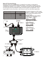
Basic RF System Design
Knowing how much amplification is needed for a system is essential to
designing a successful RF distribution system. This section explains how to
calculate the losses in your system. You should provide enough amplification
to overcome all of the insertion losses of all the system components. If the
signal splits into two branches, each branch must be calculated separately.
Typical Insertion Loss
~5.0dB
3.5dB
5.5dB
7.5dB
9.0dB
11.0dB
15.5dB
System Component
100ft. of RG6
HS-2 (2-way Splitter)
HS-3 (3-way Splitter)
HS-4 (4-way Splitter)
HS-6 (6-way Splitter)
HS-8 (8-way Splitter)
HS-16 (16-way Splitter)
Antenna
or CATV
+10dBmV
4-Way Branch:
Main: +21.5dBmV
HS-4: -7.5dB
+14.5dB
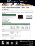
CVT-15WB
6-Way Branch:
Main: +21.5dBmV
HS-6: -9.0dB
+11.5dB
RF INPUT
DC12V
INPUT
C HANNEL V ISION
Example: Assume a CATV input
signal of 10dBmV. Next, calculate
all the gains and losses of the
components.
Primary Branch Calculation:
CATV Input: 10dBmV
CVT-15WB: +15dB
HS-2:
-3.5dB
Main total: +21.5dBmV
TM
CVT-15WB
CATV Forward Path (54-860MHz):+15dB
CATV Return Path (5-42MHz): Passive
WideBand CATV Path (975-1525MHz):Passive
OUT+POWER
+25dBmV
IN/out
5MHz-1GHz All Port DC passing
Part No. HS-2
2-WAY SPLITTER/COMBINER
C HANNEL V ISION
TM
OUT/in
+21.5dBmV
IN/out
OUT/in
OUT/in
5MHz-1GHz All Port DC passing
Part No. HS-4
4-WAY SPLITTER/COMBINER
CHANNEL VISION
OUT/in
TM
OUT/in
+14.5dBmV
OUT
OUT
OUT
C H A N N E L V I S I O N Part No. HS-6
TM
IN
6
OUT/in
+21.5dBmV
OUT
6-WAY SPLITTER 5MHz-1GHz
All ports DC passing
OUT
OUT
+11.5dBmV