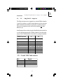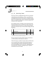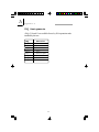
1
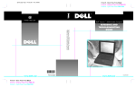
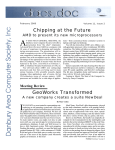
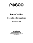
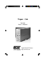
Tiger Cub
System
User’s Manual
Light Industrial Products...
http://www.itox.com
Copyright
This publication contains information that is protected by copyright.
No part of it may be reproduced in any form or by any means or used
to make any transformation/adaptation without the prior written permission from the copyright holders.
This publication is provided for informational purposes only. The
manufacturer makes no representations or warranties with respect to
the contents or use of this manual and specifically disclaims any express or implied warranties of merchantability or fitness for any particular purpose. The user will assume the entire risk of the use or the
results of the use of this document. Further, the manufacturer reserves
the right to revise this publication and make changes to its contents at
any time, without obligation to notify any person or entity of such
revisions or changes.
All Rights Reserved.
Trademarks
Microsoft® MS-DOS® is a registered trademark of Microsoft Corporation. IBM is a registered trademark of International Business Machine Corporation. AMD and Élan are registered trademarks of Advanced Micro Devices, Inc. DiskOnChip is a registered trademark of
M-systems Inc.. Datalight ROM-DOS® is a registered trademark of
Datalight, Inc.. DR-DOS® is a registered trademark of Caldera. Other
trademarks and registered trademarks of products appearing in this
manual are the properties of their respective holders.
Caution:
Danger of explosion if battery incorrectly replaced. Replace only with
the same or equivalent type recommended by the manufacturer. Dispose of used batteries according to the battery manufacturer’s instructions.
1
1
Tiger Cub User’s Manual
FCC and DOC Statement on Class B
This equipment has been tested and found to comply with the lim-
its for a Class B digital device, pursuant to Part 15 of the FCC
rules. These limits are designed to provide reasonable protection
against harmful interference when the equipment is operated in a
residential installation. This equipment generates, uses and can radiate radio frequency energy and, if not installed and used in accordance with the instruction manual, may cause harmful interference to radio communications. However, there is no guarantee
that interference will not occur in a particular installation. If this
equipment does cause harmful interference to radio or television
reception, which can be determined by turning the equipment off
and on, the user is encouraged to try to correct the interference
by one or more of the following measures:
•
•
•
•
Reorient or relocate the receiving antenna.
Increase the separation between the equipment and the receiver.
Connect the equipment into an outlet on a circuit different
from that to which the receiver is connected.
Consult the dealer or an experienced radio TV technician for
help.
Notice:
1. The changes or modifications not expressly approved by the
party responsible for compliance could void the user's authority to operate the equipment.
2. Shielded interface cables must be used in order to comply with
the emission limits.
ITOX, Inc.
8 Elkins Road
East Brunswick, NJ 08816
U.S.A.
(732) 390-2815
http://www.itox.com
DFI Computers Ltd.
Unit 1, Kangley BusinessCentre
Kangley Bridge Road
London, UK SE6 5AQ
(44-181)776-5555
http://dfiuk.demon.co.uk
DFI-USA
135 Main Avenue
Sacramento, CA 95838
U.S.A.
(916) 568-1234
http://www.dfiusa.com
DFI Inc.
100 Huan-Ho St.
Hsi-Chih Town
Taipei Haien, Taiwan R.O.C.
(886-2) 2694-2986
http://dfiweb.com
2
DFI Germany
Varreler Landstrabe 6
28816 Stuhr
Germany
(49-421) 565-6811
http://[email protected]
Introduction
Table of Contents
Chapter 1 - Introduction
Tiger Cub System Concept .........................................
Specfications..............................................................
System Configuration...................................................
Package Checklist.......................................................
8
8
10
11
Chapter 2 - Hardware Installation and Setup
Removing the Access Cover........................................ 14
Installing Expansion Cards............................................ 14
Installing Disk Drives..................................................... 15
Wall Mounting the Tiger Cub........................................ 16
Front View ................................................................. 18
Back View ................................................................. 19
Chapter 3 - Power up Sequence
Booting DOS and Running MTEZ and INTERLNK.............. 22
Chapter 4 - General Software BIOS Setup Utility
The Basic Input/Output System...................................... 26
Standard CMOS Setup.................................................. 26
Custom Configuration................................................... 30
Shadow Configuration................................................... 31
Standard Diagnosticc Routines...................................... 32
Reset CMOS To Last Known Values.................................. 33
Reset CMOS To Factory Defaults.................................... 33
Write To CMOS and Exit................................................. 33
Exit Without Changing CMOS.......................................... 33
Chapter 5 - File/Software Loading
Running INTERSERV and INTERLNK................................... 36
3
1
Appendix A - Board Layout
Connector/Jumper Setting Locations & Functions..
J1, J2 - DRQ/DACK Jumpers.......................................
J5 - Local LED Indicators.............................................
J6, J8 - Watchdog Timer .............................
J12 - Enable COM1 IRQ .......................................
J13 - General Purpose Input/Output Connector............
IRQ Assignements...................................................
System Board Connector Layout..................................
40
41
41
42
43
43
44
45
Appendix B - Software Utilities
ITOXBLIN.COM............................................................
ITOXLED.OBJ...............................................................
ITOXSCR.COM............................................................
BOOT.COM................................................................
Software Control of Watchdog Timer...........................
48
49
49
49
50
Appendix C - Troubleshooting
Frequently Asked Questions......................................... 54
Appendix D - Warranty
Warranty Terms.......................................................... 58
Appendix E - Year 2000 Compliance
Year 2000 Statement................................................
62
Index....................................................................
63
5
6
CHAPTER
1
Introduction
7
1
Tiger Cub User’s Manual
Features and Specifications
Introduction
Tiger Cub System Concept
The ITOX Tiger Cub uses state-of-the-art design to provide a compact,
low cost PC platform for Computer Telephony and industrial applications
that require multiple, full length ISA interface cards.
The Tiger Cub is designed for unattended operation in light industrial
environments. It is packaged in a small industrial enclosure that can be
mounted on a wall or placed on a shelf or table. It is designed for turnkey
systems that utilize auto-executing DOS application programs. Consequently, there is no need for a keyboard, mouse, video display or floppy
disk in operational systems, and the most reliable, cost effective solution
is achieved by not providing these items.
One of the Tiger Cub serial ports can be used to control the Tiger Cub
during application development, diagnostic testing and for loading
programs onto the Tiger Cub’s hard disk. An on-board watchdog timer
supports reliable operation in unattended applications by restarting the
system automatically if the software hangs-up.
Specifications
The Tiger Cub’s processor and memory chips are soldered in place on the
motherboard. Consequently, the processor speed and memory size must
be specified at the time of order.
ITOX-EAR Motherboard
Processor
AMD Élan enhanced AM486 single chip
Microcontroller
Available speeds – 33, 66 or 100 MHz
(Factory configured)
Cache
8 Kbyte unified, write-back
8
Introduction
RAM
4 Mbyte, 60 ns standard,
8 Mbyte available on special order
Watchdog Timer
Standard
Real-Time Clock
Standard, with Sony CR2032 battery or
equivalent
Disk Controller
IDE controller: supports two drives up to 8GB
each
Two sockets for Disk-on-Chip flash memory
based disks
Expansion Slots
3 full-length, full-height , 16 bit ISA
Hold down bracket provided with case
Input/Output Ports
Parallel printer port, EPP/EPC compatible
2 serial ports, 16650 UART compatible
4 line general purpose I/O, TTL level
Board Size
13.1” (337 mm) x 3.9” (96 mm)
BIOS
General Software Embedded
BIOS Ver.4 for AMD Élan
Chassis
Components
Power Supply
100 to 240 VAC switch selectable, 50/60 Hz
90 watts, with internal cooling fan and
ATX connector
Fan
Motherboard/expansion slot area cooled by
8 cm fan with air filter, 14 CFM
Disk Bays
3 disk drive bays, 3.5” (one
externally accessible)
All disks mount in removable drive tray.
9
1
1
Tiger Cub User’s Manual
Weight
12.1 pounds(5.5 kgs) [not including disk drives]
Size
15.5” (394 mm) x 5.25”(133mm) x 10.5”(266 mm)
Operating Temperature
0 to 45 C (32 to 113 F)
Humidity
10% to 90% relative humidity, Non condensing
Options
DC input power supply
System Configuration
The basic Tiger Cub is configured with a 33 MHz processor and 4 MB of
RAM memory. Higher speed processors and/or 8 MB of RAM are
available as factory installed options.
Several disk storage options are available and are not included in the basic
configuration. Available options include 24 MB Disk-on-Chip Flash disk
and 3 ½” hard drives of various capacities.
The Disk-on-Chip may be configured as the first (boot) drive or the last
drive. The Tiger Cub’s internal IDE disk controller will support one primary
drive and one slave drive.
The flash disk chips mount in sockets provided on the motherboard. Hard
drives are mounted in a removable disk tray for easy assembly. The
removable disk tray feature also allows field application software upgrades
to be performed by shipping the user a preloaded hard drive mounted in a
spare disk tray.
Floppy drives are not typically used with the Tiger Cub. However, applications requiring a floppy drive can be accommodated by installing a 3 ½”
floppy drive in the externally accessible drive bay and installing a floppy
drive controller card in one of the Tiger Cub’s ISA expansion slots.
The Tiger Cub is supplied with the Datalight ROM-DOS 6.22 operating
system in the basic configuration. Optionally available operating systems
include Microsoft MS DOS 6.22, IBM PC DOS 7.0, and Caldera DR-DOS.
10
Introduction
The Tiger Cub is designed to allow console redirection through the serial
port (COM1) for loading software and local control/debugging of application programs. This is accomplished by connecting COM1 of the Tiger
Cub to the serial port of a notebook computer or other device with a null
modem cable. The appropriate procedures are provided in Chapter 3
and Chapter 5 of this manual.
Package
Checklist
The Tiger Cub system package contains the following items:
•
•
•
•
•
One Tiger Cub complete with motherboard and power supply
One Power Cable
One floppy disk with the following software
• MTEZ terminal emulation software
• BOOT.COM
• ITOXBLIN.COM
• ITOXSCR.COM
One set of operating system software
One Manual
Optional items such as disk drives may also be enclosed in the
package. Check your packing list carefully.
If any of these items are missing or damaged, please contact your
supplier for assistance.
11
1
12
CHAPTER
2
Hardware Installation
and
Setup
13
2
Tiger Cub User’s Manual
II. Hardware Installation and Set Up
Caution: Always unplug the AC power cord from the Tiger Cub before
opening the cabinet to prevent possible contact with the rotating fan
blade or hazardous voltage. The Tiger Cub is designed so that all high
voltage components remain enclosed in the lower portion of the cabinet
when the access panel is removed. However, contact with potentially
hazardous voltage is possible if tools or screws enter the lower portion
of the case through the cable or cooling holes.
Set Input Voltage Selector Switch
The Tiger Cub is equipped with a dual range power supply for operation
with AC input voltage from 100 to 240 VAC at 50/60 Mz. Set the AC
voltage selector switch on the rear panel of the Tiger Cub to the appropriate postion based table below.
AC Voltage Switch Settings
Normal Input Voltage
Switch Setting
100-120 Vac
200-240 Vac
115
230
Removing the Access Cover
Remove the six screws on the side of the Tiger Cub cabinet (five on one
side & one on the other side) and remove the access cover to install
expansion cards and set jumpers. The Tiger Cub is supplied with a
retaining bracket to hold expansion cards in place. Remove the screw at
each end of the bracket and remove the bracket to provide access for
installing expansion cards.
Installing Expansion Cards
Warning: Electrostatic discharge (ESD) can damage your
processor, disk drives, add-in boards, and other components.
Perform the instruction procedures described at an ESD
workstation only. If such a station is not available, you
can provide some ESD protection by wearing an antistatic
wrist strap and attaching it to a metal part of the system
14
Hardware Installation and Setup
chassis. If a wrist strap is unavailable, establish and maintain
contact with the system chassis throughout any procedures
requiring ESD protection.
The Tiger Cub is designed to accept three full length, full height expansion cards utilizing the 16 bit ISA interface standard. Remove the appropriate number of filler plates from the back of the unit, install the cards in
the normal manner, and secure them in place with the screw previously
used to hold the filler plate in place.
The retaining bracket should be replaced after the cards have been
installed. Then the black plastic pads supplied with the unit should be
installed in the square holes in the bracket and positioned with the edge
of the expansion card in the “V” groove of the pad. Install the screws
supplied with the pads into the bracket so that they press on the pads at
an angle to hold the expansion cards firmly in place. The access cover
should be replaced after the jumpers have been set. See appendix A for
the correct jumper setting for your system configuration.
Installing Disk Drives
The Tiger Cub uses a removable disk tray for quick and easy mounting of
hard (and floppy) disk drives. Disks ordered from ITOX at the same time
as the Tiger Cub will be pre-loaded with the appropriate software and preinstalled in the unit. This procedure should be followed for disks not
installed by ITOX.
1. Pre-load your software onto the hard drive.
The hard drive must be loaded with the operating system including the
appropriate file loading utilities identified in Chapter 5 (not required if the
Tiger Cub has a floppy drive). Most users will find it convenient to preload all software required for the application at the same time.
2. Remove the drive tray from the front panel of the Tiger Cub.
It is not necessary to remove the access cover to install disk drives.
Verify that the Tiger Cub power cord is disconnected from the AC
voltage source. Remove the two phillips head screws located closest to
the outside edges of the lower portion of the front panel. Then
slide the drive tray out the front of the unit.
15
2
2
Tiger Cub User’s Manual
3. Install the drive(s) in the drive tray.
The drive tray includes slots for mounting up to three 3 ½ “ disk drives.
Select the set of slots you want to use and mount the drive according to
the manufacturer’s instructions. The center drive position has a knockout section that can be removed to provide exterior access to the drive.
This position is typically reserved for floppy drives. Remove the knockout before installing any of the drives if a floppy drive will be installed.
4. Connect the data and power cables.
Reach into the lower portion of the Tiger Cub case through the opening
where the drive tray mounts. Gently guide the power cable and ribbontype data cable through the opening so they can be connected to the disk
drive. The connectors are keyed for proper attachment; make sure that the
connectors are attached to the drive in the proper orientation.
5. Install the drive tray back into the Tiger Cub case.
Slide the drive tray back into the case; guide the cables into the opening
while doing this to keep them away from any sharp edges and insure they
remain fully engaged. Secure the drive tray in place with the two screws
removed in step 2 above.
6. Specify the correct hard disk type in the BIOS setup.
Complete any other hardware installation procedures before power is
applied to the unit. Enter the correct hard drive type (from disk manufacturer’s instructions) in the Basic CMOS Configuration section of the BIOS
setup (see Chapter 4).
Wall Mounting the Tiger Cub
The Tiger Cub is designed to be placed on a shelf, table or other flat
surface, or wall mounted. Rubber feet are provided for table top operation.
Four key-hole shaped mounting holes are provided in the side of the
Tiger Cub for wall mounting. Use of all four wall mounting points is
recommended and will result in the most secure installation; at least one
of the front brackets and one of the rear brackets must be used to provide
adequate support. A template for installing the mounting screws in the
wall is provided in the Tiger Cub box.
The Tiger Cub mountings have a protective back plate that prevents
narrow objects from entering the case. The mounting holes are designed
to slip over the heads of screws mounted in the wall or other vertical
16
Hardware Installation and Setup
surface upon which the Tiger Cub is to be mounted. The holes are
designed for ¼ inch (6 mm) pan head screws, but can be used with any
screws with a head diameter between 0.35 inch (9 mm) and 0.55 inch (14
mm) and a maximum head height of 0.2 inch (5 mm). The screws should be
installed to allow a clearance of 1/16 inch (1.5 mm) under the screw head
to provide clearance for the thickness of the mounting bracket.
Once the screws are installed in the wall to the proper depth, place the
Tiger Cub mounting holes over the screw heads and then slide the Tiger
Cub down to secure it in place. It can be removed for servicing by sliding
the unit up and lifting the unit off the screw heads.
17
2
2
Tiger Cub User’s Manual
Front View of Tiger Cub System
Connectors, Switches and Indicators
Air Filter Access Screws
Power LED
(Green)
Console Redirection
Switch
Yellow LED
Green LED
Red LED
Power Switch
HD Active LED
(Yellow)
18
Hardware Installation and Setup
Back View of Tiger Cub System
Connectors, Switches and Ports
COM1
Port
Parallel Port
(LPT1)
COM2
AC Voltage
Selection Switch
Power Cord
Connector
19
Port
2
20
CHAPTER
3
Power
Up
21
Sequence
3
Tiger Cub User’s Manual
Power
Up
Sequence
A notebook (or desktop) computer will be needed for setting up
the Tiger Cub’s BIOS and loading software.
The console redirection feature of the Tiger Cub will be used to
enable the notebook to serve as the keyboard and display of the
Tiger Cub.
We recommend that you boot DOS directly from the DOS disk
provided rather than running a Windows DOS box.
The floppy disk provided with the system contains the following
programs:
ITOXSCR.COM
BOOT.COM
ITOXBLN.COM
MTEZ
INTERLNK.EXE*
MTEZ must run on the notebook/PC from the floppy drive to
enact the console redirection.
1) Start with both the notebook PC & the Tiger Cub turned off.
2) Plug one end of the null modem cable into the COM1 port on
the Tiger Cub system (see chapter 2 ). The other end of the
cable will be inserted into the serial port of your notebook/PC.
3) Turn on your notebook/PC.
* When purchased with MS DOS or IBM PC-DOS program. With Datalight ROM-DOS program will
be REMDISK.EXE. With Caldera DR-DOS program will be FILELINK.EXE.
22
Power Up Sequence
4) Boot DOS from the supplied disk and run MTEZ.
cd MTEZ
A:\MTEZ>
A:\MTEZ>MTEZ (press enter)
The Main Menu screen will appear.
Main Menu Screen
Alt-Z Help
OffLine FDX CR
MTEZ by WordPerfect Corp
Dial ExpFax Redial Hangup File Change Shell Quit Terminal More
Dial a Phone Number {Alt-D}
or 1st Letter to Select
to Execute Esc to Exit Menu
After seeing this screen select ESCAPE to clear the MTEZ
menu box (below).
Dial ExpFax Redial Hangup File Change Shell Quit Terminal More
Dial a Phone Number {Alt-D}
or 1st Letter to Select
to Execute Esc to Exit Menu
5) Now turn the Power switch located on the front of the Tiger
Cub to the ON position.
The MTEZ Menu box will appear once more.
23
3
3
Tiger Cub User’s Manual
6) Select ESCAPE again.
Now you have exited MTEZ and have control of the Tiger Cub.
The keyboard and display of the notebook now act as the
keyboard and display of the Tiger Cub.
You may enter CMOS as described in chapter 4 or run your
programs.
If you need to reboot the Tiger Cub at any time:
Type BOOT while in DOS when the keyboard and
display are directed to Tiger Cub.
BOOT.COM must be installed on the Tiger Cub’s hard
drive to accomplish this task.
Use the following procedure to redirect the
keyboard and display back to the notebook PC.
1) Press Alt +Tab
The main MTEZ menu will reappear.
2) Select SHELL
The keyboard and display can now be used to control the
notebook.
3) Type EXIT (return) and then press Escape
to redirect the keyboard and display back to the Tiger Cub.
24
CHAPTER
4
BIOS Setup Utility
25
4
Tiger Cub User’s Manual
The Basic Input/Output System
The Basic Input/Output System (BIOS) is a program that takes care
of the basic level of communication between the processor and
peripherals. This chapter explains the Setup Utility for the General
Software BIOS.
After you power up your system and connect a console device as
described in chapter 3, the BIOS message appears on your screen
and you will see the memory count begin. After the memory test,
the following message will appear on the screen:
Press DEL or Control C to enter setup
System Bios Setup - Utility v4.000
(C) 1996-7 General Software, Inc. All rights reserved
--------------------------------------------------------------------------
>Basic CMOS Configuration
Custom Configuration
Shadow Configuration
Standard Diagnostic Routines
Reset CMOS to last known values
Reset CMOS to factory defaults
Write to CMOS and Exit
Exit without changing CMOS
——--—————————————————————---——
<Esc> to continue (no save)
Standard CMOS Setup
Navigation
Use the arrow keys to highlight “Basic CMOS Configuration”
and press <Enter>. A screen similar to the one on the next page
will appear.
26
BIOS Setup Utility
System Bios Setup - Basic CMOS Configuration
(C) 1996-7 General Software, Inc. All rights reserved
----------------------------------------------------------------------------------------------Base Memory
:>640
Date (month day year) : Mar 25, 1998
Extended Memory : 7168
Time (hours:min:sec) : 16 : 59 : 06
Drive A: type
: Not installed -------------------------------------------------------Drive B: type
: Not installed Cyln Heads WPcom LZone Sect Size
Hard disk C: type : 49 = AUTOCONFIG, LBA GEOMETRY
Hard disk D: type : Not installed
----------------------------------------------------------------------------------------------: Disabled
1st Boot Device
: Drive C:
Seek Floppy at Boot
: Enabled
2nd Boot Device
: (None)
Seek Hard Drive at Boot
3rd Boot Device
: (None)
System Configuration Box : Enabled
: Enabled
4th Boot Device
: (None)
Display “Hit <Del>...”
: Enabled
Primary Display
: MONO/None
Wait For F1 on Error
: Disabled
Typematic Keys
: (Unused)
NumLock State at Boot
: (Unused)
Typematic Delay
: (Unused)
Memory Parity Check
: Disabled
Typematic Rate
: (Unused)
Exhaustive Memory Test
Memory Test Tick : Enabled
Test Above 1 MB : Enabled
----------------------------------------------------------------------------------------------^E/^X/<Tab> to select or +/- to modify
The settings on the screen are for reference only. Your version may
not be identical to this one.
Date
The date format is <day>, <month>, <date>, <year>. Day displays
a day, from Sunday to Saturday. Month displays the month, from
January to December. Date displays the date, from 1 to 31. Year
displays the year.
Time
The time format is <hour>, <minute>, <second>. The time is based
on the 24-hour military-time clock. For example, 1 pm. is 13:00:00.
Hour displays hours from 00 to 23. Minute displays minutes from
00 to 59. Second displays seconds from 00 to 59.
27
4
4
Tiger Cub User’s Manual
Memory
The base memory size and extended memory size cannot be altered;
your computer automatically detects and displays them.
Base
The POST (Power On Self Test) will examine
the amount of base (or conventional) memory
installed in the system. The value of the base
memory will always be 640K.
Memory
Preset at 640
Extended Memory The BIOS examines how much extended
memory is present during the POST (Power On
Self Test). This is the amount of memory located
above 1MB in the CPU’s memory address map.
A 4MB system is preset at 3072
A 8MB system is preset at 7168
Drive A and Drive B
These categories identify the types of floppy disk drives installed.
The options for drive A and B are:
Not installed No floppy drive is installed
360K, 5-1/4 in. drive; 360KB capacity
1.2M, 5-1/4 in. AT-type high-density drive; 1.2MB
capacity
720K, 3-1/2 in.drive; 720KB capacity
1.44M, 3-1/2 in.drive; 1.44MB capacity
2.88M, 3-1/2 in.drive; 2.88MB capacity
Note:
Choosing an incorrect type might cause your system to
format the floppy disk improperly and you may not be able
to access your data.
28
BIOS Setup Utility
Hard Disk 0 and 1
The default setting will be based on the specific configuration
ordered.
Options:
1-46 PREDEFINED
47 USER TYPE
48 AUTOCONFIG, PHYSICAL GEOMETRY (system
will configure the hard drive’s value)
49 AUTOCONFIG, LBA GEOMETRY
50 AUTOCONFIG, PHOENIX CHS GEOMETRY
1ST BOOT DEVICE
Default Setting: Drive 0
2ND, 3RD, and 4TH BOOT DEVICE
Default Setting: None
Other options:
- None
- DOS IN ROM (Do NOT Select - or system will not boot)
- Drive A
PRIMARY DISPLAY
These options are only useful if you are using a video card.
Options:
MONO/NONE
AUTO
COLOR
COLOR
No monitor or monochromatic monitor
Auto selection usually 80 x 25 color
40 x 25
80 x 25
29
4
4
Tiger Cub User’s Manual
TYPEMATIC SECTION
Default setting due to no keyboard being supported.
TYPEMATIC KEYS : Unused
TYPEMATIC DELAY : Unused
TYPEMATIC RATE : Unused
MEMORY TEST TICK: Enabled is the default.
Enabled will be the standard default for all of
the following:
SEEKFLOPPYATBOOT
SEEKHARDDRIVEATBOOT
SYSTEMCONFIGURATIONBOX
DISPLAY “HIT” <DEL>...”
WAIT FOR F1 ON ERROR
Unused will appear as the default for the following
NUMLOCK STATE AT BOOT (Due to no keyboard)
MEMORY PARITY CHECK
EXHAUSTIVE MEMORY TEST: Disabled is the default
Custom Configuration
Use the arrow key to highlight “Custom Configuration” and
press <Enter>. This screen will appear.
System BIOS Setup - Custom Configuration
(C) 1996-7 General Software, Inc. All rights reserved
------------------------------------------------------------------------------Enable COM2
:>Enabled Enable LPT1
: Enabled
COM2 Base Address
: 2F8
LPT1 Base Address : 378
DMA0 Channel
:2
DMA1 Channel
:6
-------------------------------------------------------------------------------^E/^X/<Tab> to select or +/- to modify
<Esc> to return to main menu
30
BIOS Setup Utility
Enable COM2 (Options: Enabled or Disabled)
This field specifies whether the second serial port connector on the
Tiger Cub is enabled or disabled. The default setting is enabled.
COM2 Base Address (Options: 2F8 or 3F8)
This specifies the base address of the internal serial port on the
Tiger Cub. If set to 2F8 (the default setting), there will be two serial ports, if set to 3F8, there will be one serial port and the first serial
port connector will be disabled.
Enable LPT1 (Options: Enabled or Disabled)
This specifies whether the parallel port connector on the Tiger Cub
is enabled or disabled. The default setting is Enabled.
LPT1 Base Address (Options: 278 or 378)
This specifies the base address of the internal parallel port on the
Tiger Cub. The default setting is 378.
Note: The DMA channels must be selected in the BIOS to match
the jumper setting used for J1 and J2. Refer to appendix A.
DMA0 Channel (Options: 0, 2, or 3)
Select this field to access the first DMA channel. The default setting is 2. Note that DMA channel two must be selected if a floppy
drive is installed.
DMA1 Channel (Options: 5, 6, or 7)
This specifies the second DMA channel which may be accessed.
The default setting is 6.
Shadow Configuration
Shadowing is the standard feature in which ROMs are copied to
faster RAM to improve system performance.
31
4
4
Tiger Cub User’s Manual
System BIOS Setup - Shadow/Cache Configuration
(C) 1996-7 General Software, Inc. All rights reserved
------------------------------------------------------------------------------------------------Shadowing
:>Chipset
Shadow 16KB ROM at C000 : Disabled
Shadow 16KB ROM at C400 : Disabled
Shadow 16KB ROM at C800 : Disabled
Shadow 16KB ROM at CC00 : Disabled
Shadow 16KB ROM at D000 : Disabled
Shadow 16KB ROM at D400 : Disabled
Shadow 16KB ROM at D800 : Disabled
Shadow 16KB ROM at DC00 : Disabled
Shadow 16KB ROM at E000 : Enabled
Shadow 16KB ROM at E400 : Enabled
Shadow 16KB ROM at E800 : Enabled
Shadow 16KB ROM at EC00 : Enabled
Shadow 64KB ROM at F000 : Enabled
------------------------------------------------------------------------------------------------^E/^X/<Tab> to select or +/- to modify
<Esc> to return to main menu
The defaults are
Shadowing: Chipset
Shadow 16KB ROM at E400, EC00, E000, and E800 : Enabled
Shadow 64KB ROM at F000: Enabled
All other regions: Disabled
STANDARD DIAGNOSTIC ROUTINES
Select this option for testing.
This screen will appear. If you do not want to test a particular item
change enabled to disabled.
System Bios Setup - Standard Diagnostics
(C) 1996-7 General Software, Inc. All rights reserved
----------------------------------------------------------------------------------------------------CPU Core
BIOS Video Services
: Enabled
: Enabled
Floating Point Core
BIOS Block Disk Services : Enabled
: No Hdwr
Protected Mode
BIOS Serial Services
: Enabled
: Enabled
Low Memory (<1MB)
BIOS Keyboard Services : Enabled
: Enabled
Extended Memory (>1MB): Enabled
BIOS Parallel Services
: Enabled
Keyboard Controller
Video
Controller/RAM
: No Hdwr
: No Hdwr
PC/AT Keyboard
CMOS RAM & Battery : Enabled
: Disabled
----------------------------------------------------------------------------------------------------Continuous Testing
:Enabled
Tests Begin on ESC?
: Enabled
----------------------------------------------------------------------------------------------------^E/^X/<Tab> to select or +/- to modify
<Esc> to return to main menu
32
BIOS Setup Utility
RESET CMOS TO LAST KNOWN VALUES
Select this option, if while editing CMOS, you have encountered a problem. It will reset the CMOS to the values set before your edit.
RESET CMOS TO FACTORY DEFAULTS
When selected, the CMOS options will be automatically reset to the factory defaults.
WRITE TO CMOS AND EXIT
Select this option if you want the changes you made during this session
to be made to the CMOS.
After making the changes, select exit and the system will reboot.
EXIT WITHOUT CHANGING CMOS
Select if you made any chanes you do NOT want to save.. The
perivious CMOS settings will be intact.
33
4
34
CHAPTER
5
File/Software
Loading
35
5
Tiger Cub User’s Manual
File/Software Loading
Files are typically loaded onto the Tiger Cub from a notebook or
desktop PC via a null modem cable using file transfer utility
programs provided with DOS. Data is transfered at a rate of up
to 57600 bps. The Tiger Cub acts in a server capacity by
making its hard drive available to the notebook PC. The notebook PC is considered the client and can then access the drive
to load files onto it from the other drives of the notebook PC.
The appropriate file transfer programs for the available DOS
operating systems are shown below:
DOS Operating System Server Program (T. Cub) Client Program (Notebook PC)
Datalight ROM-DOS
Caldera DR-DOS
IBM PC-DOS
Microsoft MS-DOS
REMSERV.EXE
FILELINK.EXE
INTERSRV.EXE
INTERSRV.EXE
REMDISK.EXE
FILELINK.EXE
INTERLNK.EXE
INTERLNK.EXE
The appropriate operating system with the server program will
be preloaded on the Tiger Cub drive if both the operating system
and the drive were purchased from ITOX. Drives not purchased
from ITOX should be preloaded with the appropriate operating
system prior to installing them in the Tiger Cub.
The client program can be run directly from the floppy drive of
the notebook PC using the floppy disk provided with the Tiger
Cub system.
The following steps illustrate the procedure for loading software
with the MS-DOS or PC-DOS operating system located on the
floppy drive of the notebook PC. The procedure for the other
DOS operating systems is similar.
36
File/Software Loading
1) Connect the Tiger Cub and the notebook PC together with the
null modem cable, and run the MTEZ program to connect the
notebook keyboard and display to the Tiger Cub as described
in Chapter 3.
2) Change the active directory of the Tiger Cub to the DOS
directory
C:\>cd DOS (press enter)
3) Run INTERSRV on the Tiger Cub
C:\DOS>INTERSRV (press enter)
4) Move the null modem cable from COM1 to COM2 of the
Tiger Cub.
Do not turn the Tiger Cub off when moving the cable
5) The MTEZ main menu will appear again on the notebook
display screen.
Select SHELL to switch control back to the notebook.
6) Run INTERLNK. from the floppy disk.
A:\MTEZ>cd.. (press enter)
A:\>INTERLNK (press enter)
7) The hard drive of the Tiger Cub will be assigned the
designation of the next available drive in your notebook PC
(usually d: or e:) as shown in the chart on the notebook PC
screen. You can now transfer your software to the Tiger Cub by
copying it to that drive.
37
5
38
Appendix
A
ITOX-EAR
Motherboard
Layout
and
Jumpers
39
A
Appendix A
Connector Locations and Functions
The following connectors and jumper pins are provided on the ITOXEAR motherboard. Connector locations on the Tiger Cub motherboard
are shown on the figure in this appendix.
Refer to the appropriate figures in chapter two for the location of the
external connectors
CONNECTOR
FUNCTION
J1
DRQ Setting jumpers
J2
DACK Setting jumpers
J3
IDE hard disk controller
J4
Power input to motherboard, ATX type
J5
Local LED indicators
J6
Watchdog timer, reboot enable/disable
J7
Fan power, 12 Vdc
J8
Watchdog timer, blinking power LED select
J9
COM1 serial port (console redirection)
J10
COM2 serial port
J11
Parallel port
J12
Enable COM1 IRQ
J13
General Purpose I/O port
40
ITOX-EAR Motherboard Layout and Jumpers
J1, J2 – DRQ/DACK Jumpers
The Elan microprocessor supports two external DMA channels.
J1 and J2 are jumper switch locations that are used to select the
DMA channels to match those required by expansion boards.
The correct channels must be selected by jumpers and in the
BIOS set-up.
Install jumpers between the pin pairs identified in the chart below
to select the appropriate pair of DMA channels. Note that each
jumper block should not have more than two jumpers installed.
DMA Channels
0,5
0,6
0,7
2,5
2,6
2,7
3,5
3,6
3,7
J1
1-2 , 7-8
1-2, 9-10
1-2, 11-12
3-4, 7-8
3-4, 9-10
3-4, 11-12
5-6, 7-8
5-6, 9-10
5-6, 11-12
J2
1-2,
1-2,
1-2,
3-4,
3-4,
3-4,
5-6,
5-6,
5-6,
J5 – Local LED Indicators
Pin
Signal
1
2
15
16
HDD LED +
HDD LED Power LED +
Power LED -
41
7-8
9-10
11-12
7-8
9-10
11-12
7-8
9-10
11-12
A
A
Appendix A
J6, J8 - Watchdog Timer
The Tiger Cub has a watchdog timer that can be set to automatically reboot the system if it hangs up. This is very useful in unattended applications where there may not be a designated system
operator to restart the system. If you choose to use the watchdog
timer, you can enable it under software control by using the information provided in Appendix B.
The watchdog counter is essentially a preset counter that counts
down based on the system’s real time clock. If the counter is not
reset before it times out (count = 0), it causes the power light to
blink and/or reboots the Tiger Cub based on the settings of J6 and
J8 jumpers.
With
Function
J6
J8
Without
Jumpers J u m p e r s
Reboot on time out
Flash power LED on time out
Yes
No
No*
Yes*
* Indicates factory default settings
The power light will continue to blink after the system reboots
even if the automatic reboot function is enabled.
When the J8 jumper is installed the light continues to blink so that
service personal will be alerted to the fact that the hang up occurred even though the automatic rebooting may prevent any
perceived interruption of service to the user. The blinking power
can be reset to the off state by turning the Tiger Cub power
switch off for at least 30 seconds.
42
ITOX-EAR Motherboard Layout and Jumpers
J12, Enable Com1 IRQ
Jumper pins 1 and 2 together to enable IRQ generation. This is a
factory default setting, do not alter.
J13 – General Purpose Input/Output (GPIO)
Connector
The GPIO connector provides three low power output signals
that drive LED indicators under software control.
Connector Pins
Green LED 5, LED 6, LED +
Red LED
Yellow LED
Switch
Function
Controlled by the utility
program ITOXBLIN.COM
which can be placed in
AUTOEXEC.BAT to flash
the green LED when
DOS is running.
See Appendix B.
Controlled by application
7, LED 8, LED +
programs with C callable
utility ITOXLED.OBJ.
See Appendix B.
Lights after successful
3, LED 4, LED +
completion of Tiger
Cub’s BIOS POST(poweron self test).
The unit is preconfigured
to disable console
redirection when the
switch is set to the
closed position. (slide
switch away from
power switch).
1 and 2
43
A
A
Appendix A
IRQ Assignments
IRQs 5, 10 and 11 are available for use by ISA expansion cards
installed by the user.
IRQ
IRQ-3
IRQ-4
IRQ-5
IRQ-6
IRQ-7
IRQ-10
IRQ-11
IRQ-14
Function
COM 2
COM 1
Available
FDD
Parallel port
Available
Available
HDD
44
ITOX-EAR Motherboard Layout and Jumpers
Tiger Cub Connector Locations
45
A
46
Appendix
B
Software Utilities
47
B
Appendix B
Software Utilities
The Tiger Cub has 3 LEDs and an external switch that may be
addressed by software utilities provided with the system.
The first LED (colored yellow) will turn on upon successful
completion of the BIOS Power On Self-Test (POST).
The second LED (colored green) will blink to indicate system
activity when the ITOXBLIN utility is run.
The third LED (colored red) is user-controllable and may be
turned on or off by using the routine ITOXLED provided in
ITOXLED.OBJ.
The Tiger Cub has a function known as console redirection which
allows the Tiger Cub to be controlled remotely via a serial link.
This function may be disabled by sliding the small switch on the
Tiger Cub front panel away from the power switch (contacts
closed).
ITOXBLIN.COM
This utility will cause the green LED to blink to indicate system
activity.
Syntax: ITOXBLIN
ITOXBLIN U
Install ITOXBLIN
Uninstall ITOXBLIN
48
Software Utilities
ITOXLED.OBJ
This object file contains the C-callable function ITOXLED which
allows the user to turn on/off the red LED from an application
program.
ITOXLED(0)
ITOXLED(1)
turn off the red LED
turn on the red LED
ITOXSCR.COM
This utility will create a video buffer on systems without a VGA
card. If a VGA card is present, an error message will be displayed. This program is useful when using a remote access
program such as PC Anywhere or CoSession which requires a
video buffer to function.
Syntax: ITOXSCR
Enable video buffer.
BOOT.COM
This utility allows the system to be rebooted from the command
line. BOOT.COM is a general purpose utility and will work on
any system.
Syntax: BOOT
BOOT W
BOOT S
Perform a cold boot
Perform a warm boot (skips the memory
tests)
Enter Setup
49
B
B
Appendix B
Software Control of Watchdog Timer
The Dallas DS1283 Watchdog Timer is mapped to the I/O range
1F8h-1FFh on the AMD Élan microprocessor. Only registers
1FBh-1FDh (where h signifies hexadecimal) are used for the
watchdog timer.
Register Function 1
F8h
Date (set to 0)
1F9h
Month (set to 0)
1FAh
Year (set to 0)
1FBh
Command register
Bit 7 Transfer Enable
0=disable updates
1=allow updates
Bit 6 Interrupt Switch (must be 0 on theTiger
Cub)
0=watchdog alarm output on INTA pin
1=watchdog alarm output on INTB pin
Bit 4 Interrupt level mode
0=interrupt level mode
1=interrupt pulse mode
Bit 3 Watchdog Alarm Mask
0=enable watchdog interrupt
1=disable watchdog interrupt
Bit 1 Watchdog Alarm Flag
1=watchdog interrupt active
50
Software Utilities
Register Function 1
1FCh
Counter register (lo)
bits 7-4 0.1 seconds
bits 3-0 0.01 seconds
1FDh
Counter register (hi)
bits 7-4 10 seconds
bits 3-0 seconds
1FEh
User registers (unused)
Note: The watchdog timer may be set to any interval from 00.01 to 99.99
seconds, setting the interval to 0 will disable the watchdog timer.
Registers 1F8h bit 7 must be set to enable data transfer and bit 4
is set to enable the reset pulse. The watchdog timer interval (in
BCD) should be set in registers 1FCh-1FDh
mov
mov
out
inc
mov
out
inc
mov
out
inc
dx, 1fbh
al, 90h
dx,al
dx
al, 00h
dx,al
dx
al,05h
dx,al
dx
mov
out
al,5
dx,al
;Point to command register
;Set transfer enable and pulse bits
;Output to port
;Load watchdog alarm count index (lo)
;Load BCD interval (lo)
;Output to port
;Load watchdog alarm count index (lo)
;Load BCD interval (hi)
;Output to port
;Load watchdog alarm count
index (hi)
;Load BCD interval (hi)
;Output to port
51
B
B
Appendix B
Once the watchdog timer is set, another program should periodically restart the watchdog timer counter before the interval expires. This may be done by reading either of the watchdog timer
counter registers. If the interval expires then the system will be
reset.
For more information on the DS1283 watchdog timer chip, look
on the Dallas Semiconductor website at http://www.dalsemi.com.
52
Appendix
C
Troubleshooting
Frequently Asked
Questions & Answers
53
C
Appendix C
Frequently Asked Tiger Cub Questions
Q: I have MTEZ running on my notebook /desktop and I
can not control the Tiger Cub.
A: Make sure that the Console Redirection switch located on
the front panel over the GPIO LED’s is set to enabled (set to the
right). If console redirection is disabled, the yellow LED on the
GPIO LED display will not be illuminated. Set the switch to the
right and reset the Tiger Cub by turning the power off and on.
Q: When I try to run my program I see a flashing cursor in
the top right corner on my notebook /desktop.
A: If you have a flashing cursor most likely the program is
running. However, you must put the driver ITOXSCR.COM in
the AUTOEXEC.BAT file. This driver will create a video buffer
as if there was a video card in the Tiger Cub. If you install a video
card in the Tiger Cub you do not have to load ITOXSCR.COM.
Q: Can I configure the Tiger Cub, so that both a local
technician and a remote support specialist can see the
Tiger Cub’s console screen and control it from their keyboard?
A: Yes. Run MTEZ (or another terminal emulation program) on
the local notebook/desktop computer and connect it to the Tiger
Cub using the console redirection mode. Run the host portion of
PC Anywhere (or an equivalent program) on the Tiger Cub and
run the remote part of PC Anywhere on the remote system which
is connected via modem. With such a configuration, both the
54
Frequently Asked Questions
local notebook and the remote PC can both see the virtual
display screen of the Tiger Cub and control it from their respective keyboards. Note that the local user will only see text based
charters on his PC screen. Only one keyboard should be used at
a time since the key entries from each keyboard will go into a
common keyboard buffer.
Q: I installed a hard drive in my Tiger Cub and when I
start I get two options press (R) to reboot and (S) to enter
setup.
A: Even if the 1st boot device is set to C: drive you still need to
set the drive type in the CMOS setup. You can use drive type
48 if the drive is 528Megs or less and drive type 49 if the drive is
larger then 528Megs.
Q: I disabled certain tests in the Diagnostic program that
is built into CMOS. When I save and exit CMOS, and
then return to the Diagnostic program my changes are not
saved.
A: If changes have been made to disable certain test in CMOS,
those changes will only be for that diagnostic testing session. Any
changes will default back to enabled whether you save and exit
CMOS or not.
55
C
C
Appendix C
Q: I ran INTERSRV.EXE on my Tiger Cub and
INTERLNK.EXE on my notebook /desktop. After the
transfer of files was completed, I could not use my notebook /desktop to regain control of the Tiger Cub.
A: After file transfer is done hit ALT-F4 to exit
INTERSRV.EXE.
56
Appendix
D
Limited Warranty
57
D
Appendix D
Tiger Cub Limited Warranty
ITOX, Inc. warrants to the end user of this product that the product will
be in good working condition and free from defects in materials and
workmanship for a period of one year from the date of purchase by the
original end user . Should the product, in the opinion of ITOX, malfunction during the warranty period, ITOX will at its option, repair or replace
the product at no additional charge except as set forth below. Repair and
replacement products will be furnished on an exchange basis, be either
reconditioned or new and will be warranted for either the remainder of the
original end user warranty period or 30 days, which ever is longer. All
replaced parts and products will become the property of ITOX. This
limited warranty does not include service to repair damage to the product
resulting from accident, disaster, misuse, abuse, neglect, or non-ITOX
authorized alterations, modifications, and/or repairs. Products requiring
service under this limited warranty must be returned according to ITOX’s
Return Material Authorization (RMA) policy. ITOX shall make the final
determination as to the existence and cause of any alleged defect.
This limited warranty applies to hardware products only. This warranty is
in lieu of any other warranty, expressed or implied. ITOX makes no other
warranties, expressed or implied, including any warranty of fitness
for a particular purpose or of merchantability. In no event shall ITOX be
liable to the buyer or end-user for direct, indirect, special, or consequential damages such as loss of profits or business opportunities, and in no
event, shall ITOX’s liability exceed the original purchase price. This
warranty gives you specific legal rights; you may also have other rights
which may vary from state to state.
Purchasers requesting service under this limited warranty must contact
the ITOX Customer Service Department at (800) 375-8842 or (732) 3902815 to request a Return Material Authorization (RMA) number and
provide the following information:
1. Item(s) to be returned
2. Serial number of each item
3. Invoice date, invoice number and reference number for each item
4. Detailed description of the technical failure
58
Limited Warranty
Upon confirmation of the above information, ITOX will issue a RMA
number and appropriate shipping instructions. The item(s) and proof of
purchase date (a copy of the invoice) must be shipped to ITOX freight
prepaid. ITOX will return the repaired/replaced item by prepaid ground
freight.
Check the ITOX website http://www.itox.com for additional warranty
information and updates. This limited warranty is valid only within the
United States. ITOX is not responsible for costs incurred due to shipping,
insurance, customs or duties. International customers should contact
ITOX for warranty information concerning their locality.
59
D
60
Appendix
E
Year
2000
Compliance
61
E
Appendix E
Year 2000 Compliance
The Tiger Cub supports dates beyond December 31, 1999 and is Year 2000
Compliant. Year 2000 compliance has been verified through use of the
YMARK2000 test program developed by NSTL/National Software Testing
Laboratories.
62
Document No. : SA-ML-002
Rev. 1
Printed in Taiwan