1
Data Preparation Guide for an STC UTC System
666/HH/16940/000
SIEMENS TRAFFIC CONTROLS
Sopers Lane
POOLE
Dorset
BH17 7ER
SYSTEM/PROJECT/PRODUCT: STC UTC SYSTEM
DATA PREPARATION GUIDE
for an
STC UTC SYSTEM
This is an unpublished work the copyright in which vests in Siemens plc. All rights reserved.
The information contained herein is the property of Siemens plc and is supplied without liability for
errors or omissions. No part may be reproduced or used except as authorised by contract or other written
permission. The copyright and the foregoing restriction on reproduction and use extend to all the media in
which this information may be embodied.
hh16940
Issue 23 Page : i
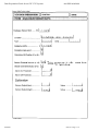
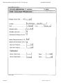
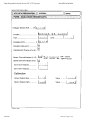
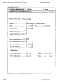
Data Preparation Guide for an STC UTC System
666/HH/16940/000
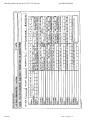
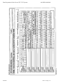
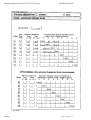
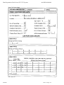
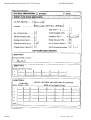
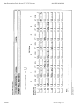
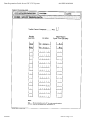
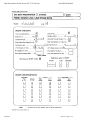
ISSUE STATE
Note: Source of documents is shown under Type as below.
1=Paper, 2=VAX, 3=Microfilm, 4=CALTEXT Disc, 5=DECmate Disc,
6=Paper Insert, 7=MAC Disc, 8=LIFESPAN, 9=SUN, 10=AMW
The document comprises the following components:
Pages
All
hh16940
Current
Issue
23
Type Part ID
10
666HH16940000
File ID
hh16940.doc
Issue 23 Page : ii
Data Preparation Guide for an STC UTC System
666/HH/16940/000
CONTENTS
1.
2.
3.
4.
5.
6.
7.
8.
INTRODUCTION ................................................................................................. 1
1.1
Purpose................................................................................................................................................ 1
1.2
Scope.................................................................................................................................................... 1
1.3
Related documents ............................................................................................................................. 1
1.4
Definitions ........................................................................................................................................... 1
1.5
Issue state and amendment................................................................................................................ 1
OVERVIEW ......................................................................................................... 3
2.1
Purpose................................................................................................................................................ 3
2.2
Scenario............................................................................................................................................... 3
2.3
SCNs .................................................................................................................................................... 4
COMPUTERS ...................................................................................................... 5
3.1
Description .......................................................................................................................................... 5
3.2
Identifier ............................................................................................................................................. 5
TC 12 PC ............................................................................................................. 6
4.1
Introduction ........................................................................................................................................ 6
4.2
Identifier ............................................................................................................................................. 6
4.3
Description .......................................................................................................................................... 6
SUB - AREAS...................................................................................................... 7
5.1
Introduction ........................................................................................................................................ 7
5.2
Identifier ............................................................................................................................................. 7
OUTSTATION TRANSMISSION UNITS ............................................................. 8
6.1
Introduction ........................................................................................................................................ 8
6.2
Identifier ............................................................................................................................................. 8
6.3
Telecommand 8 Transmission System.............................................................................................. 8
6.4
TC 12 Data Transmission System..................................................................................................... 9
OUTSTATION MONITORING UNITS................................................................ 10
7.1
Introduction ...................................................................................................................................... 10
7.2
Identifier ........................................................................................................................................... 10
JUNCTIONS ...................................................................................................... 11
8.1
Introduction ...................................................................................................................................... 11
8.2
Identifier ........................................................................................................................................... 11
8.3
Data format types ............................................................................................................................. 11
8.4
Junction J11111 ................................................................................................................................ 11
8.5
Junction J11121 and J11122............................................................................................................ 11
8.6
Junction J11141 ................................................................................................................................ 11
8.7
Junction J21111 ................................................................................................................................ 11
hh16940
Issue 23 Page : iii
Data Preparation Guide for an STC UTC System
666/HH/16940/000
8.8
Junction Plans................................................................................................................................... 12
8.9
Controller checks ............................................................................................................................. 13
9.
PELICANS......................................................................................................... 14
9.1
Introduction ...................................................................................................................................... 14
9.2
Identifier ........................................................................................................................................... 14
9.3
Pelican P11113.................................................................................................................................. 14
9.4
Pelican P31111.................................................................................................................................. 14
9.5
Pelican P31131.................................................................................................................................. 14
9.6
Pelican Plans ..................................................................................................................................... 14
10.
COUNT DETECTORS ................................................................................... 15
10.1
Introduction ...................................................................................................................................... 15
10.2
Identifier ........................................................................................................................................... 15
10.3
D21111............................................................................................................................................... 15
11.
QUEUE DETECTORS ................................................................................... 16
11.1
Introduction ...................................................................................................................................... 16
11.2
Identifier ........................................................................................................................................... 16
12.
SPECIAL FACILITIES ................................................................................... 17
12.1
Introduction ...................................................................................................................................... 17
12.2
Identifier ........................................................................................................................................... 17
12.3
F31111, F31112, F31113................................................................................................................... 17
13.
GREEN WAVES ............................................................................................ 18
13.1
Introduction ...................................................................................................................................... 18
13.2
Identifier ........................................................................................................................................... 18
13.3
Remote Requests .............................................................................................................................. 18
13.4
Special Facilities ............................................................................................................................... 18
13.5
Green Wave (triggered by vehicle detector) .................................................................................. 18
13.6
Green Wave Plans ............................................................................................................................ 18
14.
TIDAL FLOW ................................................................................................. 20
14.1
Introduction ...................................................................................................................................... 20
14.2
Identifier ........................................................................................................................................... 20
15.
CAR PARKS .................................................................................................. 21
15.1
Introduction ...................................................................................................................................... 21
15.2
Identifier ........................................................................................................................................... 21
15.3
Car Park C31131.............................................................................................................................. 21
15.4
Car Park C31121.............................................................................................................................. 21
15.5
Car Park C31111.............................................................................................................................. 21
15.6
Car Park C31211.............................................................................................................................. 21
hh16940
Issue 23 Page : iv
Data Preparation Guide for an STC UTC System
16.
666/HH/16940/000
CAR PARK SIGNS ........................................................................................ 23
16.1
Introduction ...................................................................................................................................... 23
16.2
Identifier ........................................................................................................................................... 23
16.3
Car Park Sign S11111 ...................................................................................................................... 23
16.4
Car Park Sign S31121 ...................................................................................................................... 23
16.5
Car Park Sign S31122 ...................................................................................................................... 23
16.6
Car Park Sign S31123 ...................................................................................................................... 23
16.7
Car Park Sign S11142 ...................................................................................................................... 23
17.
DIVERSIONS ................................................................................................. 24
17.1
Introduction ...................................................................................................................................... 24
17.2
Identifier ........................................................................................................................................... 24
17.3
Remote Request................................................................................................................................ 24
17.4
Diversion Sign List ........................................................................................................................... 24
17.5
Diversion Implementation Delay .................................................................................................... 24
17.6
Diversion Sign Implementation Delay ............................................................................................ 24
17.7
Dependent Diversion ........................................................................................................................ 24
18.
DIVERSION SIGNS ....................................................................................... 26
18.1
Introduction ...................................................................................................................................... 26
18.2
Essential Signs .................................................................................................................................. 26
18.3
Delayed Cancel Time ....................................................................................................................... 26
19.
ANALOGUE ENVIRONMENTAL SENSORS ................................................ 27
19.1
Introduction ...................................................................................................................................... 27
19.2
Identifier ........................................................................................................................................... 27
20.
REMOTE REQUESTS ................................................................................... 28
20.1
Introduction ...................................................................................................................................... 28
20.2
Identifier ........................................................................................................................................... 28
21.
AUTOMATIC PLAN SELECTION (APS)....................................................... 29
21.1
Introduction ...................................................................................................................................... 29
21.2
The Groups ....................................................................................................................................... 29
21.3
Priorities and Plan numbers............................................................................................................ 29
21.4
Plan Masks........................................................................................................................................ 29
22.
WALL MAPS.................................................................................................. 30
22.1
Introduction ...................................................................................................................................... 30
22.2
Telecommand 8 systems................................................................................................................... 30
22.3
TC 12 systems ................................................................................................................................... 30
23.
23.1
hh16940
SYSTEM WIDE VARIANTS ........................................................................... 31
Introduction ...................................................................................................................................... 31
Issue 23 Page : v
Data Preparation Guide for an STC UTC System
24.
24.1
25.
666/HH/16940/000
SCOOT AREA ............................................................................................... 32
Introduction ...................................................................................................................................... 32
SCOOT REGIONS ......................................................................................... 33
25.1
Introduction ...................................................................................................................................... 33
25.2
Identifier ........................................................................................................................................... 33
25.3
RBB ................................................................................................................................................... 33
25.4
RDD ................................................................................................................................................... 33
26.
SCOOT NODES............................................................................................. 34
26.1
Introduction ...................................................................................................................................... 34
26.2
Identifier ........................................................................................................................................... 34
26.3
N11111............................................................................................................................................... 34
26.4
N11113 and N31131.......................................................................................................................... 34
26.5
N11141............................................................................................................................................... 34
26.6
N11121............................................................................................................................................... 35
26.7
N21111............................................................................................................................................... 35
27.
SCOOT STAGES........................................................................................... 36
27.1
Introduction ...................................................................................................................................... 36
27.2
Identifier ........................................................................................................................................... 36
28.
SCOOT LINKS............................................................................................... 37
28.1
Introduction ...................................................................................................................................... 37
28.2
Identifier ........................................................................................................................................... 37
29.
SCOOT DETECTORS ................................................................................... 38
29.1
Introduction ...................................................................................................................................... 38
29.2
Identifier ........................................................................................................................................... 38
30.
30.1
31.
31.1
TIMETABLES ................................................................................................ 39
Introduction ...................................................................................................................................... 39
CASTS ........................................................................................................... 40
Introduction ...................................................................................................................................... 40
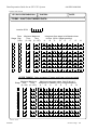
APPENDIX A - THE LAYOUT OF BERESFORD ST MARCUS .............................. 41
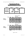
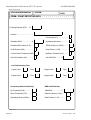
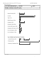
APPENDIX B - JUNCTION STAGE DIAGRAMS AND TIMINGS ............................ 45
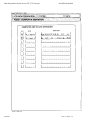
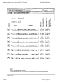
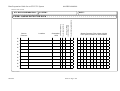
APPENDIX C - COMPLETED DATA FORMS FOR BERESFORD ST MARCUS ... 51
APPENDIX D - BLANK DATA FORMS.................................................................. 188
hh16940
Issue 23 Page : vi
Data Preparation Guide for an STC UTC System
1.
666/HH/16940/000
INTRODUCTION
1.1
Purpose
The aim of this document is to provide sufficient information, with the aid of worked
examples, to show how the essential features of a road system can be collected for input into
an STC UTC System.
A computer based Urban Traffic Control System that can adapt itself to the various traffic
patterns and flows within a town or city does so by modelling the road network. If this model
and hence the control of traffic is to be successful the computer must first be given accurate
details of the layout and features of the road network.
1.2
Scope
The features that are described in this document relate to an STC Urban Traffic Control
System. It is assumed that the reader is an experienced traffic engineer familiar with traffic
control and has available the System Handbook for an STC UTC System, reference 1.3.2(c).
1.3
Related documents
1.3.1
Parent Documents
1.3.1(a)
666/UH/16940/000
1.3.2
Reference Documents
1.3.2(a)
666/KE/16066/000
UTC Glossary of terms
1.3.2(b)
666/HD/16940/000
Data Preparation Handbook for an STC UTC System
1.3.2(c)
666/HE/16940/000
System Handbook for an STC UTC System
1.3.2(d)
666/HF/16940/000
SCOOT User Guide
1.3.2(e)
666/HE/43100/000
TC12 Installation, Commissioning and Maintenance
Handbook
1.3.2(f)
666/HI/16940/000
Data File Format Guide for an STC UTC System
1.3.2(g)
666/UH/16940/xxx
Customer Requirement Specification (replace xxx with
unique customer reference)
System Requirement Specification for an STC UTC
System
1.4
Definitions
See UTC Glossary of terms, reference 1.3.2(a).
1.5
hh16940
Issue state and amendment
Issue 01.00D
For review
Issue 01.00
First issue change ref. DC 7238/7239
Issues 02.00 to 07.00 Not created
Issue 08.00
Issue for UTC S/W release 8.0
Issue 23 Page : 1
Data Preparation Guide for an STC UTC System
666/HH/16940/000
Issues 09.00 to 14.00 Not issued
Issue 15.00
Updated to Word and to reflect version 15 UTC software
Issue 16.00
Updated to correct missing forms and to align with version
16 of the UTC software
Issue 17
Updated for UTC software release 17
Issues 18 to 20
Not issued
Issue 21
Updated for UTC software release 21
Issue 22
Not issued
Issue 23
Updated for UTC software release 23
hh16940
Issue 23 Page : 2
Data Preparation Guide for an STC UTC System
2.
666/HH/16940/000
OVERVIEW
2.1
Purpose
This section describes a road network for an imaginary town and the facilities and equipments
that make up a UTC network. In real life it is unlikely that everything described here would
appear within one town or city. Subsequent sections discuss each of these facilities and
equipments and show how the data is derived for the data entry forms.
It is strongly recommended that the engineer use this guide initially to work out his equipment
requirements. Subsequently, prior to factory testing it is usually necessary to complete the
data forms in full, either for the engineer's or STC's input.
2.2
Scenario
2.2.1
Beresford St Marcus is an old town with narrow winding streets. The Cummings
canal runs through the East side of the town over which the only crossings are
Bodger Bridge and Carter Crossing. Bodger Bridge operates a tidal flow system
for the morning and evening peaks. Carter Crossing is a lifting bridge that might
be raised two or three times a day. Extensive variable message signs are to be
used in the streets around these bridges to inform motorists when the tidal flow
system is operating and also to pass information if the Carter Crossing is raised.
2.2.2
The Maynard Shopping Centre is pedestrianised and there are three car parks in
close proximity to this centre. Signs are to be used on the outskirts of the town to
inform the motorists which car parks have spaces and which way to travel to
them. There are also signs close to each car park showing its status (FULL,
ALMOST FULL, SPACES, etc).
2.2.3
The network consists of six junction controllers and three pelican controllers. All
of these are to be operated under SCOOT control. The location of all the SCOOT
detectors has to be identified well in advance to enable the data transmission
requirements to be established. The junctions have a variety of different methods
of control such as demand dependent stages, removable stages by time of day,
parallel stage streams, secret no right turn signs etc.
2.2.4
On the main through street, Dickinson Drive, there is a fire station. They require
facilities to call Green Wave routes in 4 different directions for emergency
vehicles leaving the station.
2.2.5
Around the city there are to be some strategically placed counting and occupancy
detectors. With SCOOT this would not normally be necessary but the County
Engineer is doubtful that SCOOT works and wants to have the facilities for
Automatic Plan selection as well!
2.2.6
A wall map is required that shows the status of each junction and pelican using
coloured LEDs. Other equipments such as the lifting bridge and occupancy
detectors also have indicators on the map.
2.2.7
All equipments in the system have to be identified by System Code Numbers
(SCNs). Bearing in mind all the facilities mentioned above, the engineer should
hh16940
Issue 23 Page : 3
Data Preparation Guide for an STC UTC System
666/HH/16940/000
list all the items and work out how many control and reply bits of information are
required for each one. He should then be in a position to identify the number of
OTUs and hence the number of telephone lines that are required.
2.2.8
Figure 1 in Appendix A shows a map of the town.
2.3
SCNs
The reader is recommended to read the System Handbook, reference 1.3.2(c), in order to gain
an understanding of the SCN identification before reading any further.
hh16940
Issue 23 Page : 4
Data Preparation Guide for an STC UTC System
3.
666/HH/16940/000
COMPUTERS
3.1
Description
The majority of UTC Systems use one computer. Only where the number of signals is high or
the customer has special requirements is there a need for more than one computer.
3.2
Identifier
The computer SCN is addressed in the system by the letter "H". As Beresford St Marcus is a
small town there is only one computer that is given the SCN H01000. SCNs are always five
digits long and 15 characters are allowed for the description. If a second computer had been
required this would have the SCN number H02000.
hh16940
Issue 23 Page : 5
Data Preparation Guide for an STC UTC System
4.
666/HH/16940/000
TC 12 PC
4.1
Introduction
In systems with TC12 a PC handles the interface between the computer and the instation
modems. The PC has a number of intelligent modem driver boards, each of which could in
theory drive 96 OTUs with two control and six reply bytes. The exact capacity of each board
depends on the speed, telephone line configuration and number of control and reply bytes at
each site. The user should read the TC12 Installation, Commissioning and Maintenance
Handbook, reference 1.3.2(e), to get a better understanding of the setup of an OTU.
4.2
Identifier
Each TC12 PC is identified by the letter "E" followed by a five digit number. The first two
digits must be the same as the computer number.
4.3
Description
Within the PC there are intelligent modem driver boards each with 16 ports. Each of these
ports is configured from the TC12 data entry screen. The data entry is "intelligent" in as much
as when each OTU is added with the number of control and reply bytes, the remaining
capacity of that port is calculated and displayed.
hh16940
Issue 23 Page : 6
Data Preparation Guide for an STC UTC System
5.
666/HH/16940/000
SUB - AREAS
5.1
Introduction
A Sub-Area is a network of junctions, pelicans or equipments that normally form a traffic
entity. Everything in a Sub-Area usually changes plans at the same time, although this is not a
rule.
5.2
Identifier
Sub-Areas are identified by the letter "A" followed by a five digit SCN. The first two numbers
of this SCN define the Sub-Area. In Beresford St. Marcus, A11000 defines Sub-Area 11, the
Ansell Avenue area. E.g. J11111 is a junction within Sub-Area 11.
hh16940
Issue 23 Page : 7
Data Preparation Guide for an STC UTC System
6.
666/HH/16940/000
OUTSTATION TRANSMISSION UNITS
6.1
Introduction
An outstation transmission unit (OTU) on site interfaces between the equipment and the
telephone line back to the computer. Normally every controller has one OTU. In some cases
two controllers close together may share an OTU, particularly if one is a junction and the
other a pelican. As well as junction data the OTU may also have inputs connected to it from
any other piece of equipment capable of being controlled or monitored by the System, such as
car park status or diversion sign control. If these other equipments are a long way from a
junction controller, say greater than 200 metres, they may have their own dedicated OTU.
6.2
Identifier
An OTU is addressed in the system by the letter "X". As with every other piece of equipment
an OTU SCN has five digits, the only difference being that it must end in "0". If the junction
had been designated J01121 then the OTU would be designated X01120. J01122 would be a
second junction on the same OTU. If there was a pelican on the same OTU it could be
designated P01121, although to avoid duplication of numbers it may be better to give it the
number P01123. Note the system uniquely identifies them because one has a P prefix the
other a J prefix. Similarly if there was a counting detector this could be allocated D01127. By
using this type of numbering it is easy to see to which OTU any piece of equipment is
connected.
6.3
Telecommand 8 Transmission System
With the STC Telecommand 8 data transmission system, a modem can carry up to four 16-bit
addresses. This could be used so that one OTU uses all four addresses or the addresses are
shared between up to four OTUs. In this case each OTU would have only one address. The
junction and pelican data at an OTU site must be returned in the first 16-bit address on an
OTU. Other addresses are then used to return SCOOT detector or other reply information.
A SCOOT detector uses 4 bits on an address, thus four SCOOT detectors can be returned in
one 16-bit address. If the junction data is using all of the first 16-bit address then the
maximum number of SCOOT detectors that can be handled on one OTU is eight. This is
because the total number of wiring inputs into the OTU is restricted to 24, each return bit
from the controller or controllers being one input.
Most SCOOT junctions use at least two addresses and frequently three or four. To optimise
the use of the instation data transmission equipment it is important to calculate the number of
addresses at each site and then allocate the internal addresses accordingly. e.g. two 2-address
OTUs can be placed on one modem or perhaps one 3-address OTU and one single address
OTU. An example of a single address OTU may be a pelican with its own OTU and perhaps
two SCOOT detectors. All this information can be returned within one 16-bit address, with bit
numbers ranging from 0 to 15.
The individual configuration of each OTU is shown with the information for the main
equipment attached to the OTU. The IRN number is the internal computer address and can be
in the range 1 to 512.
With a Telecommand 8 system an OTU cannot be allocated over a 4-address boundary. Thus
a 2-address OTU cannot be allocated internal addresses 4 and 5 for example. The primary
address is the starting address for that OTU on a modem. Each OTU is wired individually to
determine the address. This number is one of 1, 4, 7 or 13. If there were two 2-address OTUs
on a modem, the first would start at primary address 1 and the other at 7.
The address number determines how many addresses are used on the OTU. A sampled input
pointer determines at what point in the addresses the SCOOT detector data is returned. A
hh16940
Issue 23 Page : 8
Data Preparation Guide for an STC UTC System
666/HH/16940/000
value of 16 would indicate that they are starting on the second address. Note also that SCOOT
detectors must be the last equipments on an OTU.
NOTE:The internal numbering of each bit within an address goes from 0 to 15.
6.4
TC 12 Data Transmission System
TC12 is a more modern data transmission system that can run at 600/1200 baud. The
fundamental difference between Telecommand 8 and TC12 is that each OTU operates in 8-bit
control and reply bytes as opposed to the Telecommand 8 system of 16-bit addresses. An
OTU can be configured for up to three control bytes (24 bits) and up to 14 reply bytes (112
bits).
The freestanding OTU has 16 outputs and 32 inputs. An input can be defined as a reply bit
from a controller or piece of equipment, or a single SCOOT detector. The OTU can be
configured for up to six count, queue or occupancy detectors. Note that a U/D SCOOT
detector occupies two inputs.
There is a maximum OTU capacity for each TC12 modem. OTUs may be configured on the
same modem until this capacity is reached and this is determined by summing the number of
control and reply bytes configured together with the total number of OTUs added. The data
entry software advises the user of the spare capacity available on each modem.
hh16940
Issue 23 Page : 9
Data Preparation Guide for an STC UTC System
7.
666/HH/16940/000
OUTSTATION MONITORING UNITS
7.1
Introduction
A link can be made between a Remote Monitoring System and STC UTC systems. This
enables RMS faults to be recorded into the UTC log and also the archiving of count detector
data from remote sites.
7.2
Identifier
An OMU site is identified by the letter "Y" followed by a five digit number following the
standard UTC convention.
hh16940
Issue 23 Page : 10
Data Preparation Guide for an STC UTC System
8.
666/HH/16940/000
JUNCTIONS
8.1
Introduction
This section describes each of the five junctions in the town and how the data is interpreted.
All junctions have had the PROMs configured for real-time clock synchronisation, remote
reconnect, lamp failure and manual control.
The stage diagrams and intergreen tables are contained in Appendix B .
8.2
Identifier
A junction controller is addressed in the system by the letter "J" and the normal five digits.
The first junction on an OTU would normally have the last digit as "1" and the second the last
digit as "2".
8.3
Data format types
The control and reply data bits for junctions are defined within format types. These format
types define the data bit position of items such as real time synchronisation, stage demand
bits, remote reconnect reply etc. The data bits start after the stage force bits.
8.4
Junction J11111
This is a straightforward 2-stage controller with both stages forced, i.e. there are no demand
dependent stages here.
This OTU is also controlling a pelican P11113, which is 150 metres away, by a linking cable.
This same cable is also driving a car park information sign at the pelican site.
NOTE: There is some disparity between the notation for 141 controller bits and
those used by STC. It is expected that this disparity will soon disappear.
However, it should be remembered that any new feature that appears
within a 141 controller will not automatically appear on STC systems,
although in the course of time they may well do so.
8.5
Junction J11121 and J11122
The controller at this site is controlling two junctions, J11121 as stream 1 and J11122 as
stream 2. Both have a demand dependent stage. F1-F3 control J11121 and F4-F6 control
J11122. As far as the computer is concerned J11122 is a separate junction and therefore F4-F6
translates directly into F1-F3. Certain bits are common to both junctions such as CS, MC, RR,
DF, LF1 and LF2. These bits are returned in the format type for the first junction J11121.
It is recommended that streams on the same controller are always allocated to the same link
list. Then if any fault occurs both streams are dropped from computer control.
For junction J11121 a push button pedestrian demand increases the minimum stage length of
stage 2 and the intergreen from stage 2 to stage 3.
8.6
Junction J11141
This is a 4-stage junction. Stages 2 and 4 are demand dependent, with stage 4 being an all
round pedestrian stage with no traffic movements. The OTU here also returns information on
city car park signs and from a counting detector, which is used for automatic plan selection.
8.7
Junction J21111
This is a 3-stage junction with no demand dependent stages. The bridge into the town,
downstream from this junction, operates a tidal flow system in the morning and evening
peaks. There is a sign on the southbound approach to J21111 that tells drivers to turn left only
hh16940
Issue 23 Page : 11
Data Preparation Guide for an STC UTC System
666/HH/16940/000
during the evening peak here. The OTU here controls this sign. This is driven as a special
facility within the UTC system. There are also two counting detectors sited near this junction
that are used for APS.
Stage 3 is used as a clearance stage for use in the evening peak and is omitted during the rest
of the day. Under SCOOT control this is called for a fixed period of 15 seconds and is
designated a removable stage.
8.8
Junction Plans
8.8.1
Every junction and pelican in the system can be allocated 40 fixed time plans, 6
SCOOT translation plans and 100 green wave plans. Individual configurations
may vary according to particular customer requirements; see 1.3.2(c).
The fixed time plans are allocated numbers 1 through 40, the SCOOT plans 41 through 46
and the green wave plans 48 through 147. Note: Plan 47 is known as the Test Plan and is used
for temporary changes to plan timings. It is invoked by use of the OFST command. The
construction of SCOOT plans is covered in the section on SCOOT.
Detailed checks are carried out during plan preparation to ensure that the structure of the plan
is correct. If for example, the junction has three stages and B is omitted then the controller
must have an intergreen defined for the change from A to C. If a stage is demand dependent
then it must have the correct demand bit associated with it if it is to be forced.
The times allocated to each stage are event times within the plan cycle time and are not stage
duration times.
J11111
A typical plan for J11111 might look like:
J11111 CY60, A 01, B 34
This shows that the junction has a 60 second cycle with A forced at the first second in the
cycle and B forced 33 seconds later at second 34 in the cycle. Remember this junction has no
demand dependent stages. The green time for stage A would be 33 seconds less the B to A
intergreen of 9 seconds. The green time for stage B would be 27 seconds less the A to B
intergreen of 7 seconds. The position of the event times are important as they determine the
offset to adjacent junctions for linking. This junction is forcing stage A 10 seconds before
stage A at J11121. The measured offset on the street would be slightly different as the
preceding intergreens are different.
J11121
This junction has stage B demand dependent. If this stage is to be enabled the plan might look
like:
J11121 CY 70 A 11, B 33, AB 35, C 53
This plan holds the controller on stage A if there is no local demand present for stage B. Stage
B is given a two second window that allows the controller to start a change from stage A to
stage B. The window is closed at time 35 but the controller continues its move into stage B
and stays there until time 53 when stage C is forced. With modern microprocessor controllers
the window could be shortened to one second.
J11121 CY 70, A 11, B 33, C 53
This plan forces a demand for stage B from the computer, so that stage B appears every cycle.
J11122
This junction has three stages all forced. The plan may look like:
J11122 CY 70, A 11, B 30, C 55
J11141
This junction has two demand dependent stages B and D. A typical plan enabling both of
these stages may look like this:
hh16940
Issue 23 Page : 12
Data Preparation Guide for an STC UTC System
666/HH/16940/000
J11141 CY 95, A 01, B 22, AB 24, C 31, D 79, AD 81
In this plan if there is no demand for stage B then the running time is given to stage A, which
also picks up the time if there is no demand for stage D.
J21111
This junction only uses stage 3 as a clearance stage during the evening peak.
The evening peak plan may look like:
J21111 CY 120, A 01, B 65, C 97
For the rest of the day the plan may look like:
J21111 CY 70, A 22, B 59
8.9
Controller checks
Controller checks is a program, usually run during the night, which carries out checks on the
controller timings such as intergreens, minimum greens etc. This program is really a left-over
from the days when controllers were much less reliable and their timings were likely to drift.
With modern microprocessor controllers it is debatable whether this needs to be run. The
normal computer operation carries out checks for intergreens and minimum violations all the
time.
hh16940
Issue 23 Page : 13
Data Preparation Guide for an STC UTC System
9.
666/HH/16940/000
PELICANS
9.1
Introduction
This section describes each of the three pelicans in the system and how the data is interpreted.
All pelicans have lamp failure monitoring, most also have the remote reconnect facility.
9.2
Identifier
A pedestrian controller is addressed in the system by the letter "P" followed by a five digit
number.
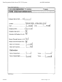
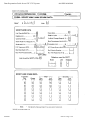
9.3
Pelican P11113
This is controlled from the same OTU as J11111 and allows pedestrian access from the park
area to the paths and facilities of the canal. The local configuration is:
Not GX time
21
GX time
7
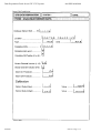
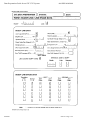
9.4
Pelican P31111
This allows pedestrians access to the Castle from the shopping Centre and associated car
parks. It is on an OTU that replies the occupancy of the car park and consequently has a
reduced number of reply bits. The local configuration is:
Not GX time
19
GX time
7
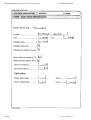
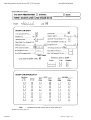
9.5
Pelican P31131
This allows pedestrians access to the Shopping Centre from the car park C31131. It is
controlled from the same OTU as the Fire station and car park status bits. The local
configuration is:
Not GX time
17
GX time
7
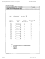
9.6
Pelican Plans
Pelican plans use the same numbers as those for junction plans.
P11131 CY 60, P 33, V 35
In this plan the pelican is allowed to change to pedestrians at time 33 seconds in the cycle.
The window automatically closes after two seconds at time 35 seconds.
If it is required to force the pedestrian stage the "PX" bit is sent, e.g.
P11131 CY 60, P 33, V 35
A pelican may be double cycled by repeating the event times twice e.g.
P11131 CY 70, P 1, V 3, P 36, V 38
hh16940
Issue 23 Page : 14
Data Preparation Guide for an STC UTC System
10.
666/HH/16940/000
COUNT DETECTORS
10.1
Introduction
The City uses count sites for three main purposes, calculating car park occupancy, providing
count information and for triggering APS.
NOTE:
Count detector information can be returned after bit 15 (as well as
before) on the OTU but must be before the SCOOT detectors.
10.2
Identifier
Count detectors are addressed in the system by "D" followed by a five digit number.
There are six counting detectors in the system, D21111, D21112 and D11141 are used in
association with automatic plan selection. D31121, D31122 and D31123 are associated with
entries and exit for car park C31121.
If it is decided to use some of the SCOOT detectors as counting detectors then extra "D"
numbers can be allocated to the system. These are effectively dummy numbers and SCOOT
links can be added or removed from them. Within data entry they are allocated type 0.
10.3
D21111
Detector D21111 returns occupancy data as well as counting data. The same "D" number is
used for both.
hh16940
Issue 23 Page : 15
Data Preparation Guide for an STC UTC System
11.
666/HH/16940/000
QUEUE DETECTORS
11.1
Introduction
It is important not to confuse queue detectors with occupancy detectors. A queue detector is
triggered when a vehicle is stationary on the detector for a predetermined length of time. An
occupancy detector measures the amount of time a detector is occupied.
There is one queue detector in the system located just to the West of junction J11121. It is
intended that this detector be used along with the counting detectors D21111 and D21112 in
the decision making process for the automatic plan selection.
11.2
Identifier
A queue detector is addressed in the system by a letter "Q" followed by a five digit number.
hh16940
Issue 23 Page : 16
Data Preparation Guide for an STC UTC System
12.
666/HH/16940/000
SPECIAL FACILITIES
12.1
Introduction
Special facilities are used to control equipments with two states. The equipment is turned “on”
when the single control bit is sent out. Examples of this would be secret signs, where a reply
confirmation can be configured and the confirmation of a green wave, where no reply is
needed.
12.2
Identifier
A special facility is addressed in the system by the letter “F” followed by a five digit number.
12.3
F31111, F31112, F31113
In Beresford St. Marcus, three special facilities are used to indicate to the users in the Fire
Station that the selected Green Wave is active. They see this as a light, typically green, on the
selection panel.
hh16940
Issue 23 Page : 17
Data Preparation Guide for an STC UTC System
13.
666/HH/16940/000
GREEN WAVES
13.1
Introduction
The Green Waves are designed to allow fire engines to leave the town through either Carter
Crossing or Bodger Bridge, or to access the airport. They are called using a Green Wave
Route Selection Box located at the fire station. Once the route is active a lamp lights on the
box indicating the active route. Additional emergency vehicles may pass down the route in
successive waves.
13.2
Identifier
A Green Wave is addressed in the system by the letter "G" followed by a five digit number.
13.3
Remote Requests
Each button on the Selection Box is seen by the System as a Remote Request. This is
associated with a green wave plan that starts when the button is first pressed. Each remote
request is allocated a "Z" number followed by a five digit number; the green wave is then
allocated to that remote request number.
13.4
Special Facilities
In addition to a button for each route the box has a lamp for each route. This is seen by the
System as a Special Facility. When the route is active the Special Facility is asserted and the
lamp lights. Each special facility is allocated an "F" number followed by a five digit number.
This is then linked with the associated remote request on the remote request data entry screen.
The convention is for the Special Facility and Remote Request SCNs to match, e.g. F31111
and Z31111.
13.5
Green Wave (triggered by vehicle detector)
In Beresford St Marcus the Fire station is sufficiently close to the first junction that the timing
for the Green Wave is predictable. If the junction was a long way away, or progression was
unpredictable the Green Wave could be started by using a special vehicle detection system.
Then, as the firemen left the station, they would pre-select the route and when the vehicle
subsequently activated the detector it would start the Green Wave route. The single bit that is
returned by the detector is known as the EV bit.
13.6
Green Wave Plans
Each green wave plan contains the timings for one route only and may consist of up to 16
intersections and/or pelicans. Green Wave route 1 G11111 uses plan 50 and progresses the
emergency vehicle through J11141, P11113 and J11111.
The junction plan may look like:
J11141 OFFSET 10 C 30
J11111 OFFSET 34 B 60
The pelican plan may look like:
P11113
OFFSET 20, V 45
At the first junction J11141 stage C is called 10 seconds after the remote request for the green
wave is started and is held for 30 seconds duration. The pelican P11113 is then inhibited from
changing for 45 seconds, 20 seconds after the remote request was called. Finally J11111 stage
B is called 34 seconds after the start of the green wave for a duration of 60 seconds. It is
common practice for the durations to be increased the further from the starting point the
vehicle travels to compensate for unexpected hold ups.
hh16940
Issue 23 Page : 18
Data Preparation Guide for an STC UTC System
666/HH/16940/000
After each pelican or junction completes the Green Wave, it is "crash" changed onto the
previous running plan to resume correct operation as quickly as possible. If this is thought to
be unsatisfactory, then the plan can contain an optional clearance stage that is run as the green
wave terminates, e.g.
J11141 = DUR 20, C 10, A 20
hh16940
Issue 23 Page : 19
Data Preparation Guide for an STC UTC System
14.
666/HH/16940/000
TIDAL FLOW
14.1
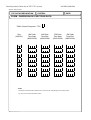
Introduction
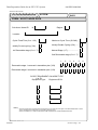
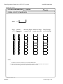
The Tidal Flow Scheme (TFS) controls the centre lane of Bodger Bridge, a three lane road, by
means of overhead signs. The signs face in both directions and show one of the following
aspects:
Straight Ahead Arrow
Move Over Arrow
Red Cross
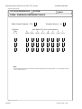
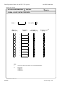
The TFS has a number of signs that are all controlled by one local, programmable, controller.
To change from, say, centre lane inbound to centre lane outbound the sequence of sign aspects
shown below would be used:
Inbound Sign
Outbound Sign
Straight Ahead
Red Cross
Move Over
Red Cross
Red Cross
Red Cross
Red Cross
Straight Ahead
The duration of the Move Over aspect is one minute and that of the double Red Cross is three
minutes. After changeover the Straight Ahead arrow runs for a minimum of four minutes.
These times are programmed into the TFS local controller and may be changed from time-totime by re-programming the controller.
14.2
Identifier
The tidal flow scheme is identified by the letter "L" followed by a five digit number.
hh16940
Issue 23 Page : 20
Data Preparation Guide for an STC UTC System
15.
666/HH/16940/000
CAR PARKS
15.1
Introduction
As the development of the Maynard Centre was piecemeal the car parks around the centre use
a number of different ways of reporting their status to the UTC System.
15.2
Identifier
A Car Park is addressed in the System by the letter "C" followed by a five digit number.
15.3
Car Park C31131
This car park has some intelligence of its own and indicates its state directly using three bits.
Two of the bits (CA and CF) are calculated from the occupancy data returned to the unit from
local count detectors, the third bit (CC) indicates whether or not the car park has been closed
by the car park's own operator. Because this bit is present the UTC System operator is unable
to close the car park. Omitting the CC bit means that only the UTC System operator can close
the car park.
The reply data co-exists with the fire station control panel and pelican P31131 on the OTU
31130.
15.4
Car Park C31121
This car park has no on-site intelligence and the System uses count detectors located at the
entrance and exits to determine the car park state.
Standard count detectors are located on all approaches to and exits from the car park. This car
park has two exits and one entrance requiring three detectors altogether, D31121, D31122 and
D31123 respectively. Each detector has been set up to change state when two vehicles have
passed over the loop so that an accurate occupancy can be calculated.
The car park capacity is 650 cars, which is large by local standards. Because of its proximity
to the Maynard Centre it is also the most popular car park in the System. Most cars arriving at
the car park come from Dickinson Drive and Maile Mews and roughly 20 cars arrive at the
park after the car park sign S31121 has changed to the full state. Consequently the full
increasing threshold has been set to 620 (allowing for some errors) and the almost full
increasing threshold to 580. In order to stop the signs changing state frequently and to provide
good information to new arrivals at the town, the two decreasing thresholds have been set to
600 and 550 respectively.
The car park equipment that controls the barrier is connected to the system. When the system
believes that the car park is full the barrier is not raised.
15.5
Car Park C31111
The on-site intelligence at this car park derives its own occupancy from internal count
detectors and controls the barriers itself.
The data is returned on OTU X31110 as a 13 bit Binary Coded Decimal value. Although the
system allows up to 1999 cars in a car park this car park only has capacity for 300.
Because of its location on the west of town it is not very popular, except for visitors to
Barnard Castle. For this reason the increasing thresholds have been set to 290 and 280, whilst
the decreasing thresholds have been set to 260 and 250.
15.6
Car Park C31211
The airport parking facilities use a Pay and Display system where ticket machines are
connected to a central PC system. This in turn is to be connected to the UTC system that can
hh16940
Issue 23 Page : 21
Data Preparation Guide for an STC UTC System
666/HH/16940/000
then receive a regular update of ticket sales. By choosing a suitable conversion factor the
UTC system can then maintain an approximate occupancy record for this parking facility.
hh16940
Issue 23 Page : 22
Data Preparation Guide for an STC UTC System
16.
666/HH/16940/000
CAR PARK SIGNS
16.1
Introduction
There are currently five car park signs on the System. The Council acknowledges that this is
insufficient but current finances do not permit more to be installed. Priority has been given to
the route over the Carter Crossing that is the common tourist approach to the City. Most
people who cross the Bodger Bridge are commuting to and from work.
16.2
Identifier
Car park signs are addressed by the System using the letter "S" followed by five digits.
There are three types of car park sign:
16.2.1
Entrance
This sign is for a single car park and is located at the entrance to its car park. The legend
would normally say "SPACES" or "FULL".
16.2.2
Named
This type of sign directs motorists to a specific car park; the legend may display "SPACES",
ALMOST FULL", "FULL" or "CLOSED".
16.2.3
City
This type of sign directs motorists to an area of the city, giving information on the state of a
number of car parks.
16.3
Car Park Sign S11111
This sign is intended to direct traffic to either C31121 or C31111 depending upon their state.
Because of the large size of C31121 it is preferred to fill this rather than C31111 and so a City
sign is used. C31121 being used as Group 1 and C31111 as Group 2. In this way people are
directed first to C31121 and when it becomes full to C31111.
16.4
Car Park Sign S31121
This sign directs people to one of the three car parks using a city sign, firstly C31121, then
C31131 and lastly C31111.
16.5
Car Park Sign S31122
This sign is at the entrance to C31121 and controls the barrier stopping access to the park. If
the car park's entrance state is SPACES then the barrier is allowed to rise, if its full then it
remains down.
16.6
Car Park Sign S31123
This is a named sign on the approach to the car park indicating whether or not there are
spaces.
16.7
Car Park Sign S11142
This city sign indicates whether or not there are spaces in the city centre car parks; the three
car parks are considered as a group to determine the sign state.
hh16940
Issue 23 Page : 23
Data Preparation Guide for an STC UTC System
17.
666/HH/16940/000
DIVERSIONS
17.1
Introduction
Beresford St Marcus has three diversions:
a) The first is associated with the Carter Crossing lifting bridge. When the bridge
is raised the signs V11111 and V11112 are changed to indicate to motorists
that the bridge is closed and that they should divert in the direction indicated.
This diversion has been allocated the number U11111.
b) A single sign version of U11111 for when Nash Terrace is closed is termed
U11112.
c) The second diversion is associated with the closure of Nash Terrace for the
annual beer festival. This diversion has been allocated the number U11121 and
uses the diversion signs V11121 and V11122. It is introduced by an entry in
the date of year timetable or by operator command.
17.2
Identifier
A diversion in the system is addressed as a "U" followed by a five digit number.
17.3
Remote Request
The lifting bridge across the canal was not designed with traffic control in mind. Everyone
considers it possible and indeed beneficial to automatically start the diversion when the bridge
lifts, but the canal and traffic authorities cannot agree on who should pay for the necessary
adaptation. Until this is resolved a latching push button has been installed in the control panel
for the bridge. This is seen by the UTC System as the remote request, Z11111, moving from 0
to 1 and consequently the diversion is called. When the button is released, a call is sent to
cancel the diversion.
17.4
Diversion Sign List
This is used to nominate those signs that are set by the System when the associated diversion
is active.
17.5
Diversion Implementation Delay
The System provides a facility to delay the introduction of a diversion by up to 15 minutes.
For Beresford St Marcus there is no reason to use this facility.
17.6
Diversion Sign Implementation Delay
Traffic builds up on the approach to the bridge because locals know what is happening and
choose to queue rather than drive around. It is therefore necessary to continue to divert traffic
away from the bridge for a minute after it has come down. In order to achieve this the delay
value is set to 0.5 minutes and the diversion sign group for all affected signs is set to 1.
17.7
Dependent Diversion
When Nash Terrace is closed and the lifting bridge is raised this has a dramatic effect on the
network. It is accepted under these conditions that vehicles will queue regardless of what is
done and a single sign diversion U11112 is actioned.
In order to decide what diversion is to be actioned it is first necessary to decide what is
supposed to happen when more than one diversion is requested at any instant in time. In the
case of Beresford St Marcus there are two diversions, U11111 and U11121, which occur if no
hh16940
Issue 23 Page : 24
Data Preparation Guide for an STC UTC System
666/HH/16940/000
other diversions are active. If both are requested then U11112 is started and the others
cancelled.
In order to use this facility it is necessary to set up a diversion group and diversion types. The
group chosen is number 1 and the diversion types, U11111 is 1, U11112 is 2 and U11121 is 3.
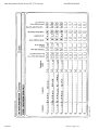
17.7.1
Dependent Diversion Rule Tables
This table is used to determine which state the diversions and plan on a sub-area should be in
operation after a new diversion request. The table is indexed using the current state of the
diversions in the 'group' and the type of the new diversion request.
The state is calculated using the type of each diversion to generate a binary value. Type 1
represented by "001", 2 by "010" and 3 by "100". For each active diversion the binary patterns
are ANDed together, for example if type 1 and 2 are active the pattern becomes "011" or
decimal 3.
This may be simply represented using a table. The rows show which diversion is starting
whilst the columns show diversions which are already active. The 'cell' selected becomes the
new state for the diversions in the group.
Currently active diversion types
New Request
none 1
2
3
1 & 2 1 & 3 2 & 3 all 3
1
1
1
2
2
0
0
0
0
2
2
2
2
2
0
0
0
0
3
4
2
2
4
0
0
0
0
Do not forget that this is expressed in terms of states, so that the two entries with state of 4
are really requesting type 3 (pattern "100") to be started.
The right hand part of the table is all zeros as it is not possible to get into that state. If it
occurs then the simplest solution is to cancel all diversions.
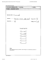
This now needs to be translated into the state order for data entry.
New
Current state
Request
none 1
2
3
4
5
6
7
1
1
1
2
0
2
0
0
0
2
2
2
2
0
2
0
0
0
3
4
2
2
0
4
0
0
0
Two columns have been switched because a state of 4 represents type 3 active, whilst a state
of 3 represents types 1 and 2 active.
17.7.2
Plan Diversion Rule Table
The System then uses the state selected to determine which plan should be implemented in
the sub-area nominated for this diversion. For each state 3 plans are specified - one for the
AM peak, one for the PM peak and the other for all other times.
17.7.3
Diversion Day Sectors Data
For each day of the week this allows different AM peak, PM peak and hence Off-peak times
to be specified. The start and times of each peak are entered and the System determines the
Off-peak period from this.
17.7.4
Diversion Plan Delay Switching Timetables
This is used to select a delay to be used when starting or stopping a plan. It uses the new state
and the data is specified in 30-second intervals. It is considered in Beresford St Marcus that
there is little point in delaying the introduction of a plan, but because of traffic between the
sign and junctions it is sensible to delay the removal by around 1 minute.
hh16940
Issue 23 Page : 25
Data Preparation Guide for an STC UTC System
18.
666/HH/16940/000
DIVERSION SIGNS
18.1
Introduction
There are four diversion signs in Beresford St Marcus associated with diversions, V11111,
V11112, V11121 and V11122. As their SCNs suggest they are associated with three OTUs
and occupy a single control and reply bit.
18.2
Essential Signs
Because of the nature of the road layout in Beresford St Marcus the failure of one sign does
not stop a diversion being implemented. Hence no signs are marked as essential.
18.3
Delayed Cancel Time
The signs associated with the lifting bridge are required to continue to operate for one minute
after the bridge is lowered. In order to achieve this the "Diversions Sign Group Number" is set
to 1 and the delay for the diversions to 0.5 minutes.
hh16940
Issue 23 Page : 26
Data Preparation Guide for an STC UTC System
19.
666/HH/16940/000
ANALOGUE ENVIRONMENTAL SENSORS
19.1
Introduction
The Analogue Sensors measure levels of pollution at strategic locations in Beresford St.
Marcus. Analogue environmental measurements are detected at each sensor and converted to
digital data before being transmitted to the UTC system. The UTC system calibrates the data
into corresponding units, such as parts per million, which are then available for display on the
MMI screen and also stored for future reference.
Five sensors are located at each site, measuring the following information:
• Sulphur Dioxide (SO2)
• Nitrogen Dioxide (NO2)
• Status Information (Dummy) Channel
• Carbon Monoxide (CO)
• Temperature (°C)
As a convention in the Beresford St. Marcus system the last digit of the SCN is standardised,
so that:
W11111, W11121, W21111 and W31111 are all Sulphur Dioxide sensors.
In a similar fashion, sensors having 2 as the last digit measure Nitrogen Dioxide, 3 are the
Status Channels, 4 are for Carbon Monoxide and 5 measure temperature.
Each sensor has two thresholds associated with it, so that when the Alarm On level is reached
an alarm is triggered for that sensor. Similarly, when the Alarm Off level is reached the alarm
is cleared.
All the Sulphur Dioxide sensors and the two CO sensors W21114 and W11124 are joined
together in a sensor group such that when the measured levels from all these pass their
respective Alarm On thresholds a CAST is triggered. This CAST modifies SCOOT
parameters and implements diversion signs to reduce the number of vehicles flowing into the
city. When the measured levels of all the sensors in the group pass their Alarm Off levels a
second CAST is triggered to restore the traffic parameters to their previous values.
19.2
Identifier
An analogue sensor is identified by the letter “W” followed by a five digit number.
hh16940
Issue 23 Page : 27
Data Preparation Guide for an STC UTC System
20.
666/HH/16940/000
REMOTE REQUESTS
20.1
Introduction
Remote requests are used to inform the system of an event and/or to implement automatically:
(a) a diversion
(b) green wave
(c) the raising of a bridge
(d) the raising of a bridge and a diversion request
(e) implementing solar override on a sub-area when fog is detected.
A user defined remote request may be used to put an entry in the system log when a remote
request bit is set, and a different message when the remote request bit is cleared.
20.2
Identifier
Remote requests are addressed in the system by the letter "Z" followed by five digits.
In Beresford St Marcus there are four remote requests designated in the system. The first three
are all requesting Green Waves from the fire station Green Wave box. The fourth is derived
from the Carter Crossing lifting Bridge. When the bridge is raised, this returns a bit on the
OTU X11110, which informs the operator that the bridge is raised and implements diversion
U11111.
The low-lying areas around Gotch Graveyard are prone to fog and a fog detector is installed
near Bodger Bridge. This fog detector raises a remote request (Z11131) that causes the solar
override to be sent to those controllers equipped with an SB bit in subarea 21.
The local authority wishes to have a record of the opening and closing of the Gotch
Graveyard access gates. A suitable microswitch has been installed which is connected to the
OTU at the Nash/Anderson intersection, to activate a user defined remote request.
hh16940
Issue 23 Page : 28
Data Preparation Guide for an STC UTC System
21.
666/HH/16940/000
AUTOMATIC PLAN SELECTION (APS)
21.1
Introduction
The County Engineer has yet to be convinced that SCOOT can successfully operate around
the Bodger Bridge where the tidal flow system operates. Accordingly he wants a number of
fixed time plans to be selected depending upon the status of the three count detectors and one
queue detector already available. These are D21111 heading south on Nash Terrace, D21112
heading west, D11141 heading south on Clarke Quay and Q11121 located between the two
junctions at the west of Bodger Bridge.
If all the count detectors have vehicle counts above their trigger threshold then plan 20 is
selected in sub-area 11; if the occupancy level of the detector D21111 is above its threshold
then plan 21 is selected. If detector Q11121 shows a queue then plan 22 is selected. If the
count and occupancy detectors have triggered then plan 23 is selected. Because of the short
link between the two junctions plan 22 is the highest priority.
21.2
The Groups
APS is driven by the state of three groups. These are the count, queue and occupancy groups
referred to in the database as V, Q and O respectively. Each group can consist of up to five
detectors. The group's state is determined from either:
a) any of the group triggering, or
b) all of the group triggering.
The latter is the default action.
21.3
Priorities and Plan numbers
As described above, of the four possible plans, plan 22 has the highest priority and occupies
number 4 priority slot, followed by plans 23, 21 and 20.
21.4
Plan Masks
Each mask is associated with a priority; it makes sense to start with the easiest first. Priority 4
occurs when the queue group triggers, so it is simply "Q". Priority 1 occurs when the count
(volume) group triggers, so it is simply "V". Priority 2 occurs when the occupancy group
triggers, which is "O". The last trigger occurs when both count (volume) and occupancy
group triggers "V.O", that is priority 3.
hh16940
Issue 23 Page : 29
Data Preparation Guide for an STC UTC System
22.
666/HH/16940/000
WALL MAPS
22.1
Introduction
Beresford St Marcus has a wall map with each item of equipment including the diversions and
green waves shown by LED indications. The operation of each digital output to the wall map
is defined in the System Handbook for an STC UTC system. To summarise, each piece of
equipment has the following number of bits allocated to it:
bits
Junctions
3
Pelicans
3
Queue Detectors
3
Car Parks
1
Diversions
1
Diversion signs
1
Green Waves
3
Count Detectors
2
22.2
Telecommand 8 systems
The number of bits for each equipment are allocated to a wall map word number and a
starting bit position. There are a total of 128 wall map words available each with 8 bits. There
are no rules as to the position of each piece of equipment, different items can be mixed on the
same word. One piece of equipment can also cover two adjacent words. i.e. J11111 may start
on wall map word number 1 bit position 7 and finish on wall map word number 2 on bit
position 1.
On the Telecommand 8 highway the digital I/O chassis that drive the wall map are in
positions 0 or 4.
22.3
TC 12 systems
With TC 12 digital I/O there are 128 words each of 16 bits. The digital I/O rack can be in
position 0, 1 or 2.
A TC 12 PC can support two digital I/O racks.
hh16940
Issue 23 Page : 30
Data Preparation Guide for an STC UTC System
23.
666/HH/16940/000
SYSTEM WIDE VARIANTS
23.1
Introduction
Each customer can set up tolerances for controller and transmission checks and file life times
for their particular system. The system is supplied with standard defaults. It is not necessary
for a new customer to produce a data configuration for this screen.
hh16940
Issue 23 Page : 31
Data Preparation Guide for an STC UTC System
24.
666/HH/16940/000
SCOOT AREA
24.1
Introduction
Before entering SCOOT data it is recommended that the engineer should read the SCOOT
User Guide. The area data defines a number of strategic parameters that apply to the whole
SCOOT network.
hh16940
Issue 23 Page : 32
Data Preparation Guide for an STC UTC System
25.
666/HH/16940/000
SCOOT REGIONS
25.1
Introduction
The Beresford St Marcus network is to be divided into two regions. A region is a group of
nodes that are operated under SCOOT control at the same common cycle time. Normally
these are nodes where co-ordination is desirable between them. At this stage it is only
necessary to get the basic configuration of the SCOOT database correct as there will
undoubtedly be changes during validation and fine tuning. Facilities such as congestion links,
gating and SOFT need not be set up at this stage. It is sufficient to leave these areas blank on
the data forms.
25.2
Identifier
A region is identified by the letter "R" followed by any two letters.
25.3
RBB
This region consists of the three nodes around Bodger Bridge. This area is also to be
configured for Automatic Plan Selection.
25.4
RDD
The rest of the network with the exception of P31111 is placed in region DD. P31111 is not to
be placed under SCOOT control and operates on fixed time plans at certain times of the day.
hh16940
Issue 23 Page : 33
Data Preparation Guide for an STC UTC System
26.
666/HH/16940/000
SCOOT NODES
26.1
Introduction
A node is a junction or pelican (pedestrian crossing) under control in the SCOOT network.
Junctions and/or Pelicans that are close together may be operated as one node.
26.2
Identifier
A node is identified by the letter "N" followed by a five digit number.
26.3
N11111
This is a 2-stage SCOOT node containing the equipment J11111. Unless the node is a multi
node containing more than one equipment it should always carry the same number as the
equipment to avoid confusion.
The node contains four links, one of which, link D, is a wide three-lane approach and
consequently has two SCOOT detectors N11111D1 and N11111D2.
The engineer can choose to define the cyclic fixed time or leave it as 0, in which case the
model would calculate its own cyclic fixed time. The normal cyclic fixed time for this node
would be 14 (sum of the intergreens -2).
26.4
N11113 and N31131
These nodes are pelicans P11113 and P31131. Pelicans are modelled differently from
junctions. A link into a pelican starts green at:
End of green on vehicle stage (losing GX bit)
+ Fixed length of pedestrian stage (SCOOT min stage length)
+Link start lag.
A link into a pelican ends green at:
End of green on vehicle stage (losing GX bit)
+ link end lag.
Currently it is recommended that the minimum stage length is the time from the start of amber
leaving to the start of the flashing amber to traffic. The start lag is then the amount of time
before the vehicles start to move. The start lag on pelicans does not contain the fixed five
seconds intergreen that junction links have. The cyclic fixed time would then be the same as
the SCOOT minimum stage length for pedestrians.
The SCOOT minimum stage length for the vehicle stage is made up of the time from the start
of the flashing amber to the expiry of the vehicle minimum green.
26.5
N11141
This node has four SCOOT stages with stage 2 being a removable SCOOT stage. The
SCOOT stages mirror exactly the UTC stages. During the evening peak the right turn flow
into Dickinson Drive is very low. Consequently the right turn filter arrow is not used. The
translation plan for this time of day omits SCOOT stage 2 and UTC stage B.
The filter link N11141K uses the same detector as N31131F, which is the normal link for the
pelican N31131.
The detector for link N11141D is only 60 metres from the stop line. This is because of the
large inflow from Maile Mews. This link is adequate for split optimisation but poor for
congestion. Therefore an extra detector N11141X1 has been sited in Maile Mews. This is
used as the congestion link for N11141D.
hh16940
Issue 23 Page : 34
Data Preparation Guide for an STC UTC System
666/HH/16940/000
26.6
N11121
This is a multi node formed of two junctions J11121 and J11122. As the distance between the
two junctions is only 50 metres, it would be difficult to site loops between them. Because of
the short distance the linking is critical and a fixed offset for all times of the day is desirable.
The SCOOT stages are almost the same as the UTC stages with the exception that when
SCOOT stage 2 starts, UTC A at J11122 is allowed to continue for a further five seconds to
clear the Westbound traffic between the two junctions. This allows the right turn from
J11121, which runs in UTC stage C, an empty road to turn into.
The SCOOT translation plan for this node looks like this:
J11121
N11121
{A 0}1,
{B 0}2,
{C 0, BC 2}3
J11122
N11121
{A 0}1,
{A 0,B 5}2,
{C 0}3
Note on J11122, SCOOT stage 2 continues to send UTC A from time 30 until time 35 to
maintain a clearance. When calculating the SCOOT minimum stage lengths it is important to
add five seconds to stage 2 to accommodate this extra time. The SCOOT stage minimum for
each stage is the highest of the UTC stage or stages that run during that SCOOT stage.
26.7
N21111
This is a 3-stage UTC junction but a 2-stage SCOOT node.
During the morning and off peak the junction operates UTC A and UTC B. During the
evening peak the right turn from Nash Terrace is banned and the Junction operates UTC A
and UTC C. The only difference in these stages is the indication shown to the motorists in
Nash Terrace. In SCOOT terms they are identical and have the same minimum stage lengths.
Therefore they are both connected to SCOOT stage 2.
hh16940
Issue 23 Page : 35
Data Preparation Guide for an STC UTC System
27.
666/HH/16940/000
SCOOT STAGES
27.1
Introduction
SCOOT stages are used as the means of defining the different stage movements in the cycle.
In simple cases, SCOOT stages directly relate to UTC stages. In more complicated scenarios,
several UTC stages may be combined to form a single SCOOT stage. This combination is
achieved in the SCOOT translation plan; see the section on junctions for examples.
27.2
Identifier
Stages are identified by the node SCN plus a “/” and a digit, e.g. N11111/2 is stage 2 on node
N11111.
hh16940
Issue 23 Page : 36
Data Preparation Guide for an STC UTC System
28.
666/HH/16940/000
SCOOT LINKS
28.1
Introduction
A link is a traffic movement into a stop line. A link may run through a number of stages.
There are five different types of link:
28.2
Identifier
A SCOOT link is addressed in the system by the node number followed by the link letter, i.e.
N11111 link A is addressed as N11111A etc.
(a) An entry link (E) is an input of traffic from outside the network.
(b)A normal link (N) is a movement of traffic that is fed from another node.
(c) A filter link (F) is normally used for right turn overlaps, where it is impossible
to site the detector in an upstream position. The loop is then positioned in an
historic downstream position beyond the stopline. This loop could also be a
detector for another downstream link into the next junction.
(d)An exit link (X) is used on the exit from the network where exit blocking is
likely to occur.
(e) An uncontrolled link (U) is for the purpose of data gathering. It does not
influence SCOOT operation.
hh16940
Issue 23 Page : 37
Data Preparation Guide for an STC UTC System
29.
666/HH/16940/000
SCOOT DETECTORS
29.1
Introduction
Every stop line in the network should have one or more detectors determining the flow
arriving or discharging from the stop line. In the case of an entry or normal link the detector is
upstream of the stop line. In the case of a filter link the detector is situated in front of the stop
line.
29.2
Identifier
A SCOOT detector is addressed in the system by the node and link number followed by the
detector number for the link, i.e. the first detector on N11111A is designated N11111A1 the
second as N11111A2 and so on.
Figure 3 shows the positioning and designations of the detectors within Beresford St Marcus.
hh16940
Issue 23 Page : 38
Data Preparation Guide for an STC UTC System
30.
666/HH/16940/000
TIMETABLES
30.1
Introduction
At initial set up it is not necessary for a new customer to set up SCOOT events in the
timetable. The system works fixed time initially and each sub-area needs a suite of fixed time
plans to be used throughout the traffic day. Some users choose not to have any fixed time
plans and operate entirely on SCOOT and/or local control. Beresford St Marcus uses six fixed
time plans, three of which are implemented through the automatic plan selection system.
The Monday through Friday timetable looks something like this:
00:05
CLOS
C31111
02:00
CHCK
03:00
CHAN
VEHC
C31111
10
03:00
CHAN
VEHC
C31121
10
03:00
CHAN
VEHC
C31131
10
06:00
OPEN
C31111
06:30
AUDI
BOTH
06:30
DIAL
ALL
06:30
PLAN
A11000
1
07:00
PLAN
A21000
1
07:00
SAPS
A21000
08:00
CHCP
DAY
09:30
PLAN
A00000
2
16:00
PLAN
A00000
3
18:30
PLAN
A00000
0
18:30
XAUD
BOTH
18:30
CHCP
NIGHT
18:30
XAPS
A21000
20:00
XDIA
ALL
Information on typical SCOOT events for a timetable can be found in the SCOOT User Guide
within the chapter on Customising.
hh16940
Issue 23 Page : 39
Data Preparation Guide for an STC UTC System
31.
666/HH/16940/000
CASTS
31.1
Introduction
A CAST is a group of commands that are stored and can be actioned together, either by
operator or timetable command. By having a number of CASTs throughout the timetable in
this way, it is very simple to add or delete events from a CAST without the need to modify the
timetable. It also simplifies the timetable listing considerably as shown below.
00:05
CLOS
C31111
02:00
CHCK
03:00
ACAS
10
06:00
OPEN
C31111
06:30
ACAS
1
07:00
PLAN
A21000
1
07:00
SAPS
A21000
08:00
CHCP
DAY
09:30
PLAN
A00000
2
16:00
PLAN
A00000
3
18:30
ACAS
3
20:00
XDIA
ALL
The CASTS can be allocated names using the NCAS command, e.g.
CAST number 10 that is actioned at 03:00 could be named as "Reset car park vehicle counts"
CAST number 1 that is actioned at 06:30 could be named as "AM Peak".
CAST number 3 that is actioned at 18:30 could be named as "PM peak end".
hh16940
Issue 23 Page : 40
Data Preparation Guide for an STC UTC System
666/HH/16940/000
Appendix A - The layout of Beresford St Marcus
hh16940
Issue 23 Page : 41
Data Preparation Guide for an STC UTC System
666/HH/16940/000
Beresford St. Marcus
Bossom
Bend
J11111
Z11111
V11111
W11111
S11111
V11112
Usher’s
Brewery
P11113
Ayres
Rock
Ansell
Avenue
S11142
Playing Fields “The Parkes”
Carter
Crossing
J11141
Nash
Terrace
Maile Mews
S31123
S31122
D11141
D21111
S31121
The Maynard Centre
C31121
D31121-3
C31111
P31111
Fire Station
P31131
Dickinson
Drive
J11121
C31131
J11122
Q11121
W11123
Burrows
Boulevard
W31111
Allan Airport
V11122
C31211
D21112
J21111
W21111
V11121
The ruins of
Barnard
Castle
Chipperfield’s
Circus
Anderson
Avenue
Z31131-3
F31131-3
Bodger
Bridge
L11131
Gotch
Graveyard
Peacock
Parade
Clarke
Quay
Cummings
Canal
Figure 1 - Town Plan
hh16940
Issue 23 Page : 42
Data Preparation Guide for an STC UTC System
666/HH/16940/000
Beresford St. Marcus - OTU Allocation
X11110
Bossom
Bend
J11111
Z11111
V11111
W11111
S11111
V11112
Usher’s
Brewery
P11113
Ayres
Rock
Ansell
Avenue
S11142
J11141
Playing Fields “The Parkes”
Nash
Terrace
X11140
Maile Mews
S31123
Carter
Crossing
S31122
D11141
X31120
D21111
S31121
X21110
The Maynard Centre
C31121
D31121-3
C31111
Fire Station
P31131
P31111
Dickinson
Drive
X31130
C31131
J11121
J11122
V11121
Q11121
X11120
W11123
Burrows
Boulevard
Chipperfield’s
Circus
W31111
V11122
C31211
Allan Airport
D21112
J21111
W21111
X31110
The ruins of
Barnard
Castle
Anderson
Avenue
Z31131-3
F31131-3
Bodger
Bridge
L11131
X11130
Gotch
Graveyard
Peacock
Parade
Clarke
Quay
Cummings
Canal
Figure 2 - Plan of OTU Allocation
hh16940
Issue 23 Page : 43
Data Preparation Guide for an STC UTC System
666/HH/16940/000
Beresford St. Marcus - SCOOT Regions
A
N11111
B
D
E
C
N11113
Ansell
Avenue
G
Carter
Crossing
A
N11141
D
X
F+K
(filter)
REGION DD
C
E
Anderson
Avenue
A
N31131
Dickinson
Drive
N11121
H
N21111
D
F
G
L
(filter)
B
Bodger
Bridge
REGION BB
Allan Airport
Clarke
Quay
Cummings
Canal
Figure 3 - Plan of SCOOT Network
hh16940
Issue 23 Page : 44
Data Preparation Guide for an STC UTC System
666/HH/16940/000
Appendix B - Junction Stage Diagrams and Timings
hh16940
Issue 23 Page : 45
Data Preparation Guide for an STC UTC System
666/HH/16940/000
Beresford St Marcus
Junction Detail for J11111
Stage 1
Lower
Timings
Stage 3
Stage 2
Intergreen Table
from stage
1
2
3
4
Stage
Min
Max
1
7
10
20
X
9
27
7
X
2
Stage 4
3
4
Stage
Upper
Timings
Min
Max
Intergreen Table
from stage
1
2
3
4
1
2
3
4
Figure 4 - J11111
hh16940
Issue 23 Page : 46
Data Preparation Guide for an STC UTC System
666/HH/16940/000
Beresford St Marcus
Junction Detail for J11121
Stage 1
Lower
Timings
Stage 3
Stage 2
Stage 4
Intergreen Table
from stage
1
2
3
4
Stage
Min
Max
1
10
45
X
X
6
2
3
16
4
X
X
3
7
26
6
6
X
4
Stage
Upper
Timings
Min
Max
Intergreen Table
from stage
1
2
3
4
1
2
3
10
10
4
Figure 5 - J11121
hh16940
Issue 23 Page : 47
Data Preparation Guide for an STC UTC System
666/HH/16940/000
Beresford St Marcus
Junction Detail for J11122
Stage 1
Lower
Timings
Stage 3
Stage 2
Stage 4
Intergreen Table
from stage
1
2
3
4
Stage
Min
Max
1
7
45
X
X
9
2
4
20
5
X
X
3
10
26
6
6
X
4
Stage
Upper
Timings
Min
Max
Intergreen Table
from stage
1
2
3
4
1
2
3
4
Figure 6 - J11122
hh16940
Issue 23 Page : 48
Data Preparation Guide for an STC UTC System
666/HH/16940/000
Beresford St Marcus
Junction Detail for J11141
Stage 1
Lower
Timings
Stage 4
Intergreen Table
from stage
1
2
3
4
Stage
Min
Max
1
10
33
X
X
6
10
2
3
12
4
X
X
X
3
7
24
7
7
X
X
4
10
10
X
X
7
X
Stage
Upper
Timings
Stage 3
Stage 2
Min
Max
Intergreen Table
from stage
1
2
3
4
1
2
3
4
Figure 7 - J11141
hh16940
Issue 23 Page : 49
Data Preparation Guide for an STC UTC System
666/HH/16940/000
Beresford St Marcus
Junction Detail for J21111
Stage 1
Stage 3
Stage 2
AM + OFF PEAK
Lower
Timings
Stage 4
PM PEAK ONLY
Intergreen Table
from stage
1
2
3
4
Stage
Min
Max
1
10
30
X
7
7
2
10
30
7
X
X
3
10
30
7
7
X
4
Stage
Upper
Timings
Min
Max
Intergreen Table
from stage
1
2
3
4
1
2
3
4
Figure 8 - J21111
hh16940
Issue 23 Page : 50
Data Preparation Guide for an STC UTC System
666/HH/16940/000
Appendix C - Completed Data Forms for Beresford St Marcus
hh16940
Issue 23 Page : 51
Data Preparation Guide for an STC UTC System
hh16940
666/HH/16940/000
Issue 23 Page : 52
Data Preparation Guide for an STC UTC System
hh16940
666/HH/16940/000
Issue 23 Page : 53
Data Preparation Guide for an STC UTC System
hh16940
666/HH/16940/000
Issue 23 Page : 54
Data Preparation Guide for an STC UTC System
hh16940
666/HH/16940/000
Issue 23 Page : 55
Data Preparation Guide for an STC UTC System
hh16940
666/HH/16940/000
Issue 23 Page : 56
Data Preparation Guide for an STC UTC System
hh16940
666/HH/16940/000
Issue 23 Page : 57
Data Preparation Guide for an STC UTC System
hh16940
666/HH/16940/000
Issue 23 Page : 58
Data Preparation Guide for an STC UTC System
hh16940
666/HH/16940/000
Issue 23 Page : 59
Data Preparation Guide for an STC UTC System
hh16940
666/HH/16940/000
Issue 23 Page : 60
Data Preparation Guide for an STC UTC System
hh16940
666/HH/16940/000
Issue 23 Page : 61
Data Preparation Guide for an STC UTC System
hh16940
666/HH/16940/000
Issue 23 Page : 62
Data Preparation Guide for an STC UTC System
hh16940
666/HH/16940/000
Issue 23 Page : 63
Data Preparation Guide for an STC UTC System
hh16940
666/HH/16940/000
Issue 23 Page : 64
Data Preparation Guide for an STC UTC System
hh16940
666/HH/16940/000
Issue 23 Page : 65
Data Preparation Guide for an STC UTC System
hh16940
666/HH/16940/000
Issue 23 Page : 66
Data Preparation Guide for an STC UTC System
hh16940
666/HH/16940/000
Issue 23 Page : 67
Data Preparation Guide for an STC UTC System
hh16940
666/HH/16940/000
Issue 23 Page : 68
Data Preparation Guide for an STC UTC System
hh16940
666/HH/16940/000
Issue 23 Page : 69
Data Preparation Guide for an STC UTC System
hh16940
666/HH/16940/000
Issue 23 Page : 70
Data Preparation Guide for an STC UTC System
hh16940
666/HH/16940/000
Issue 23 Page : 71
Data Preparation Guide for an STC UTC System
hh16940
666/HH/16940/000
Issue 23 Page : 72
Data Preparation Guide for an STC UTC System
hh16940
666/HH/16940/000
Issue 23 Page : 73
Data Preparation Guide for an STC UTC System
hh16940
666/HH/16940/000
Issue 23 Page : 74
Data Preparation Guide for an STC UTC System
hh16940
666/HH/16940/000
Issue 23 Page : 75
Data Preparation Guide for an STC UTC System
hh16940
666/HH/16940/000
Issue 23 Page : 76
Data Preparation Guide for an STC UTC System
hh16940
666/HH/16940/000
Issue 23 Page : 77
Data Preparation Guide for an STC UTC System
hh16940
666/HH/16940/000
Issue 23 Page : 78
Data Preparation Guide for an STC UTC System
hh16940
666/HH/16940/000
Issue 23 Page : 79
Data Preparation Guide for an STC UTC System
hh16940
666/HH/16940/000
Issue 23 Page : 80
Data Preparation Guide for an STC UTC System
hh16940
666/HH/16940/000
Issue 23 Page : 81
Data Preparation Guide for an STC UTC System
hh16940
666/HH/16940/000
Issue 23 Page : 82
Data Preparation Guide for an STC UTC System
hh16940
666/HH/16940/000
Issue 23 Page : 83
Data Preparation Guide for an STC UTC System
hh16940
666/HH/16940/000
Issue 23 Page : 84
Data Preparation Guide for an STC UTC System
hh16940
666/HH/16940/000
Issue 23 Page : 85
Data Preparation Guide for an STC UTC System
hh16940
666/HH/16940/000
Issue 23 Page : 86
Data Preparation Guide for an STC UTC System
hh16940
666/HH/16940/000
Issue 23 Page : 87
Data Preparation Guide for an STC UTC System
hh16940
666/HH/16940/000
Issue 23 Page : 88
Data Preparation Guide for an STC UTC System
hh16940
666/HH/16940/000
Issue 23 Page : 89
Data Preparation Guide for an STC UTC System
hh16940
666/HH/16940/000
Issue 23 Page : 90
Data Preparation Guide for an STC UTC System
hh16940
666/HH/16940/000
Issue 23 Page : 91
Data Preparation Guide for an STC UTC System
hh16940
666/HH/16940/000
Issue 23 Page : 92
Data Preparation Guide for an STC UTC System
hh16940
666/HH/16940/000
Issue 23 Page : 93
Data Preparation Guide for an STC UTC System
hh16940
666/HH/16940/000
Issue 23 Page : 94
Data Preparation Guide for an STC UTC System
hh16940
666/HH/16940/000
Issue 23 Page : 95
Data Preparation Guide for an STC UTC System
hh16940
666/HH/16940/000
Issue 23 Page : 96
Data Preparation Guide for an STC UTC System
hh16940
666/HH/16940/000
Issue 23 Page : 97
Data Preparation Guide for an STC UTC System
hh16940
666/HH/16940/000
Issue 23 Page : 98
Data Preparation Guide for an STC UTC System
hh16940
666/HH/16940/000
Issue 23 Page : 99
Data Preparation Guide for an STC UTC System
hh16940
666/HH/16940/000
Issue 23 Page : 100
Data Preparation Guide for an STC UTC System
hh16940
666/HH/16940/000
Issue 23 Page : 101
Data Preparation Guide for an STC UTC System
hh16940
666/HH/16940/000
Issue 23 Page : 102
Data Preparation Guide for an STC UTC System
hh16940
666/HH/16940/000
Issue 23 Page : 103
Data Preparation Guide for an STC UTC System
hh16940
666/HH/16940/000
Issue 23 Page : 104
Data Preparation Guide for an STC UTC System
hh16940
666/HH/16940/000
Issue 23 Page : 105
Data Preparation Guide for an STC UTC System
hh16940
666/HH/16940/000
Issue 23 Page : 106
Data Preparation Guide for an STC UTC System
hh16940
666/HH/16940/000
Issue 23 Page : 107
Data Preparation Guide for an STC UTC System
hh16940
666/HH/16940/000
Issue 23 Page : 108
Data Preparation Guide for an STC UTC System
hh16940
666/HH/16940/000
Issue 23 Page : 109
Data Preparation Guide for an STC UTC System
hh16940
666/HH/16940/000
Issue 23 Page : 110
Data Preparation Guide for an STC UTC System
hh16940
666/HH/16940/000
Issue 23 Page : 111
Data Preparation Guide for an STC UTC System
hh16940
666/HH/16940/000
Issue 23 Page : 112
Data Preparation Guide for an STC UTC System
hh16940
666/HH/16940/000
Issue 23 Page : 113
Data Preparation Guide for an STC UTC System
hh16940
666/HH/16940/000
Issue 23 Page : 114
Data Preparation Guide for an STC UTC System
hh16940
666/HH/16940/000
Issue 23 Page : 115
Data Preparation Guide for an STC UTC System
hh16940
666/HH/16940/000
Issue 23 Page : 116
Data Preparation Guide for an STC UTC System
hh16940
666/HH/16940/000
Issue 23 Page : 117
Data Preparation Guide for an STC UTC System
hh16940
666/HH/16940/000
Issue 23 Page : 118
Data Preparation Guide for an STC UTC System
hh16940
666/HH/16940/000
Issue 23 Page : 119
Data Preparation Guide for an STC UTC System
hh16940
666/HH/16940/000
Issue 23 Page : 120
Data Preparation Guide for an STC UTC System
hh16940
666/HH/16940/000
Issue 23 Page : 121
Data Preparation Guide for an STC UTC System
hh16940
666/HH/16940/000
Issue 23 Page : 122
Data Preparation Guide for an STC UTC System
hh16940
666/HH/16940/000
Issue 23 Page : 123
Data Preparation Guide for an STC UTC System
hh16940
666/HH/16940/000
Issue 23 Page : 124
Data Preparation Guide for an STC UTC System
hh16940
666/HH/16940/000
Issue 23 Page : 125
Data Preparation Guide for an STC UTC System
hh16940
666/HH/16940/000
Issue 23 Page : 126
Data Preparation Guide for an STC UTC System
hh16940
666/HH/16940/000
Issue 23 Page : 127
Data Preparation Guide for an STC UTC System
hh16940
666/HH/16940/000
Issue 23 Page : 128
Data Preparation Guide for an STC UTC System
hh16940
666/HH/16940/000
Issue 23 Page : 129
Data Preparation Guide for an STC UTC System
hh16940
666/HH/16940/000
Issue 23 Page : 130
Data Preparation Guide for an STC UTC System
hh16940
666/HH/16940/000
Issue 23 Page : 131
Data Preparation Guide for an STC UTC System
hh16940
666/HH/16940/000
Issue 23 Page : 132
Data Preparation Guide for an STC UTC System
hh16940
666/HH/16940/000
Issue 23 Page : 133
Data Preparation Guide for an STC UTC System
hh16940
666/HH/16940/000
Issue 23 Page : 134
Data Preparation Guide for an STC UTC System
hh16940
666/HH/16940/000
Issue 23 Page : 135
Data Preparation Guide for an STC UTC System
hh16940
666/HH/16940/000
Issue 23 Page : 136
Data Preparation Guide for an STC UTC System
hh16940
666/HH/16940/000
Issue 23 Page : 137
Data Preparation Guide for an STC UTC System
hh16940
666/HH/16940/000
Issue 23 Page : 138
Data Preparation Guide for an STC UTC System
hh16940
666/HH/16940/000
Issue 23 Page : 139
Data Preparation Guide for an STC UTC System
hh16940
666/HH/16940/000
Issue 23 Page : 140
Data Preparation Guide for an STC UTC System
hh16940
666/HH/16940/000
Issue 23 Page : 141
Data Preparation Guide for an STC UTC System
hh16940
666/HH/16940/000
Issue 23 Page : 142
Data Preparation Guide for an STC UTC System
hh16940
666/HH/16940/000
Issue 23 Page : 143
Data Preparation Guide for an STC UTC System
hh16940
666/HH/16940/000
Issue 23 Page : 144
Data Preparation Guide for an STC UTC System
hh16940
666/HH/16940/000
Issue 23 Page : 145
Data Preparation Guide for an STC UTC System
hh16940
666/HH/16940/000
Issue 23 Page : 146
Data Preparation Guide for an STC UTC System
hh16940
666/HH/16940/000
Issue 23 Page : 147
Data Preparation Guide for an STC UTC System
hh16940
666/HH/16940/000
Issue 23 Page : 148
Data Preparation Guide for an STC UTC System
hh16940
666/HH/16940/000
Issue 23 Page : 149
Data Preparation Guide for an STC UTC System
hh16940
666/HH/16940/000
Issue 23 Page : 150
Data Preparation Guide for an STC UTC System
hh16940
666/HH/16940/000
Issue 23 Page : 151
Data Preparation Guide for an STC UTC System
hh16940
666/HH/16940/000
Issue 23 Page : 152
Data Preparation Guide for an STC UTC System
hh16940
666/HH/16940/000
Issue 23 Page : 153
Data Preparation Guide for an STC UTC System
hh16940
666/HH/16940/000
Issue 23 Page : 154
Data Preparation Guide for an STC UTC System
hh16940
666/HH/16940/000
Issue 23 Page : 155
Data Preparation Guide for an STC UTC System
hh16940
666/HH/16940/000
Issue 23 Page : 156
Data Preparation Guide for an STC UTC System
hh16940
666/HH/16940/000
Issue 23 Page : 157
Data Preparation Guide for an STC UTC System
hh16940
666/HH/16940/000
Issue 23 Page : 158
Data Preparation Guide for an STC UTC System
hh16940
666/HH/16940/000
Issue 23 Page : 159
Data Preparation Guide for an STC UTC System
hh16940
666/HH/16940/000
Issue 23 Page : 160
Data Preparation Guide for an STC UTC System
hh16940
666/HH/16940/000
Issue 23 Page : 161
Data Preparation Guide for an STC UTC System
hh16940
666/HH/16940/000
Issue 23 Page : 162
Data Preparation Guide for an STC UTC System
hh16940
666/HH/16940/000
Issue 23 Page : 163
Data Preparation Guide for an STC UTC System
hh16940
666/HH/16940/000
Issue 23 Page : 164
Data Preparation Guide for an STC UTC System
hh16940
666/HH/16940/000
Issue 23 Page : 165
Data Preparation Guide for an STC UTC System
hh16940
666/HH/16940/000
Issue 23 Page : 166
Data Preparation Guide for an STC UTC System
hh16940
666/HH/16940/000
Issue 23 Page : 167
Data Preparation Guide for an STC UTC System
hh16940
666/HH/16940/000
Issue 23 Page : 168
Data Preparation Guide for an STC UTC System
hh16940
666/HH/16940/000
Issue 23 Page : 169
Data Preparation Guide for an STC UTC System
hh16940
666/HH/16940/000
Issue 23 Page : 170
Data Preparation Guide for an STC UTC System
hh16940
666/HH/16940/000
Issue 23 Page : 171
Data Preparation Guide for an STC UTC System
hh16940
666/HH/16940/000
Issue 23 Page : 172
Data Preparation Guide for an STC UTC System
hh16940
666/HH/16940/000
Issue 23 Page : 173
Data Preparation Guide for an STC UTC System
hh16940
666/HH/16940/000
Issue 23 Page : 174
Data Preparation Guide for an STC UTC System
hh16940
666/HH/16940/000
Issue 23 Page : 175
Data Preparation Guide for an STC UTC System
hh16940
666/HH/16940/000
Issue 23 Page : 176
Data Preparation Guide for an STC UTC System
hh16940
666/HH/16940/000
Issue 23 Page : 177
Data Preparation Guide for an STC UTC System
hh16940
666/HH/16940/000
Issue 23 Page : 178
Data Preparation Guide for an STC UTC System
hh16940
666/HH/16940/000
Issue 23 Page : 179
Data Preparation Guide for an STC UTC System
hh16940
666/HH/16940/000
Issue 23 Page : 180
Data Preparation Guide for an STC UTC System
hh16940
666/HH/16940/000
Issue 23 Page : 181
Data Preparation Guide for an STC UTC System
hh16940
666/HH/16940/000
Issue 23 Page : 182
Data Preparation Guide for an STC UTC System
hh16940
666/HH/16940/000
Issue 23 Page : 183
Data Preparation Guide for an STC UTC System
hh16940
666/HH/16940/000
Issue 23 Page : 184
Data Preparation Guide for an STC UTC System
hh16940
666/HH/16940/000
Issue 23 Page : 185
Data Preparation Guide for an STC UTC System
hh16940
666/HH/16940/000
Issue 23 Page : 186
Data Preparation Guide for an STC UTC System
hh16940
666/HH/16940/000
Issue 23 Page : 187
Data Preparation Guide for an STC UTC System
666/HH/16940/000
Appendix D - Blank Data Forms
The following pages allow you to prepare data required by the UTC System prior to
data entry. You are only allowed to make sufficient copies for this purpose.
hh16940
Issue 23 Page : 188
Data Preparation Guide for an STC UTC System
666/HH/16940/000
Siemens Traffic Controls
UTC DATA PREPARATION
SYSTEM :
DATE:
FORM : COMPUTER DEFINITION
COMPUTER AND TC12 PC DEFINITION
E/H
SCN
Description
UTCDP01 - 19/06/97 - SJN
hh16940
Issue 23 Page : 189
Data Preparation Guide for an STC UTC System
666/HH/16940/000
Siemens Traffic Controls
UTC DATA PREPARATION
SYSTEM :
DATE:
FORM : SUB-AREA / TRAFFIC COMPUTER
Sub-Area
Description
PC SCN
(TC12 only)
Computer
Notes:
SUB-AREA :
DESCRIPTION :
PCSCN :
COMPUTER :
Between 01 and 99
Any readable characters are allowed.
Only for systems with Telecommand 12
Leave this column blank for single computer systems
UTCDP02 - 09/09/96
hh16940
Issue 23 Page : 190
Data Preparation Guide for an STC UTC System
666/HH/16940/000
Siemens Traffic Controls
UTC DATA PREPARATION
SYSTEM :
DATE:
Location
1
X
0
2
X
0
3
X
0
4
X
0
5
X
0
6
X
0
7
X
0
8
X
0
Up-Download
Type (N, I, F, S)
SCN
Reply Bytes (0-14)
Address
Modem No.
Valid Y/N *
PC SCN
Control Bytes (0-3)
FORM : TC12 OUTSTATION DATA
Notes:
Location : Any readable characters are allowed
* OTUs are normally set to "valid". Set to “N” if the OTU is to be configured but will not be operational immediately.
UTCDP03A - 27/03/01
hh16940
Issue 23 Page : 191
Data Preparation Guide for an STC UTC System
666/HH/16940/000
SiemensTraffic Controls
UTC DATA PREPARATION
SYSTEM :
DATE:
SCN
Location
X
0
X
0
X
0
X
0
X
0
X
0
X
0
X
0
X
0
X
0
X
0
X
0
X
0
X
0
X
0
X
0
Valid Y/N *
FORM : TC8 OUTSTATION DATA
1st
Instation Address
2nd
3 rd
4th
Notes:
Location : Any readable characters are allowed
* OTUs are normally set to "valid".
UTCDP03 - 09/09/96
hh16940
Issue 23 Page : 192
Data Preparation Guide for an STC UTC System
666/HH/16940/000
Siem ens Traffic Controls
UTC DATA PREPARATION
SYSTEM :
DATE :
FORM : TC8 OTU CONTROL AND REPLY W ORD DATA
BIT NUMBER
OTU
LOCATION
ADD
W ORD
15
14
13
12
11
10
9
EQUIP MEN T
CON TROL
REPLY
EQUIP MEN T
CON TROL
REPLY
EQUIP MEN T
CON TROL
REPLY
EQUIP MEN T
CON TROL
REPLY
EQUIP MEN T
CON TROL
REPLY
EQUIP MEN T
CON TROL
REPLY
EQUIP MEN T
CON TROL
REPLY
EQUIP MEN T
CON TROL
REPLY
UTC DP00B - 06/10/94 - DTA
hh16940
Issue 23 Page : 193
8
7
6
5
4
3
2
1
0
Data Preparation Guide for an STC UTC System
666/HH/16940/000
Siem ens Traffic Controls
UTC DATA PREPARATION
SYSTEM :
DATE :
FORM : TC12 OTU CONTROL AND REPLY WORD DATA PLANNING FORM
OTU SCN X
BIT
NUMBER
MODEM NO.
PC SCN E
23
22
21
20
19
18
17
16
LOCATION
15
14
13
12
11
10
9
8
7
6
5
4
3
2
1
0
39
38
37
36
35
34
33
32
31
30
29
28
27
26
25
24
55
54
53
52
51
50
49
48
47
46
45
44
43
42
41
40
71
70
69
68
67
66
65
64
63
62
61
60
59
58
57
56
87
86
85
84
83
82
81
80
79
78
77
76
75
74
73
72
103 102 101 100 99
98
97
96
95
94
93
92
91
90
89
88
EQUIP MEN T
CON TROL
REPLY
BIT NUMBER
EQUIP MEN T
REPLY
BIT NUMBER
EQUIP MEN T
REPLY
BIT NUMBER
EQUIP MEN T
REPLY
BIT NUMBER
EQUIP MEN T
REPLY
BIT NUMBER
EQUIP MEN T
REPLY
BIT NUMBER
111 110 109 108 107 106 105 104
EQUIP MEN T
REPLY
UTC DP00D-30/03/01 - DTA
hh16940
Issue 23 Page : 194
Telecom. circuit No. (for reference only)
Data Preparation Guide for an STC UTC System
666/HH/16940/000
Siemens Traffic Controls
UTC DATA PREPARATION
SYSTEM :
DATE :
FORM : EQUIPMENT WORD FORMATS
Equipment Control/ Format
Type *
Reply % No. +
Bit Mnemonics @
1st 2nd 3rd 4th 5th 6th 7th 8th 9th 10th 11th 12th 13th14th 15th 16th
Notes :
* Equipment types are :
J = Junction, P = Pelican
% Control/Reply :
Enter 'C' or 'R'
+ Format Number :
1 to 200 (inclusive)
@ Bit Mnemonics :
any bits not defined are left blank. See FORM : EQUIPMENT WORD FORMATS - DESCRIPTION OF BIT MNEMONICS for the mnemonics used.
UTCDP04 - 27/03/01 - DTA
hh16940
Issue 23 Page : 195
Data Preparation Guide for an STC UTC System
666/HH/16940/000
Siem ens Traffic Controls
UTC DATA PREPARATION
SY STEM :
DATE :
FO RM : EQ UIPM ENT W O RD FO RM ATS - DESC RIPTIO N O F JUNCTIO N BIT M N EM O NICS
This form contains supplem entary inform ation for filling in - FORM : E QU IPMEN T W ORD FOR MA TS
This defines data control or reply bits and their positions in the control or reply word for the equipment type and form at num ber. The
bits are defined with the following bit m nem onics. Up to 16 m inus the number of stages (i.e. a m axim um 14) bit m nem onics are
allowed for each form at type for Telecom m and 8 system s. Telecom mand 12 systems can have 16 bit mnemonics.
Any bits which are not defined are left blank.
Junction Control bits:
Junction Reply bits:
Junction Reply bits (continued):
Dn
DX
SG
SO
SL
TS
FM
LL
GO
FF
GA
TI
AM
PM
DRn Dem and-dependent stage n forced
DF Detector fault
SR Group tim er synchronised
GP1 Duration of group 1
OL Part-tim e signals sw itched
LF1 Lam p failure
LF2 Red Lam p failure
LF3 Lam p failure
EV Em ergency vehicle detected
CS Controller tim e synchronised
RR Rem ote reconnected
MC Manual control
CF 141 controller fault
FC Fallback m ode confirm ed
LC Local link inhibited
LO Lam ps off
SD Pseudo dem and
HC Hurry call
FR Controller in flashing m ode
PI
Pedestrian stage inhibited
TF Maintenance Test facility active
DC Dim m ing Confirm
SB Solar Bright Confirm
BF Battery failure
BD1 Bus dem and 1
BD2 Bus dem and 2
BD3 Bus dem and 3
BD4 Bus dem and 4
EC Bus e xtension confirm
TP Controller has given tram priority
TLF Tram phase lam p fail
TC F Tram controller failure
Force dem and for dem and-dependent stage n
Force all dem and-dependent stages
Synchronise group tim er
Solar switch override
Switch part-tim e signals
Synchronise the controller tim e
A ssum e fallback m ode
Inhibit local link
Gap out
A ssum e flashing m ode
Green wave active
Inhibit tram priority
Morning peak tram priority
Evening peak tram priority
UTC DP0 4A – 21/0 8/03 JR H A
hh16940
Issue 23 Page : 196
Data Preparation Guide for an STC UTC System
666/HH/16940/000
Siem ens Traffic C ontrols
UT C D AT A PR EPAR AT IO N
S Y STEM :
D AT E :
FO RM : EQ U IP M E NT W O R D FO R M ATS - D ESC RIPT IO N O F PELICAN BIT M N E M O NICS
Th is form contains supplem entary inform ation for filling in - F O R M : E Q U IPM EN T W O R D FO R MA TS
Th is defines data control or reply bits and their positions in the control or reply word for the equipm ent type and form at num ber. The
bits are defined with the following bit m nem onics. U p to 16 m inus the num ber of s tages (i.e. a m axim um 14) bit m nem onics are
allowed for each form at type for Telecom m and 8 syste m s. Telecom m and 12 system s can have 16 bit m nem onics.
Any bits which are not defined are left blank.
P elican C o ntrol bits:
P X P edestria n dem and
P V H old ve hic le stage
S L S w itch P art-tim e sig na ls
S O S olar sw itc h o verride
TS S ync hro nise co ntro ller tim e
P elican R e ply bits:
GX
EV
DF
LF1
LF2
LF3
RR
WC
HC
LO
OL
TF
P elican R e ply bits (c o ntinued ):
G ree n co nfirm
Em ergency ve hic le detected
D etector fa ult
Lam p failure
Lam p failure
Lam p failure
R em ote reconnect
W ait confirm
H urry ca ll
Lam ps off
P art-tim e sig na ls sw itc hed
M a inte na nce te st fac ility active
B F B attery failure B F B attery fa ilure
B D 1 B us dem a nd 1
B D 2 B us dem a nd 2
S B S olar brig ht
P C P edestria n co nfirm .
G ree n m an
C S C ontro lle r tim e
sync hro nised
C F C o ntro lle r fault
UTC DP 0 4 A – 21/8/0 3 JRH A
hh16940
Issue 23 Page : 197
Data Preparation Guide for an STC UTC System
666/HH/16940/000
Siemens Traffic Controls
UTC DATA PREPARATION
SYSTEM :
DATE:
FORM : JUNCTION DATA
Junction J
Location
Controller
*
Type
Outstation SCN ............................ X
Outstation data word…….........
Signal Stuck Inhibit (Y/N) & .............
Link List Number (0-99) ...........
Slave Controller (Y/N) ......................
SL Bit meaning (0/1) ................
Format Type (1-200) £ ...................
Number of Stages (2-8) ...........
F1/G1 Bit Position (0-14) .................
Data Bit Position (0-15) ............
RTC Synchronisation Time @.........
Group Timer (Y/N) ? ................
Secondary Test Stage 1st/2nd….....
Fallback Time, NSBT or NSNT
Fallback Time Begins (secs) ...........
Test Flag (0-2) $ ......................
Delay to intergreen (0-31)................
Day of week checking .(Y/N) ...
Smooth Plan Updates (Y/N).............
HC Suspend checks time (secs) .
Road Greens %....................…Main
Road Greens %....................... Side
Max. Green Cyclic Check Sequence
Cyclic Check Sequence ...................
Non-Cyclic Check Sequence............
Notes :
* &£@%$-
For information only
Y = Do not check for signals stuck. e.g. a controller with only one non-demand-dependent stage
See "EQUIPMENT WORD FORMATS" form
Enter as a time value using the 24:00 clock, without the colon. e.g. 12:30 is entered as 1230
Only needed if a wall map exists for this system
0 = Do not execute fallback tests (maximum green times)
1 = Do tests for both operator and timetable controller checks
2 = Do tests only for timetable controller checks
UTCDP05-27/03/01
hh16940
Issue 23 Page : 198
Data Preparation Guide for an STC UTC System
666/HH/16940/000
Siemens Traffic Controls
UTC DATA PREPARATION
SYSTEM :
DATE:
FORM : JUNCTION TIMINGS DATA
Junction SCN
Dem
Stage Dep
(Y/N)
J
Minimum Maximum
Time
Time
(0 - 68) (0 - 127)
A
Intergreen from stage in left hand column
to here (XXX = illegal transition)
A
B
C
D
E
F
G
H
XXX
B
XXX
C
XXX
D
XXX
XXX
E
F
XXX
G
XXX
H
XXX
UPPER TIMINGS - Only necessary if upper and lower values are used
Stage
A
B
C
D
E
F
G
H
Minimum Maximum
Time
Time
(0 - 68) (0 - 127)
Maximum intergreen value. Only fill this in if
intergreen is variable (XXX = illegal transition)
A
B
C
D
E
F
G
H
XXX
XXX
XXX
XXX
XXX
XXX
XXX
XXX
UTCDP06 - 26/09/96
hh16940
Issue 23 Page : 199
Data Preparation Guide for an STC UTC System
666/HH/16940/000
Siemens Traffic Controls
UTC DATA PREPARATION
SYSTEM :
DATE:
FORM : PLAN TYPE DATA
Plan
Number
Plan
Number
01
21
02
22
03
23
04
24
05
25
06
26
07
27
08
28
09
29
10
30
11
31
12
32
13
14
15
16
17
Notes:
Plan
Type (0-1) *
Plan
Type (0-1) *
33
34
35
36
37
18
38
19
39
20
40
* Plan Type = 0 : Plan is unrestricted
1 : Plan may be called for all sub-areas by timetable only. i.e. operator may not implement it)
UTCDP15 -28/03/01 - DTA
hh16940
Issue 23 Page : 200
Pelican
SCN
hh16940
Location
Oustation
SCN
Linked list number (0 - 99)
Slave controller (Y/N)
Minimum green to vehicles time (0 - 127)
Upper pedestrian green time (LPedGrn - 63)
SYSTEM :
Lower pedestrian green time (0 - 63)
Upper not green to vehicles time (LNotGX - 63)
Lower not green to vehicles time (0 - 63)
Outstation bit position (0 - 15)
Data format type (1 - 100)
UTC DATA PREPARATION
Outstation data word
Data Preparation Guide for an STC UTC System
666/HH/16940/000
Siemens Traffic Controls
DATE:
FORM : PELICAN DATA
P
P
P
P
P
P
P
P
P
P
P
P
P
P
P
UTCDP07 - 27/03/01
Issue 23 Page : 201
Data Preparation Guide for an STC UTC System
666/HH/16940/000
Siemens Traffic Controls
UTC DATA PREPARATION
SYSTEM :
DATE:
FORM : COUNT DETECTOR DATA
Counting Detector SCN ...... D
Location .....................................
Format type (0-7) .......................
Outstation SCN ..................... X
Outstation data word ...............
Outstation Bit Position (0-15) ....
DF Bit Position (0-15/99) .........
VL Bit Present (Y/N) ..................
Scale Factor (1-128) ..................
1 minute Count Threshold (0-99)
Up/Down Threshold (0-9) ..........
Car Park Indicator (0-5) .............
Car Park SCN .......... C
Car Park Queueing Time
1 Upper Limit
Time
2 Upper Limit
Time
3 Upper Limit
Time
4 Upper Limit
Time
Occupancy Detector Data Only
RMS Link Data Only
Up Threshold (0-99) ..............
OMUSCN .................. Y
Down Threshold (0-UT)..........
Detector Number (1-64).........
Smoothing Factor (0-99%) ....
Data Position (1-16)...............
UTCDP09 - 28/03/01
hh16940
Issue 23 Page : 202
Data Preparation Guide for an STC UTC System
666/HH/16940/000
Siem ens Traffic Controls
UTC DATA PREPARATION
SYSTEM :
DATE :
FORM : QUEUE DETECTOR DATA
Outstation Bit Position (0-15)
Queue Fault Cancel
Delay (2-127 sec)
Outstation
SCN
Group Number (0-10)
Location
Outstation data word
Queue
Detector
Q
Q
Q
Q
Q
Q
Q
Q
Q
Q
UTC DP08 - 02/04/01
hh16940
Issue 23 Page : 203
Queue Detector Plan Alarm Inhibit.
Fill in plan numbers to be inhibited
Data Preparation Guide for an STC UTC System
666/HH/16940/000
Siemens Traffic Controls
UTC DATA PREPARATION
SYSTEM :
DATE:
FORM : SPECIAL FACILITY DATA
Special Facility SCN
F
Location
Type (1/2)
RR Bit Present (Y/N)
Oustation SCN
Outstation Data Word
Confirm Bit Present (Y/N)
Outstation Bit Position (0-15)
Link List Number (0-99)
Link List Master? (Y/N)
Type 2 (Enable by Plan) Special Facilities
Junction/Pelican (J/P)
SCN
Enable by Plan
Enable by Translation Plan
UTCDP10 - 25/09/96
hh16940
Issue 23 Page : 204
Data Preparation Guide for an STC UTC System
666/HH/16940/000
Siemens Traffic Controls
UTC DATA PREPARATION
SYSTEM :
DATE:
FORM : GREEN WAVE DATA
Green Wave SCN
Description
G
G
G
G
G
G
G
G
G
G
G
G
G
G
G
G
G
G
UTCDP11- 25/09/96
hh16940
Issue 23 Page : 205
Data Preparation Guide for an STC UTC System
hh16940
666/HH/16940/000
Issue 23 Page : 206
Data Preparation Guide for an STC UTC System
666/HH/16940/000
Siemens Traffic Controls
UTC DATA PREPARATION
SYSTEM :
DATE:
FORM : CAR PARK DATA
Car Park SCN .........................C
Location ....................................
Car Park Type (0-7) * ...............
Channel no (1-23) ………...
Outstation SCN ......................X
Outstation data word ……........
Data bit position (0-15) ............
Change down delay (0-7 mins)
Occupancy Stuck Timer (0-24 hr)
Car Park Capacity (5 to 9999) ................................................................
Almost Full Inc Threshold (2 to (Capacity-2) 0 = Suppress Almost Full)
Almost Full Dec Threshold (1 to (AFIT - 1) 0 = Suppress Almost Full)..
Full Decreasing Threshold ((AFIT+1) to (Capacity-1)) ...........................
Full Increasing Threshold ((FDT+1) to Capacity) ...................................
Entrance Sign Threshold (0 to Capacity) ................................................
* Note: Car Park Type
0 - Intelligent with no 'closed bit
1 - Intelligent with a 'closed' bit
2 - Unintelligent with no 'closed' bit
3 - Unintelligent with a 'closed' bit
4 - Semi-intelligent with a 'closed' bit
5 - Data obtained from “Pay and Display” PC
6 - Pay on Foot car park management system
7 - Data obtained from TC12 OTU handset port
UTCDP13 - 02/04/01 - DTA
hh16940
Issue 23 Page : 207
Data Preparation Guide for an STC UTC System
666/HH/16940/000
Siemens Traffic Controls
UTC DATA PREPARATION
SYSTEM :
DATE:
FORM : CAR PARK SIGN DATA
Car Park SignSCN ....... S
Location ............................
Sign Type (1 - 4) ..............
No. of Control Bits .............
SL Bit Available (Y/N) ......
SM Bit Available (Y/N) ......
Outstation SCN ............ X
Outstation Data Word .......
Reply Indicator (Y/N) .......
Data Bit Number (0-15) .....
No. of Control Groups ......
Change Down Delay (0-7)
SO Bit Available/Position
CAR PARK SIGN GROUPS
SIGN TYPE 1
Group Car Park in Group
1
SIGN TYPE 2
Group Car Parks in Group
1
2
SIGN TYPE 3
Control Bits
Group Spaces A/Full
GROUP, CONTROL AND CAR PARK ALLOCATION
SCNs of Car Parks in Group
1
2
3
4
5
Full
UTCDP14 - 28/03/01- DTA
hh16940
Issue 23 Page : 208
Data Preparation Guide for an STC UTC System
666/HH/16940/000
Siemens Traffic Controls
UTC DATA PREPARATION
SYSTEM :
DATE:
FORM : ANALOGUE SENSOR DATA
Analogue Sensor SCN ..... . W
Location .....................................
Type ...........................................
Units ..................
Outstation SCN ..................... X
Outstation data word .................
Outstation Bit Position (0 or 8) ..
Sensor Channel Number (1-15)
Status Channel Indicator (0-3)
Alarm On Threshold ................
Alarm Off Threshold ................
Calibration
Sensor Output (low) ................
Value ..........
Sensor Output (high) ...............
Value ..........
UTCSENS - 28/03/01
hh16940
Issue 23 Page : 209
Data Preparation Guide for an STC UTC System
666/HH/16940/000
Siemens Traffic Controls
UTC DATA PREPARATION
SYSTEM :
DATE:
FORM : ANALOGUE SENSOR GROUP DEFINITIONS
Analogue Sensor Group
Traffic Control Computer TCC
Analogue Sensor SCN
W
W
W
W
W
W
W
W
W
W
W
W
UTCSENSG - 13/08/97
hh16940
Issue 23 Page : 210
Data Preparation Guide for an STC UTC System
666/HH/16940/000
Siem ens Traffic Controls
UT C D ATA PR EPAR AT IO N
SY STEM :
D AT E :
V
X
V
X
V
X
V
X
V
X
V
X
V
X
V
X
V
X
UTC DP1 7 - 02/04/0 1 - DTA
hh16940
Issue 23 Page : 211
Diversion Sign Group
Number (1-3)
Sign Essential Flag (Y/N)
Inhibit Check Flag (Y/N)
SO bit position
SO Bit available (Y/N)
Data bit
Number (0-15)
Outstation data word
O utstation
SC N
Location
No of control bits (1-8)
D iversion
Diversion sign type (1-3)
FO RM : DIV ER SIO N SIG N DATA
Data Preparation Guide for an STC UTC System
666/HH/16940/000
Siem ens Traffic Controls
UTC DATA PREPARATION
SY STEM :
DATE :
FO RM : DIVER SIO N SIG N ASPECT DATA
Diversion
Location
Aspect
(0-254)
V
V
V
V
V
V
V
V
V
UTC DP1 7A - 30/03/0 1 - RSD
hh16940
Issue 23 Page : 212
Text
Data Preparation Guide for an STC UTC System
666/HH/16940/000
Siemens Traffic Controls
UTC DATA PREPARATION
SYSTEM :
DATE:
FORM : DIVERSION DATA
Diversion SCN U
Location ..............
Group (0-3)
Type (0-3) ..........
Delay (0-15)
Diversion Sign SCN
V
V
V
V
V
V
Notes :
Within a group there may be only one diversion of each of the types 1, 2 or 3. There may be more than one
diversion of type 0.
UTCDP18 -26/09/96 - DTA
hh16940
Issue 23 Page : 213
Data Preparation Guide for an STC UTC System
666/HH/16940/000
Siem ens Traffic C ontrols
U TC D AT A PR EP AR ATION
SY ST EM :
D AT E :
FO RM : RIPPLE DIVE RSIO N SIG N D AT A
D iversion
Location
Type
D elay
(0-999)
V
V
V
V
V
V
V
V
V
UTCDP 17B - 30/0 3/01 - RSD
hh16940
Issue 23 Page : 214
Aspect
(0-254)
N ecessary
(0/1)
Data Preparation Guide for an STC UTC System
666/HH/16940/000
Siemens Traffic Controls
UTC DATA PREPARATION
SYSTEM :
DATE:
FORM : PLAN DIVERSION RULE TABLE
Diversion Group (1 - 3)
State
(1 - 7)
Sub-Area
Plan for day sector 1 Plan for day sector 2
AM peak period
PM peak period
(0 - 30)
(0 - 30)
Plan for day sector 3
OFF peak period
(0 - 30)
1
2
3
4
5
6
7
Note:
Day sectors 1, 2 and 3 are defined on "Form : Diversion Day Sectors"
UTCDP19 - 26/09/96 - DTA
hh16940
Issue 23 Page : 215
Data Preparation Guide for an STC UTC System
hh16940
666/HH/16940/000
Issue 23 Page : 216
Data Preparation Guide for an STC UTC System
666/HH/16940/000
Siemens Traffic Controls
UTC DATA PREPARATION
SYSTEM :
DATE:
FORM : DIVERSION DAY SECTORS DATA
Traffic Control Computer : TCC
Day
(MO-SU)
AM Peak
Time Start
(0000-2359)
AM Peak
Time End
(0000-2359)
PM Peak
Time Start
(0000-2359)
PM Peak
Time End
(0000-2359)
MO
TU
WE
TH
FR
SA
SU
Note:
Time starts and ends should be entered in the 24-hour format, suppressing the hour:minute divisor.
e.g. time "10:23" sould be entered as "1023"
UTCDP20 - 26/09/96 - DTA
hh16940
Issue 23 Page : 217
Data Preparation Guide for an STC UTC System
hh16940
666/HH/16940/000
Issue 23 Page : 218
Data Preparation Guide for an STC UTC System
666/HH/16940/000
Siemens Traffic Controls
UTC DATA PREPARATION
SYSTEM :
DATE:
FORM : DIVERSION PLAN SWITCHING TABLES
Traffic Control Computer : TCC
Requested
State (1-7)
Cancel Time (0-15)
(in 1/2 minutes)
Group Number (1 - 3)
Introduction Time (0-15)
(in 1/2 minutes)
1
2
3
4
5
6
7
Note:
See "Forms Data Entry User Manual" for more details
UTCDP21 - 26/09/96 - DTA
hh16940
Issue 23 Page : 219
Data Preparation Guide for an STC UTC System
666/HH/16940/000
Siemens Traffic Controls
UTC DATA PREPARATION
SYSTEM :
DATE:
FORM : DIVERSION DEPENDENT RULES
Traffic Control Computer : TCC
Diversion
Type
(1 - 3)
Diversion Group (1 - 3)
New State (0-7) when current state is :
0
1
2
3
4
5
6
7
(000) (001) (010) (011) (100) (101) (110) (111)
1
2
3
Note:
The new states should be entered as decimal numbers representing the required bit pattern. i.e. if the bit pattern required
is "101", enter the value "5".
UTCDP22 - 26/09/96 - DTA
hh16940
Issue 23 Page : 220
Data Preparation Guide for an STC UTC System
666/HH/16940/000
Siemens Traffic Controls
UTC DATA PREPARATION
SYSTEM :
DATE:
FORM : REMOTE REQUEST DATA
Remote Request SCN ...Z
Description .......................
Outstation SCN ..............X
Outstation Data Word
Reply Bit Position (0-15)...
Remote Request Type (1-10) *
SPECIAL FACILITY/DIVERSION DATA ONLY
Diversion SCN .............U
Special Facility SCN ...............F
Sub-Area or Controller SCN......
Plan Number (1-40) ..................
Run plan whilst remote request present (Y/N)
Plan Timeout (0-999) .................
Inhibit Timeout (0-999) ..............
Synchronise plan with master cycle counter (Y/N)
GREEN WAVE/VIP ROUTE DATA ONLY
Green Wave SCN ....................................................................G
Green Wave Route Number (1-100) ..........................................
Cancel Available (Y/N) ...............................................................
Special Emergency Vehicle Outstation SCN ..........................X
Special Emergency Vehicle Outstation data word (1-4) ...........
Special Emergency Vehicle Data bit position (0-15) ................
Special Emergency Vehicle Delay (0-999 multiples of 15 secs.)
Fire Station Special Facility SCN ..............................................F
Maximum convoy length………………………………………….
Note:
1 - Special Facility - complete SPECIAL FACILITY DATA
2 - Diversion/plan request - complete DIVERSION DATA
3 - Request for Green Wave - complete GREEN WAVE DATA
4 - CASTS request
5 - Bridge without diversion - complete SPECIAL FACILITY DATA
6 - Bridge with diversion- complete DIVERSION DATA
7 - Single vehicle VIP route
8 - Convoy VIP route
9 - Bus detection unit
10 - SIETAG bus information unit
UTCDP12 - 28/03/01
hh16940
Issue 23 Page : 221
Data Preparation Guide for an STC UTC System
666/HH/16940/000
Siemens Traffic Controls
UTC DATA PREPARATION
SYSTEM :
DATE:
FORM : REMOTE REQUEST USER DEFINED DATA
Remote Request SCN ..........Z
Description .............................
Outstation SCN .....................X
Outstation Data Word (1-7)......
Reply Bit Position (0-15)..........
Alarm Message (Y/N)....
Start Message ........................
Finish Message ......................
UTCDP12B - 29/03/01 - DTA
hh16940
Issue 23 Page : 222
Data Preparation Guide for an STC UTC System
666/HH/16940/000
Siemens Traffic Controls
UTC DATA PREPARATION
SYSTEM :
DATE:
FORM : REMOTE REQUEST FOG DETECTION DATA
Remote Request SCN ..........Z
Description .............................
Outstation SCN .....................X
Reply Bit Position (0-15)..........
Outstation Data Word…….......
Fog Detection Delay (1-60)......
Fog Clearance Delay (1-60).....
Subareas affected....................
UTCDP12A - 02/04/01
hh16940
Issue 23 Page : 223
Data Preparation Guide for an STC UTC System
666/HH/16940/000
Siem ens Traffic C ontrols
U TC D ATA PR EP AR ATION
SY STEM :
DATE :
FO RM : AP S (AUTO M ATIC PLAN S ELECTIO N)
PR IOR ITY
Priority (Low - H igh)
1
2
3
4
5
6
Plan N um ber (0-29)
APS P LAN M ASK S
Priority
Sub-Area
Priority
Mask
[1]
[4]
[2]
[5]
[3]
[6]
APS P LAN GR OU PS
Trigger (0/1)
Sub-Area
Queue Group 1 (short)
[Q ]
Queue Group 2 (long)
[Q ]
Occupancy Group
[D ]
C ount (vol) Group
[D ]
D etector SC N s
UTCDP 16 - 28/0 3/01 - DT A
hh16940
Mask
Issue 23 Page : 224
Data Preparation Guide for an STC UTC System
666/HH/16940/000
Siemens Traffic Controls
UTC DATA PREPARATION
SYSTEM :
DATE:
FORM : TC12 WALL MAP PC DATA
Traffic Control
Computer
PC
SCN
Digital Output
Board Number
TC12 Wall Map - 26/09/96
hh16940
Issue 23 Page : 225
Data Preparation Guide for an STC UTC System
666/HH/16940/000
Siemens Traffic Controls
UTC DATA PREPARATION
SYSTEM :
DATE :
FORM : WALL MAP DATA
Traffic Control Computer : TCC
0
___________
W all Map W ord
Number (1-192) ET*
SCN
1
__________
ET*
SCN
2
_________
ET*
SCN
Bit Position
3
4
__________ __________
5
6
__________ __________
ET*
ET*
SCN
ET*
SCN
Note:
*ET = Equipment Type, which can be : J, P, F, D, Q, C, U, V or Z
UTCDP 23 -29/03/01 - DTA
hh16940
Issue 23 Page : 226
SCN
ET*
SCN
7
___________
ET*
SCN
Data Preparation Guide for an STC UTC System
666/HH/16940/000
Siemens Traffic Controls
UTC DATA PREPARATION
SYSTEM :
DATE:
FORM : SYSTEM WIDE VARIANTS
File lifetimes
OTU monitoring files (2-14 days)
Detector Data Files (2-30)
Detector archive files (2-30 days)
Log archive files (2-30 days)
Detector summary files (2-24 weeks)
Car Park Occupancy Files (2-24)
Maximum log OTU time (1-24 hours) ………………………………....................
Log hurry call messages (Y/N) ...........………………………………………….......
Controller Checks
- Stage Green Tolerance (1-9 seconds)
to :
from :
- Inter Green Time Tolerance (1-9 seconds) ....................
- Maximum Time to be used (1-19 minutes) .....................
Transmission faults
- No reply: Tolerance for ‘no reply’ (1-3 seconds) .............
- No reply: Clearance time (3-60 seconds) ........................
- Intermittent: 1 hour tolerance of TX errors (4-99) ............
- Intermittent: 1 hour Clearance limit (4-99) ...…………....
- Persistent: Tolerance of TX errors (4-15) ...…………......
- Persistent: Clearance / reset time (30-240 secs) ............
- SD Bit stuck timeout period (1-24 hours) ........................
Upload/Download
Default Transfer mode
Maximum Response Time Car park signs
One-in-N Rate
Diversion signs
UTCDP24 - 02/04/01
hh16940
Issue 23 Page : 227
Data Preparation Guide for an STC UTC System
666/HH/16940/000
Siemens Traffic Controls
UTC DATA PREPARATION
SYSTEM :
DATE:
FORM : REMOTE MONITORING OUTSTATION DATA
OMU SCN
Location
Y
Y
Y
Y
Y
Y
Y
Y
Y
Y
Y
Y
Y
Y
UTCOMU - 26/09/96
hh16940
Issue 23 Page : 228
Data Preparation Guide for an STC UTC System
666/HH/16940/000
Siemens Traffic Controls
UTC DATA PREPARATION
SYSTEM :
DATE:
FORM : SCOOT AREA DATA
Area Start Lag (0-15)………………..
Area End Lag (0-15) ………………..
Set Gate Model (0-1)………………..
Link Congestion Colours
No Congestion
Colour
Light Congestion Level (1-100)…
Colour
Medium Congestion Level (1-100)
Colour
Heavy Congestion Level (1-100).
Colour
Faulty
Colour
Link Green Colours
Faulty
Colour
Notes:
Area Start Lag:
The normal start-up delay for traffic on all links
Area End Lag
The normal end delay for traffic on all links
Set Gate Model
The choice of gating model. 0=split, 1=queue update
Light Congestion Level
This (plus the other 2 levels below) is used in the picture display
software to calculate the display colour for the LINK
CONGESTION field for your System.
Medium Congestion Level
This must be less than the Heavy Congestion Level and more
than the Light Congestion Level
Heavy Congestion Level
See above.
S1AREA 09/11/01 JRHA
hh16940
Issue 23 Page : 229
Data Preparation Guide for an STC UTC System
666/HH/16940/000
Siemens Traffic Controls
UTC DATA PREPARATION
SYSTEM :
DATE:
FORM : SCOOT REGION DATA
Traffic Control Computer .......... TCC
Region
(AA-ZZ)
PC SCN
Initial Region
Cycle Time (32-240)
Note:
TCC
This is automatically set to "A" for single computer systems
PC SCN Used only for systems with Telecommand 12
S2:SCOOT Region - 28/03/01 - DTA
hh16940
Issue 23 Page : 230
Data Preparation Guide for an STC UTC System
666/HH/16940/000
Siemens Traffic Controls
UTC DATA PREPARATION
SYSTEM :
DATE:
FORM : SCOOT NODE DATA
Sub-Area / Node ID*
N
Region
Location
Cyclic Fixed Time (0 or 1-63)
Initially Forced cycling (Y/N)
1st Removable stage (0 or 1-7)
Maximum Cycle Time (32-240) ..
Initially Double Cycling (Y/N) .....
Named Stage (1-7) ....................
2nd Removable stage (0 or 1-7)
1
2
3
4
5
6
1
2
3
4
5
6
Removable stage 1 removed in translation plan (Y/N)
Removable stage 2 removed in translation plan (Y/N)
SCOOT EQUIPMENT ON NODE TYPE
(J or P)
Equipment Type
Equipment SCN
Notes:
* Sub-Area / Node ID is composed of the two digits of the sub-area plus three digits of the Node Identification number.
This is identified as the field "Node" in the following SCOOT forms :
SCOOT STAGE DATA, SCOOT LINK/SCOOT LINK STAGE DATA, SCOOT DETECTOR DATA
S3:SCOOT Node - 28/03/01 - DTA
hh16940
Issue 23 Page : 231
Data Preparation Guide for an STC UTC System
666/HH/16940/000
Siemens Traffic Controls
UTC DATA PREPARATION
SYSTEM :
DATE:
FORM : SCOOT STAGE DATA
Node *
N
Stage Named /
(1-7) Removable
(N/R)
Minimum Stage Maximum Stage
Length (7-63) Length (min-240)
Stage Change
time (0-240) @
Notes:
* This field is the "Sub-Area / Node ID" from form SCOOT NODE DATA
@ Stage change times form the initial SCOOT stage lengths on start-up. Therefore sensible values should be
used. After commissioning these will be superseded by timetable commands.
S4:SCOOT Stage - 28/03/01 - DTA
hh16940
Issue 23 Page : 232
Data Preparation Guide for an STC UTC System
666/HH/16940/000
Siemens Traffic Controls
UTC DATA PREPARATION
SYSTEM :
DATE:
FORM : SCOOT LINK / LINK STAGE DATA
Node*
N
Link
SCOOT LINK DATA
Class (N/B) .................................
Link Type (N/E/X/F/U) ................
Stopline Uplink .............… N
Stopline Link ..........…....… Y/N
Upstream Node ...................... N
Up Node Through Stage (1-7)…..
Down Node Thru Stage (0,1-7) ...
Main Downstream Link (0,A-Z) ...
Bottleneck Link ....................... N
Congestion Link .............. N
UTC Equipment SCN ............
UTC Stage Greens (A-H)
Bus Equipment (J/P) ...............
Bus Detector Number ................
Bus TAG Processor SCN…….Z
Bus TAG Reader ID (0-15) .........
SOFT LINKS
Link Used for SOFT (Y/N)
Detectors used for SOFT
Node
Link
Detector
SCOOT LINK STAGE DATA
Translation
Plan
(1 - 6)
Note:
Greens
(1 - 2)
<-------- FIRST ------->
Start
End
Stage
Stage
<------- SECOND ------->
Start
End
Stage
Stage
* This field is the "Sub-Area / Node ID" from form SCOOT NODE DATA
S5/6:SCOOT Link/ Link Stage - 28/03/01 - SJN
hh16940
Issue 23 Page : 233
Data Preparation Guide for an STC UTC System
666/HH/16940/000
Siemens Traffic Controls
UTC DATA PREPARATION
SYSTEM :
DATE:
FORM : SCOOT DETECTOR DATA
Node *
Link (A-Z)
N
Detector
Suffix (1-9)
Outstation
SCN
1
X
0
2
X
0
3
X
0
4
X
0
5
X
0
6
X
0
7
X
0
8
X
0
9
X
0
Outstation
data word (1-7)
Mask Number&
(0-3)
Note:
*-
This field is the "Sub-Area / Node ID" from form SCOOT NODE DATA
&-
Mask Number
0 - Bits 0 to 3
1 - Bits 4 to 7
2 - Bits 8 to 11
3 - Bits 12 to 15
S7:SCOOT Detector - 29/03/01 - DTA
hh16940
Issue 23 Page : 234