1
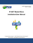
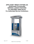
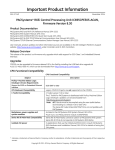
MDE-2713A
Universal Distribution Box Installation Manual
Installation
Purpose of This Document
This document provides installation information for the Universal Distribution Box PA0261.
The distribution box provides an interface between Gilbarco consoles with two-wire current
loop (TWI) interface and dispensing units or G-SITE® controllers with RS-422 interface and
dispensing units, CRIND®s, or G-CAT™s. This distribution box works with all Gilbarco
electronic fuel dispensing consoles and controllers.
This document also provides the installation instructions for the expansion board kit, K93717.
The kit allows you to add a second distribution board to the distribution box.
Important
Do not install this equipment unless you have proper training for installing equipment in a
hazardous location.
Required Documents
The document(s) shown below are referenced by the safety information and/or installation
procedures in this MDE. Make sure that you have these documents available before you begin
the job.
NFPA 30A
NFPA 70
The Automotive and Marine Service Station Code
The National Electric Code
Related Documents
The documents shown below are listed as helpful references. Make sure that you have the
applicable documents available before you begin the job.
FE-xxx
MDE-2072
MDE-2213
MDE-2383
MDE-2398
MDE-2530
MDE-2531
MDE-2537
MDE-2714
MDE-2755
MDE-3110
Field Wiring Diagram for Gilbarco Electronic Dispensers Using the
Gilbarco Distribution Box
Transac 12G Installation Manual
TCR-G/2 Installation Manual
Transac System 1000 Console/Controller Installation Manual
G-SITE Installation Manual (C2)
Pump & Dispenser Installation Manual
Universal Pump And Dispenser Start-Up/Service Manual
PAM 1000 Controller Installation Manual
Universal Distribution Box PA0261Service Manual
Gilbarco STP Control and Dispenser Isolation Relay Box Installation
Manual
PC G-SITE Installation Manual
Superseded Documents:
The document shown below is superseded by this document:
MDE-2798
Notice for Universal D-Box Jumper Setting
MDE-2713A • Universal Distribution Box • 09/99
Page 1
Parts
Parts
Expansion Kit (K93717)
Description
Part Number
PCB Distribution box assembly
T17651 G1
Quantity
1
Expansion cable assembly
R19262 G1
1
Cable assembly, J905 to J102
R18810 G1
1
PCB supports
Q10651 02
4
Standoff Male/Female for J905
Q10437 07
2
Cable assembly MTA-Pigtails
R19263 G1
2
Cable assembly, J103 to J905
R19249 G1
1
Related Kits
K93391-01
R18879-01
Pigtail Cable Kit for Transac System 1000 and PAM 1000 installation
using field wiring to connect to D-Sub connectors for TWI inputs. Not
for use with G-SITE®.
Two-Wire Cable for connecting TCR-G/2 or Transac 12G to Universal
Distribution Box.
Recommended Tools
•
•
•
•
•
•
Page 2
drill
multimeter
needle nose pliers
screwdriver, slotted and Phillips
wire nuts
wire stripper
MDE-2713A • Universal Distribution Box • 09/99
Safety Symbols
Safety Information
Read NFPA 30A and NFPA 70
(U.S. Installations)
Before installing the equipment, the installer must read, understand and follow this manual,
NFPA 30A, NFPA 70, and applicable federal, state and local codes and regulations. Failure to
do so may adversely affect the safe use and operation of the equipment.
CSA C22.1 (Canadian Installations)
For installation in Canada the installer must read and understand this manual, CSA C22.1
(Canadian Electrical Code) and applicable federal, provincial and local codes and regulations.
Safety Symbols
Alert Symbol
This is a standard alert symbol. When you see this symbol, along with the following signal
words in Gilbarco manuals, be alert to the potential for personal injury.
Signal Words
The following Signal Words are used throughout this manual to alert you of important safety
hazards.
!
WARNING
The hazard or unsafe
practice may result in
severe injury or death.
!
CAUTION
The hazard or unsafe
practice could result in
minor injury or
damage to equipment.
!
DANGER
The hazard or unsafe
practice will result in
severe injury or death.
Safety Symbols
OFF
The above safety symbols are used in Gilbarco manuals to alert you to important safety
hazards and precautions.
Fuel and Vapors
Because this equipment is installed in an environment with fuel and fuel vapors, there is a risk
of fire and explosion. Ensure safety devices are installed and adequate precaution taken to
minimize the possibility of danger and risk of severe injury or death.
MDE-2713A • Universal Distribution Box • 09/99
Page 3
Safety Symbols
Emergency Power Cutoff
NFPA30A and Gilbarco require that an emergency power cutoff be installed. An emergency
power cutoff is a single control that removes AC power from all site fueling equipment and
submerged turbine pumps (STPs). Make sure the control is accessible, labeled clearly, and
installed away from dispensers. Make sure all station employees know where the Emergency
Power Cutoff is located and how to operate it.
WARNING - Do not use E-STOP, ALL-STOP, or PUMP STOP keys on Gilbarco consoles/
cash registers to shut off power. These keys do not remove AC power and do not always stop
product flow.
Remove power before replacing boards. Turn off circuit breakers to the unit being serviced.
Electrical Circuits
Some of the procedures in this manual involve removal and connection of components during
installation or service. Remove power from the distribution box before executing these
procedures.
Low Voltage
Do not be misled by the term “Low Voltage”. Voltage potentials as low as 50 volts may cause
death under adverse conditions.
High Voltage
High voltage of 115 to 230 volts AC is used for operation of this equipment. Death on contact
may result if safety procedures are not followed.
Working Alone
It is highly recommended that someone who is capable of rendering first aid be present. Be
familiar with Cardiopulminary Resuscitation methods if you are working with or around high
voltages. This information is available from the American Red Cross.
Electrostatic Discharge Damage
Working on console electronics without connecting to a ground or discharging static can
damage electronic parts. Use a wrist strap and store parts in antistatic storage bags.
Page 4
MDE-2713A • Universal Distribution Box • 09/99
Overview
Installation
Overview
The distribution box provides an interface between Gilbarco consoles with two-wire current
loop (TWI) interface and dispensing units or G-SITE® controllers with RS-422 interface and
dispensing units, CRIND®s, or G-CAT™s. The printed circuit board(s) inside the distribution
box includes jumper jacks which are used to select either the TWI or the RS-422 configuration.
The required interface connector(s) to the controller is provided, and is based on which model
distribution box you have.
Note: Interface cables between the distribution box and the console/controller are not
included, and must be ordered separately. See “Data Cabling Requirements” on
page 12 for proper length and type of cable required.
The distribution box houses the power supply transformer and a removable tray with either one
or two printed circuit boards. Each printed circuit board contains a power supply, an optocoupled current loop interface, an RS-422 interface, eight dispenser current loops, and
automatic isolation circuitry.
Two four channel MTA (Mass Terminal Assembly) connectors are provided for each circuit
board for field wiring. (See Figure 6).
The Transac System 1000TM and PAM 1000 controllers require this distribution box. One
distribution box is needed for every 12 fueling positions. (Transac System 1000™ systems
with three or four consoles require an additional distribution box)
Distribution Box - Controller Interface
There are eight individual current data loops for dispensing units on each distribution board.
(See Figures 1 - 4) When two boards are installed in a distribution box, they can be configured
as either:
• Two separate inputs with each input controlling eight (8) data loops. (See Figure 1C or
2C), or
• One input controlling sixteen (16) data loops. (See Figure 1B or 2B).
Each data loop has both current regulation and automatic isolation circuitry. The dispenser
data loop drivers operate from an unregulated 12 volts DC supply at 45ma for Gilbarco
dispensers and CRIND®s, or 20ma for G-CAT™s. The applicable configuration is set by jump
jacks on the distribution board(s). (See Figures 7-13).
Each distribution board must be dedicated for use with either Gilbarco dispensing units,
CRIND®s, G-CAT™s, or consoles (for Transac System 1000™ multiple consoles). Do not mix
different current loop equipment on one distribution board.
When installing equipment, ensure that the boards are configured for 20ma current loops if
connecting G-CAT™s to the distribution box. Damage to the G-CAT MPU boards will occur if
the jump jacks are not set correctly.
When installing equipment, connect only one dispenser or card reader to any one data loop
channel. The wiring length between the distribution box and dispensers is not to exceed 2600
feet, and requires stranded or solid 14AWG wire. Do not use daisy chaining with this unit.
For Transac System 1000 multiple console installation, refer to MDE-2538 Pigtail Cable Kit
Instructions.
MDE-2713A • Universal Distribution Box • 09/99
Page 5
Distribution Box Configurations
Distribution Box Configurations
The following illustrations show the various distribution box interface configurations.
1A
Up to 8 Duals or 8 Single-Sided Dispensers
TS 1000
PAM 1000
PAM
PC
Board
TCR-G2
T-12G
Distribution-Box
Console/Controller
Note: Refer to console installation manual for
maximum number of fueling positions allowed.
One Board
One Input
Up to 8 Duals or 16 Single-Sided Dispensers
1B
PC
Board
TS 1000
PAM 1000
PAM
PC
Board
TCR-G2
T-12G
Distribution-Box
Console/Controller
Note: Refer to console installation manual for
maximum number of fueling positions allowed.
Two Boards
One Input
Up to 8 Duals or 8 Single-Sided Dispensers
Up to 8 Duals or 8 Single-Sided Dispensers
1C
PC
Board
PC
Board
Distribution-Box
TS 1000
PAM 1000
PAM
Console/Controller
Note: Refer to console installation manual for
maximum number of fueling positions allowed.
Two Boards
Two Inputs
R0000200
Figure 1. TWI Consoles and Controllers
Page 6
MDE-2713A • Universal Distribution Box • 09/99
2A
Up to 8 Duals or 8 Single-Sided Dispensers or 8 Dual CRIND®s
G-SITE®
PC
Board
Distribution-Box
Console/Controller
One Board
2B
One Input
Up to 8 Duals or 16 Single-Sided Dispensers or 16 Dual CRIND®s
PC
Board
PC
Board
G-SITE®
Distribution-Box
Console/Controller
Two Boards
2C
One Input
Up to 8 Duals or 8 Single-Sided Dispensers
or 8 Dual CRIND®s
PC
Board
PC
Board
Distribution-Box
Two Boards
Up to 8 Duals or 8 Single-Sided
Dispensers or 8 Dual CRIND®s
G-SITE®
Console/Controller
Two Inputs
R0000200
Figure 2. G-SITE® With Dispensers
MDE-2713A • Universal Distribution Box • 09/99
Page 7
Up to 8 Duals or 8 Single-Sided Dispensers
or 8 Dual CRIND®s
PC
Board
Up to 4 G-CATTMS
G-SITE®
PC
Board
Distribution-Box
Console/Controller
Two Boards
Two Inputs
R0000202
Figure 3. G-SITE® With Dispensers and CRIND®s Or G-CAT™s
Up to 8 Duals or 8 Single-Sided
Dispensers or 8 Dual CRIND®s
PC
Board
Up to 8 Duals or 8 Single-Sided
Dispensers or 8 Dual CRIND®s
G-SITE®
PC
Board
Distribution-Box
Console/Controller
Up to 4 G-CATTMS
PC
Board
Distribution-Box
R0000203
Figure 4. G-SITE® With Dispensers, CRIND®s, And G-CAT™s
Page 8
MDE-2713A • Universal Distribution Box • 09/99
Model Number Breakdown
Model Number Breakdown
PA0261X00X0XX
Model Number Prefix
Voltage
Not Used
Housing
Not Used
Number of Boards
Data Input
PA0261
Universal distribution box
0 - 115VAC 50/60 Hz
1 - 230 VAC 50/60 Hz
00
0 - Standard
1 - Europe
0
1 - One PCB (8 loops)
2 -Two PCBs (16 loops)
0 - Two-wire
1 - RS-422
Configurations
Model
PA0261X000010
Interface
#Boards
TWI
# Inputs
1
1
Factory Configured As
See Figures 1A & 7
PA0261X000020
TWI
2
2
See Figures 1C & 9
PA0261X000011
RS422
1
1
See Figures 2A & 10
PA0261X000021
RS422
2
2
See Figures 2C & 12
Specifications
Dimensions
Height:
7 and 13/16 inches
Width:
16 and 9/32 inches
Depth:
5 and 15/32 inches
Weight:
5 pounds
Dedicated Isolated Ground Receptacle
USA/Canada
115 volts AC nominal, 50/60 Hz
International
230 volts AC nominal, 50/60 Hz
Current
0.5 amp @ 115VAC
0.25 amp @ 230 VAC
Operating Environment
Minimum Temperature
+32°F (0°C)
Maximum Temperature
+130°F (+55°C)
Humidity
5-95% Rh (non-condensing)
MDE-2713A • Universal Distribution Box • 09/99
Page 9
Preliminary Preparation
Preliminary Preparation
Unpacking Equipment
When the equipment arrives at the installation site, each unit should be unpacked and inspected
for possible shipping damage. If damage is evident, it must be reported to the carrier. Shipping
damage is not covered under Gilbarco’s warranty policy. After visual inspection, place the unit
back in its shipping carton to prevent undue exposure to the elements, and store indoors until
ready for installation.
Return of Components
Components returned to Gilbarco under warranty or for repairs are subject to severe shipping
damage if not packaged properly. If original packing materials are unavailable, use a durable
reinforced corrugated box and obtain suitable packing material such as “PAKON” polyfoam
chips, polyurethane foam chips, or polystyrene foam chips. Fill bottom of box with at least 2
inches of packing material. Make certain the component is firmly packed. It is also
recommended that the package be fully insured.
All returned items must be accompanied by a Returned Goods Authorization (RGA) form.
Remember to include return shipping information and a description of the malfunction.
Note: If the component arrives at Gilbarco in a damaged condition and it is ascertained that
the damage was a direct result of improper packing, such damage will not be covered
under the original factory warranty and the customer will be held responsible for the
cost of the repair necessary to correct said damage.
Basic Site Criteria
Installation of the distribution box must be in accordance with the National Electrical Code
NFPA 70, the Automotive and Marine Service Station Code NFPA 30A, and any state or local
electrical requirements.
For Canadian installations use the Canadian Electrical Code CSA C22.1.
The site must be equipped with electric service allowing compliance with all installation
requirements of a complete fueling system.
An enclosed weather-protected structure must be located on the site for housing the
distribution box. Room ambient temperature must not exceed 130°F (55°C). This maximum
temperature is allowed only if the equipment is allowed free air flow.
Megger testing of field wiring must be completed prior to connecting wires to the distribution
box.
The data cabling between the distribution box and the system controller must be kept separate
from all other power and control lines.
Physical Placement
Locate the distribution box in an area not subjected to extreme temperature variations. The
ambient temperature must remain relatively constant. Do not install the distribution box in a
position subject to direct sunlight. If conditions so dictate, provide a suitable sunscreen.
The PA0261 distribution box is suitable for use over hazardous locations. The box must be
installed at least eighteen inches above the floor. Locate the distribution box in an area which
minimizes the possibility of liquids being spilled onto it.
Allow several inches clearance on the left side of the distribution box for the AC power cord.
Allow two inches clearance above the box for removing the cover.
Page 10
MDE-2713A • Universal Distribution Box • 09/99
Electrical Wiring Requirements
The receptacle providing power to the distribution box must be a properly installed isolated
ground receptacle (Hubbell #IG5261 or equivalent). This type receptacle is easily identified by
its bright orange color and by the triangle embossed into the face of the outlet. The green
grounding screw must be attached to the grounding conductor.
• All electrical wiring must conform to National Electrical Code (NEC) and local wiring
codes, as well as the criteria in this manual.
• One conduit from the breaker panel to the distribution box location is required. The
conduit must contain three 14 AWG wires: 115VAC Hot, Neutral, and Ground; or
230VAC L1, L2, and Ground. Do not use the electrical conduit to provide earth ground.
• The circuit powering the distribution box must not power other devices. This circuit
must not share a conduit with wiring for devices drawing high amperage (compressor,
freezer, etc.) or devices that are sources of RFI (TV, microwave, intercom, etc).
• The AC outlet must be within six feet of the distribution box. (See Figure 5). Do not use
extension cords.
Note: For 230VAC operation, a nine foot detachable line cord is provided. It is the customer’s
responsibility to supply a plug for the cord, that meets local electrical codes and UL
requirements.
MDE-2713A • Universal Distribution Box • 09/99
Page 11
Data Cabling Requirements
Refer to the table that follows for the correct controller to distribution box data cable.
Interface
Controller
Cable Part #
Cable Length
TWI
PAM 1000 or Transac
System 1000TM
Q11542-52
10 feet
TWI
PAM 1000 or Transac
System 1000
Q11542-53
50 feet
TWI
PAM 1000 or Transac
System 1000
Q11542-54
100 feet
TWI
PAM 1000 or Transac
System 1000
K93391-01
pigtail cable kit (use with 14ga field wiring to
extend to 2600’ maximum
TWI
TCR-G or G2
R18879-01
10’ (adapts TCR output to DB9 connector)
TWI
Transac 12G Console
R19000-02
6’ (use with 14ga field wiring to existing channel
on PA0133 distribution box)
RS-422
G-SITE®
R17963-01
25 feet
RS-422
G-SITE
R17963-02
16.5 feet
RS-422
G-SITE
R17963-03
6.5 feet
RS-422
G-SITE
R17963-04
50 feet
RS-422
G-SITE
R17963-05
100 feet
RS-422
G-SITE
R17963-06
gender-mender to extend cabling
Install all cables so that they are protected from damage or accidental disconnection. Route the
cables along a wall or under a counter and secure with cable ties or suitable cable clamps.
Do not route data wires over fluorescent light, compressor wiring, etc., or near other sources of
interference.
Console/Controller
Cables
Line Cord
Q11121-01
115VAC
One inch conduit knock-outs (3) are
provided on bottom for field wiring.
Line Cord
Q11736-02
230VAC
Q11736-02 (User to supply
proper plug for 230VAC.)
R0000205
Isolated Receptacle. User to supply proper receptacle to meet local electrical code requirements. The
receptacle providing power to the PA0306 must be a properly isolated ground receptacle (Hubbell #IG
5261 or the equivalent). The green grounding screw must be attached to the grounding conductor
Figure 5: Cable Requirements
Page 12
MDE-2713A • Universal Distribution Box • 09/99
Field Wiring Requirements
A wiring trough will be required in the vicinity of the distribution box for terminating the
conduit runs from the dispensers. Three one inch knockouts are provided on the bottom of the
distribution box for running conduit between the box and the wiring trough.
Use 14AWG stranded wire for data wires to Gilbarco dispensing equipment. Leave plenty of
wire exposed as a service loop in the wiring trough. Sixteen inches of exposed wire will be
needed inside the distribution box.
When pulling wires, be careful to avoid damage to the insulation.
MDE-2713A • Universal Distribution Box • 09/99
Page 13
Installation Procedure
Installation Procedure
Use the following procedure to correctly install the distribution box.
1 Loosen two screws on bottom front of distribution box and lift lid.
2 Carefully remove and discard any packing material from distribution box.
3 Disconnect cable from the distribution board(s) at P101 and P102 (or P103). Disconnect
wiring pigtails from P106 and P107. See Figure 8 for connector locations.
!
CAUTION
Working on printed circuit
boards without connecting to a
ground or discharging static
can damage electronic parts.
Use a wrist strap and store
parts in antistatic storage
bags.
4 Slide mounting tray (with circuit board(s)) up and out of the distribution box.
Note: The boards are removed to avoid unnecessary damage to components while
mounting the unit to the wall.
5 Mount distribution box to the wall.
• Allow clearance on left side to connect AC cable.
• Allow clearance above the distribution box so that the cover can be removed.
6 Mount AC receptacle within six feet of the distribution box.
7 Install conduit for data wires between the wiring trough and the distribution box. Pull data
wires up into the distribution box leaving sixteen inches of wire inside the distribution box.
This allows for easy installation of wiring pigtails.
8 Connect data wires to wiring pigtails (See Figure 6).
9 Replace mounting tray (with circuit board(s)). Reconnect P101, P102 or P103, P106, P107
as required to the circuit board(s).
10 Connect data cable(s) to 9 pin D Sub connectors. Plug MTA Pigtails to the circuit
board(s).
Page 14
MDE-2713A • Universal Distribution Box • 09/99
Installation Procedure
11 Verify that the jump jack settings are correct for your configuration. Refer to Table 1
below for correct jump jack configuration:
Note: When installing the universal distribution box for a RS-422 application (G-SITE®),
jump jack JP9 must be installed for the correct hardware configuration. Configure
jump jack JP9 for 45ma current loop for CRIND®s/dispensers and 20ma for use with
G-CAT™ 2 and G-CAT 3.
Table 1 - Jump Jack Configuration
Configuration
1 Board/1 Input
2 Boards/2 Inputs
2 Boards/2 Inputs
TWI: Dispensers
Figure 7
Figure 8
Figure 9
RS422: Dispensers or CRINDs
Figure 10
Figure 11
Figure 12
RS422: 8 Dispensers, 8 CRINDs
Figure 12
RS422: 8 Dispensers or CRINDs,
4 G-CAT™s
Figure 13
RS422: 4 G-CAT™s
Figure 14
12 Plug in AC power cord.
13 Change jump jacks (JP1-JP8) one at a time to the NORMAL position. Verify operation of
card readers and/or dispensing units.
14 Replace distribution box cover and secure with screws.
Wire Nuts
Cut and strip supplied loops for desired number
of field connections.
14 AWG Field Wiring
R19263 Pigtail Cable Assembly
If unused pigtail loops are cut, the exposed
ends must be capped with wire nuts.
R0000206
Figure 6: Field Wiring to MTA Pigtails
MDE-2713A • Universal Distribution Box • 09/99
Page 15
To
Dispensers
To
Dispensers
P106
To Controller
9-pin D-Sub
P101
R0000227
To
Transformer
Wire Nut to Field Wiring
P107
Note: This configuration interfaces with all TWI consoles/controllers
Figure 7. Jumper Settings - TWI Interface, Single Board, Single Input, 8 Loops
Page 16
MDE-2713A • Universal Distribution Box • 09/99
To
Dispensers
P106
Board 2
To
Dispensers
Wire Nut to Field Wiring
P107
P101
To
Dispensers
Board 1
P106
To
Dispensers
Wire Nut to Field Wiring
P107
R0000219
To
Transformer
To Controller
9-pin D-Sub
P101
Note: This configuration interfaces with all TWI consoles/controllers
Figure 8. Jumper Settings - TWI Interface, Dual Board, Single Input, 16 Loops Total
MDE-2713A • Universal Distribution Box • 09/99
Page 17
R0000221
Page 18
Board 1
To
Dispensers
P106
To Controller
9-pin D-Sub
To
Transformer
To
Dispensers
Wire Nut to Field Wiring
To Controller
9-pin D-Sub
Board 2
To
Dispensers
To
Dispensers
Wire Nut to Field Wiring
P107
P106
P101
P107
P101
Figure 9. Jumper Settings - TWI Interface, Dual Board, Two Input of 8 Loops Each
MDE-2713A • Universal Distribution Box • 09/99
To Dispensers
or CRIND®s
P106
To G-SITE® Controller
9-pin D-Sub
To Dispensers
or CRIND®s
Wire Nut to Field Wiring
P107
R0000222
To
Transformer
P101
Figure 10. Jumper Settings - RS-422 Interface, Single Board, Single Input, 8 Loops
MDE-2713A • Universal Distribution Box • 09/99
Page 19
R0000223
Page 20
Board 1
To Dispensers
or CRIND®s
P106
P101
To G-SITE® Controller
9-pin D-Sub
To
Transformer
To Dispensers
or CRIND®s
Wire Nut to Field Wiring
Board 2
To Dispensers
or CRIND®s
To Dispensers
or CRIND®s
Wire Nut to Field Wiring
P107
P106
P101
P107
Figure 11. Jumper Settings - RS-422 Interface, Dual Board, Single Input, 16 Loops Total
MDE-2713A • Universal Distribution Box • 09/99
R0000224
MDE-2713A • Universal Distribution Box • 09/99
Board 1
To Dispensers
or CRIND®s
P106
P101
To G-SITE® Controller
9-pin D-Sub
To
Transformer
To Dispensers
or CRIND®s
Wire Nut to Field Wiring
P101
To G-SITE® Controller
9-pin D-Sub
Board 2
To Dispensers
or CRIND®s
To Dispensers
or CRIND®s
Wire Nut to Field Wiring
P107
P106
P107
Figure 12. Jumper Settings - RS-422 Interface, Dual Board, Two Inputs of 8 Loops Each
Page 21
CAUTION
Board 2
This jumper must be set
correctly to interface to
G-CAT™s. Serious
damage will result to the
G-CAT if it is incorrectly
set.
To G-SITE Controller
9-pin D-Sub
P106
To G-CAT™s
Wire Nut to Field Wiring
!
Board 1
To Dispensers
or CRIND®s
P106
To G-SITE Controller
9-pin D-Sub
To Dispensers
or CRIND®s
Wire Nut to Field Wiring
P107
R0000225
P101
Figure 13. Jumper Settings - RS-422 Interface, Dual Board, One Input Dispenser or CRIND®s (8 Loops)
and One Input G-CATTM (4 Loops)
Page 22
MDE-2713A • Universal Distribution Box • 09/99
!
CAUTION
P106
R0000226
To G-SITE® Controller
9-pin D-Sub
To G-CAT™s
Wire Nut to Field Wiring
This jumper must be set
correctly to interface to
G-CAT™s. Serious
damage will result to the
G-CAT if it is incorrectly
set.
Figure 14. Jumper Settings - RS-422 Interface, Single Board, Single Input, G-CATTM to G-SITE® System
MDE-2713A • Universal Distribution Box • 09/99
Page 23
Installation Instructions for Expansion Kit K93717
Installation Instructions for Expansion Kit K93717
This kit provides the necessary parts to convert a single-board distribution box (PA0261) to a
dual-board, single or dual input unit.
1 Remove AC input power to distribution box.
2 Loosen the two screws on the top cover. Slide top cover up to remove it from the bottom
housing.
3 Remove P101, P102 or P103, P106 and P107 from the existing distribution board.
4 Slide mounting tray (with circuit board) up and out of the distribution box.
5 Install the four standoffs supplied from kit into the holes provided on the mounting tray as
shown in Figure 9.
6 Install the new distribution board on the standoffs. Make sure that the new distribution
board is oriented in the same manner as the original distribution board. See Figure 9.
7 Install the expansion cable between the two boards.
8 Set jump jacks for your configuration. Refer to “Table 1 - Jump Jack Configuration” on
page 15
9 Remove knockout in the bottom housing to allow access to the modular jack connector on
the new board. Install the D-Sub input cable (use R19249-G1 for G-SITE® or R18810-G1
for all other controllers).
10 Connect the field wiring to the prewired MTA connector as shown in Figure 7.
11 Reinstall the mounting tray into the guide in the bottom housing. Make sure that the two
input cables are above the tray.
12 Reinstall the connectors removed in Step 3. Install new field wiring connectors P106 and
P107 on newly installed distribution board.
13 Connect new external cable to console or controller if installation is required.
14 Set the NORMAL/ISOLATE jump jack to NORMAL for channels being used.
15 Reapply power and check system for proper operation.
16 Replace top cover and tighten screws.
Page 24
MDE-2713A • Universal Distribution Box • 09/99
Mounting Tray
Q10651-02 (4)
T17651-G1
R19262-G2
R0000208
Figure 15. PCB Mounting to Sheet Metal Plate
MDE-2713A • Universal Distribution Box • 09/99
Page 25
© 1999 Gilbarco, Inc. • 7300 West Friendly Avenue • Post Office Box 22087 • Greensboro, North Carolina 27420 • Phone (336) 547-5000 • http://www.gilbarco.com
MDE-2713A
09/99
Printed in the U.S.A.