1
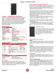
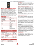
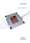
REGIS T – Standalone, access or time and attendance controller
REGIS T – STANDALONE, ACCESS or TIME AND
ATTENDANCE CONTROLLER
The Regis is a controller with built-in proximity card reader and 7”
LCD capacitive touch screen display. It is designed for residential
and business buildings, offices, shops, etc. The controller can have
125kHz or 13.56MHz reading frequency.
As a standalone controller, the entire set-up procedure is carried
out with master card or code. User cards and codes can either be
registered or deleted. The controller allows access for up to 500
users (1 master card + 500 user cards or codes).
As an access controller, the entire set-up procedure is carried out
with the software. The controller allows access for up to 30000
users and saves 100000 events. If you bought the controller in
time and attendance kit, then inputs and outputs cannot be
controlled.
It can also be used as a Wiegand 26-bit reader, if needed.
The SDK is also available for this controller. If a user or software
producer wants to develop its own application, please contact us.
TECHNICAL DATA
REGIS T
REGIS T-1-9-NET reading frequency
125kHz
REGIS T-1-9-NET reading distance
Up to 15cm
REGIS T-1-9-NET current consumption in
300mA
standby mode
REGIS T-3-9-NET reading frequency
13.56MHz
REGIS T-3-9-NET reading distance
Up to 7cm
REGIS T-3-9-NET current consumption in
330mA
standby mode
Dimensions (mm)
210x150x35 (WxHxD)
Protection
IP21
Operating voltage
From 9V to 14V DC
Operating temperature
From -20°C to 60°C
Connector
2x 8pin, 1x ethernet
Display
TFT - capacitive touch
Tamper
Accelerometer
Display resolution
800 x 480
Humidity
10-80%, non condensing
Memory
500 or 30000 cards or codes
100000 events
Inputs
Door status
Push button
Outputs
Transistor output for el. strike
0.5A
Clock
Real time clock, battery backup
(max. ten hours)
Communication
RS485
Ethernet
Keypad
Configurable buttons
Selectable colors
Voltage drops and cable signal interferences
When you connect the controller, use cable with a diameter of at
least 0.22mm2. If the cable length exceeds 25m, use one twisted
pair of UTP cables for the positive (+) pole and one for the
negative (-) pole. The cable length between power supply and the
controller should not exceed 50m.
Take into consideration that a 0.22mm2 cable has a resistance of
approximately 9 ohm per 100m. The power supply at the end of
cable should be a minimum of 9V. If you are using el. strike, it is
highly recommended that the voltage drop is calculated. At greater
distances, a thicker cable of 0.5mm2 or more should be used
wherever possible.
If the load is, for example, 0.5A (with el. strike) then, on the
0.22mm2 cable voltage drop will be 4.5V at 100m. For the device
with 60mA consumption, the voltage drop is 0.5V.
Reading distance depends on where the controller is installed. The
presence of metal or interferences can significantly reduce the
reading distance. DO NOT install the controller directly on metal
surfaces and/or cover it with a metal cover.
It is not recommended to install controllers closer than 30cm
from each other in any direction. Otherwise, it may result in
inaccurate readings or, indeed, in the controller not reading at
all.
For the Regis T-3-9-NET to comply with EMC directives (CE),
you have to put ferrite core on the cable as close to the
controller as possible, making two turns!
CONNECTOR DESCRIPTION
Connectors are marked on the housing
with 1 in 2. First contact on both
connectors starts on the marked side (1
and 2)
CONNECTOR 1 – connection of power supply, el. strike...
Contact
Description
Specification
1
9-14V DC
Power supply
2
GND
Ground
Max. 0,5A
3
El. strike output
Active = GND
Max. 0,5A
4
Alarm output
Active = GND
5
Door status switch input
Active = GND
6
Push button input
Active = GND
7
CA
RS485 A line
8
CB
RS485 B line
CONNECTOR 2 – connection of external reader
Contact
Description
Specification
1
9-14V DC
Power supply
2
GND
Ground
3
Data 0
Wiegand protocol
4
Data 1
Wiegand protocol
5
Buzzer output
Active = GND
6
LED output
Active = GND
7
XA – for protocol reader
RS485 XA line
8
XB – for protocol reader
RS485 XB line
*if Regis T is in Spider mode, the same data applies
Power supply
The controller need’s external power supply to operate. The Spider
W40 power supply is sufficient to power two controllers and two
12V electric strikes or two 12V magnetic locks (0.5A). If you will
use it as a standalone controller and low consumption electric
strike (0.25A) you can use power supply Spider W5.
5/2014
Black line
www.jantar.si
REGIS T – Standalone, access or time and attendance controller
Inputs, outputs and environment
Inputs:
Inputs are realized with opto-isolators. The input is active, when
pulled to ground with an open collector transistor or mechanical
switch, which is connecting the input pin of the controller to the
Ground.
Outputs:
Output has a pre-installed protection diode for an inductive load. It
is also protected from current overload. The best way is to use a
0.25A el. strike or a 0.5A el. magnet, which has to be connected to
the same positive pole (+) as the controller. Connect the negative
pole (-) to the door strike output (wire 3). When the output is
active it is pulled to ground. This can be changed with function 5 –
negate output (for el. magnet).
Environment:
Do not install the controller on/in a place, where it can come in
contact with water. You must assure good cable joints, protected
against moisture, otherwise corrosion may damage the controller.
Damage in such cases is not covered by the warranty.
Regis T-1-9-NET reading range:
The controller has a program algorithm that, at power start, sets
parameters based on the installation environment, so as to ensure
an optimal reading range. DO NOT install the controller directly on
metal surfaces and/or cover it with a metal cover; it may stop
working/reading. If you plan to test the controller and move it onto
different surfaces, then you have to reset it (power off/on) on each
surface.
ACCESS OR TIME AND ATTENDANCE
CONTROLLER
Access controller
As an access controller, it is intended for controlling entries, exits
and passes of users in the system and controlling sliding doors,
ramp, el. strike, turning alarm on/off… It needs to be set with V7
or CODEKS software.
Time and attendance controller
As a time and attendance controller, it is intended to register the
employee’s arrivals and exits from work, lunch break, private and
business exits, sick leave... It needs to be set with V7 or CODEKS
software. In software you need to choose option “Time and
attendance” for controller and reader. Set the software according
to your requirements (time tables, users...) and send the tables.
The keypad will serve for choosing different time intervals (private,
business…).
The controller switches to access or time and attendance
controller when tables are sent by the software or when it is
set to mode 4 with function 9. Change the controller’s
address from 255 to any number between 1 and 254. If you
have more controllers on the communication line, don’t
duplicate addresses. Add them one by one on the
communication line, because every controller has address
255 by default.
Communication
Ethernet:
Connect the controller to the computer through your LAN via
Ethernet connector. Use at least UTP CAT 5e cable. Adjust network
settings of the controller using the Codeks Device Manager
software so that it will function properly in your network. Please
consult Codeks Device Manager manual.
S - Spider mode
In the Spider mode the controller can be used as a communication
converter, from which you can continue RS485 communication line
to the other controllers. When the controller is reset to the factory
settings (brainwash), the controller address is set to 254.
RS485:
Connect the controller to the computer, with one of the power
supplies, with communication converter, from the Spider family:
Spider W5-USB, Spider W5-NET, Spider W40+NET.
The RS485 communication bus is used between the controllers and
Jantar software. Up to 128 controllers can be lined up into one
communication line. The maximum length of the communication
line is 1000 cable meters. It is recommended that you use an FTP
or S-FTP cable. Only a serial connection of controllers in a single
communication line is allowed. Star (parallel) connection is not
allowed.
All shields of S-FTP cables must be wired together and at one
point connected to the earth. Individual connections to the earth
are not allowed. Do not connect the shield of the cable to the
ground of the controller.
In the event of problems in communication, a termination
resistor needs to be added. We recommend using 120 Ohm
resistors on each side of the cable. Converters are, on the
RS485 side, protected with slow-blow fuses and transient
voltage suppressors.
Reset to the factory settings (brainwash):
When the controller is reset to the factory settings (brainwash), the
controller address is set to 254.
ORDERING CODES
REGIS [box]-[card]-[software]
Box:
T
Card:
1 – reading frequency 125kHz (cards)
3 – reading frequency 13.56MHz (cards)
Software: 9 – BLOCKER, CODEKS (support for V7
min.7.995.6.1027)
Communication: NET – Ethernet connection
Communication mode: S – Spider mode
Code
REGIS T-1-9NET
REGIS T-1-9NET-S
REGIS T-3-9NET
REGIS T-3-9NET-S
Description
Standalone or access controller in T box,
Frequency 125kHz, for BLOCKER, CODEKS
or programs from V7 version, Integrated
Ethernet
Standalone or access controller in T box,
Frequency 125kHz, for BLOCKER, CODEKS
or programs from V7 version, Integrated
Ethernet, Spider mode
Standalone or access controller in T box,
Frequency 13.56MHz, for BLOCKER,
CODEKS or programs from V7 version,
Integrated Ethernet
Standalone or access controller in T box,
Frequency 13.56MHz, for BLOCKER,
CODEKS or programs from V7 version,
Integrated Ethernet, Spider mode
OTHER
Warranty only applies when the controller Regis is used with power
supply or/and communication converter from the Spider family.
Please read through our warranty and disclaimer statements.
Connection scheme and additional support for the use of this
product can be found on:
http://www.jantar.si/forum/en
CONTACT:
Jantar d.o.o.
Kranjska cesta 24
4202 Naklo
SLOVENIA
web: www.jantar.si
mail: [email protected]
5/2014
Black line
www.jantar.si