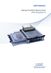
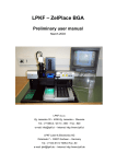
1
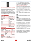
USER MANUAL
LPKF Vacuum Table
Introduction
1Introduction
Company name:
Abbreviated name:
Address:
LPKF Laser & Electronics d.o.o.
LPKF d.o.o.
Polica 33
SI-4202 Naklo
Slovenia
Telephone:
Fax
+ 386 (0) 592 08 800
+ 386 (0) 592 08 820
Internet:
www.lpkf.com
E-mail:
[email protected], [email protected]
Trade-mark:
1.1
LPKF Vacuum Table
The LPKF Vacuum table provides support for rigid and flexible PCBs during printing on the LPKF
ProtoPrint S, and placing of components with the LPKF ProtoPlace S or with LPKF ProtoPlace
BGA. The design of the vacuum table guarantees easy and free movement of the table between
printer and placer without disconnection or interruption of the vacuum. The vacuum table is
equipped with special positioning pins, which ensures repeatability of the PCB position, when
repeated printing is required.
Better linking of the entire SMT process is achieved with the use of a thermo ceramic board
which is available as an option. After the placing process is finished, the thermo ceramic board
is released and moved into the LPKF ProtoFlow S soldering oven together with the PCB.
The LPKF vacuum table provides 100 % support for the PCBs during the entire process of SMT
assembly.
User Manual v1.03
Rev.: 11.03.2014
3
Introduction
1.2Warnings
Copyright© 2011-2012 LPKF d.o.o.
Copying and distributing these instructions in their entirety or in part is only permitted by LPKF
approval in writing.
Note: Data can be altered without prior notice.
Original Instructions
LPKF is not liable for any damage occurring due to improper use of these instructions.
The owner of the LPKF device is obligated to:
•
•
•
•
•
•
Ensure that the device is used only for its intended purpose.
Ensure that the device is used only under the specified operating conditions.
Regularly check safety, and control devices.
Ensure that only authorised and qualified personnel operate the device.
Ensure that all operators of the device have ready access to these instructions.
Ensure that the device always has safety labels in place.
Before opening the packaging, check the »shock sensor« located on the outside of the box. If
the indicator is coloured bright red, DO NOT OPEN THE PACKAGING, but immediately inform
your transport agent!
Remove the packaging and check the general state of the equipment, and check the contents
against the enclosed packing list.
In the event of any damage immediately inform the transport agent!
Before starting-up the device, remove all packaging, which served as protection of the device
during transport, otherwise severe damage could be caused to the device!
Please note: unauthorised repairs or modifications to the equipment will void the warranty!
In case of problems with the machine, please immediately contact us, giving the serial number
of the machine!
Telephone:
+ 386 (0) 592 08 800
Fax:
+ 386 (0) 592 08 820
E-mail:
4
[email protected]
[email protected]
Rev.: 11.03.2014
LPKF Vacuum Table
Contents
2Contents
1Introduction
1.1
LPKF Vacuum Table
1.2Warnings
3
3
4
2Contents
2.1
Symbols etc. used in this manual
2.1.1 Registered trademarks
5
7
3
Basic data
3.1Name and address of the manufacturer
3.2
Relevant model
3.3
Intended use
3.4
Technical data
3.5Noise level/vibration/emission of hazardous chemicals
8
8
8
8
8
9
4
Safety notes
4.1
General
4.2Hazards
4.3
Safety measures
4.4
Procedures in the event of injury or other emergencies.
10
10
10
11
11
5Device description
5.1
Basic parts
5.1.1Housing
5.1.2 Supporting plate
5.1.3 Vacuum pump
5.1.4 Air flow regulator
5.1.5 Air valve
5.1.6 Rubber sealant
5.1.7 Positioning pins
5.2
Extra equipment (option)
5.2.1 Vacuum Pump (option)
5.2.2 Thermo ceramic board
5.2.3 Air supply unit (option)
12
12
6Installation
6.1Opening the packaging
6.2
Air connection
6.3
Installation on LPKF ProtoPrint S
6.4
Installation on LPKF ProtoPlace S
6.5
Installation on LPKF ProtoPlace BGA
6.6
Inserting the thermo ceramic upper plate into an oven
17
17
17
18
19
20
21
7
7.1
7.2
7.3
22
22
22
23
Instructions for use
Restricting the area of the Vacuum Table
Reduction of air consumption
Use of the LPKF Vacuum Table
7.3.1Preparation
7.3.2Use
8Maintenance
8.1Cleaning of the Vacuum Pump
8.2Cleaning of the Vacuum Table
User Manual v1.03
Rev.: 11.03.2014
14
24
24
24
5
Contents
9
Troubleshooting
25
10Appendices
10.1 Scope of delivery
6
26
26
Rev.: 11.03.2014
LPKF Vacuum Table
Contents
2.1
Symbols etc. used in this manual
Text in italics emphasises the importance of the information.
Symbols that you will notice in some chapters have the following meaning:
Danger!
The symbol is used to highlight danger to life or health.
Caution!
The symbol warns of circumstances that could threaten the safety and health of the
device operator or cause a serious device defect.
Good advice and instruction
“Rapido” warns us of possible faults, and recommends simple and effective
solutions.
2.1.1
Registered trademarks
The LPKF logo and all LPKF product brand names are registered trademarks of LPKF Laser &
Electronics AG and LPKF Laser & Electronics d.o.o.
All other trademarks are property of their respective owners.
User Manual v1.03
Rev.: 11.03.2014
7
Basic data
3
Basic data
3.1
Name and address of the manufacturer
Company name:
Abbreviated name:
Address:
LPKF Laser & Electronics d.o.o.
LPKF d.o.o.
Polica 33
SI-4202 Naklo
Slovenia
Telephone:
Fax
+ 386 (0) 592 08 800
+ 386 (0) 592 08 820
Internet:
www.lpkf.com
E-mail:
[email protected], [email protected]
Trade-mark:
3.2
Relevant model
LPKF Vacuum Table
3.3
Intended use
The LPKF vacuum table is used for fast and easy clamping of rigid and flexible PCBs. It can be
used on the LPKF ProtoPrint S, on the LPKF ProtoPlace S and on the LPKF ProtoPlace BGA.
If the thermo ceramic board option is purchased, it can also be used with the LPKF ProtoFlow
oven. The vacuum table guarantee simple linking up of the entire SMT assembly process.
3.4Technical data
Max. size of PCB
Max. feed pressure
Operating feed pressure
Optimum feed pressure
Air consumption
Air consumption at optimum feed pressure
Vacuum
Dimensions (W x L x H)
Weight
Ambient conditions
8
230 x 297 mm (9” x 11.7”)
7 bar (0.7 MPa)
1.7 - 6 bar (0.17 - 0.6 MPa)
3 bar (0.3 MPa)
0.3 - 0.8 l/s
0.5 l/s
0.2 bar (0.02 MPa)
270 x 297 x 22.5 mm (10.6” x 11.7” x 0.9”)
4 kg (8.8 Ibs)
Temperature: -10 - +50 ºC (14 - 122 ºF)
Rev.: 11.03.2014
LPKF Vacuum Table
Basic data
3.5
Noise level/vibration/emission of hazardous chemicals
The noise and vibration levels of the device during operation are not harmful to health.
Contact with chemicals (soldering pastes) is possible during work process with the LPKF
Vacuum Table.
Soldering pastes can contain hazardous chemicals.
Verify data on the type of the substance and dangerous characteristics of the
substance on the packaging or on the safety data sheet.
Soldering paste can contain lead!
Please ensure that the prescribed safety measures, stated in the paste manufacturer’s
instructions, are observed. Any advice concerning personal protective equipment
should also be followed!
User Manual v1.03
Rev.: 11.03.2014
9
Safety notes
4
Safety notes
Before using the device, carefully read this chapter on health and safety. Familiarise
yourself with potential risks and prescribed safety precautions.
4.1General
1.
2.
3.
4.
5.
6.
The device must be installed in accordance with the installation instructions.
The device should only be used for its designated purpose.
A suitable working environment must be ensured.
The device may only be operated by qualified personnel.
Servicing can only be performed by authorised and qualified personnel.
Ready access to the “User Manual” must be provided to all device operators.
4.2Hazards
BURNS
There is a risk of burns when taking the thermo ceramics
upper plate out of the oven.
MECHANICAL During operation, a disconnected air hose can cause serious
HAZARDS
injury (direct impact into the body).
10
CHEMICAL
HAZARDS
Soldering pastes can contain substances that are hazardous
to health.
SENSOR
STRESS
In the event of unsuitable general lighting of the area the
operator can experience an increase of sensor stress.
MANUAL
HANDLING
The weight of the device is 4 kg / 8.8 lbs. Dropping the device
could cause serious injury to legs and feet.
Rev.: 11.03.2014
LPKF Vacuum Table
Safety notes
4.3
Safety measures
Before operating the device a full visual inspection should be carried out. In the event of any
defects or malfunctions work must not be started until all faults have been corrected!
It is of vital importance that the area around the device is maintained clean and tidy. A disorganised
work-place can cause occupational injuries (i.e. a person can fall, slip or receive an injury.).
Please ensure that the environment in which the equipment is going to be used conforms to that
specified in this document.
While working with the device the complete attention of the operator is required. A person, who
is feeling unwell or is having difficulties concentrating, should not operate the device!
Only equipment, which has been approved by LPKF can be used in conjunction with the device.
The use of unsuitable equipment could endanger the operator!
Repairs can only be performed by authorised service personnel. These personnel should ensure
that the safety of the equipment is not compromised by the repair.
The storing or consuming of food and drinks in the work area is forbidden!
Smoking is forbidden!
When using hazardous substances, safety data sheet instructions and advice should be followed!
After completing work the device should be turned off (air supply) and cleaned.
Recommended personal protective equipment: protective gloves.
4.4
Procedures in the event of injury or other emergencies.
Emergency disconnection is possible by turning off the power switch.
In the event of a work-related injury, stop the device immediately, and if necessary seek
professional medical assistance.
User Manual v1.03
Rev.: 11.03.2014
11
device description
5Device description
5.1
Basic parts
Support plate
Vacuum pump
Blocking plug
Air flow
regulator
Clamp
Housing
5.1.1Housing
The housing contains the vacuum chamber, and supports and clamps the upper plate. Channels
within the housing enable the size, shape, and position of the vacuum chamber to be adjusted
to suit the PCB. Up to two vacuum pumps can be fitted to the unit.
5.1.2 Supporting plate
The housing contains the vacuum chamber, and
supports and clamps the upper plate. Channels within
the housing enable the size, shape, and position of the
vacuum chamber to be adjusted to suit the PCB. Up to
two vacuum pumps can be fitted to the unit.
5.1.3 Vacuum pump
The vacuum pump is easily upgradeable and replaceable.
Max. efficiency of the vacuum pump is achieved at
3.14 bar (0.314 MPa; see chapter 5.2.1).
12
Rev.: 11.03.2014
LPKF Vacuum Table
device description
5.1.4 Air flow regulator
Air flow regulator, mounted on the housing, regulates
the range of vacuum.
5.1.5 Air valve
The air valve is used for opening and closing the air
supply.
The air valve could be fitted on special holder and placed
near the vacuum table.
5.1.6 Rubber sealant
The rubber seals are designed to increase the efficiency
of the vacuum chamber, reduce the lose of vacuum and
to decrease the evacuation time of the vacuum chamber.
5.1.7 Positioning pins
Insert the position pins into the holes on the upper
support plate to assure the repetition of placement of
the PCB.
User Manual v1.03
Rev.: 11.03.2014
13
device description
5.2
Extra equipment (option)
5.2.1 Vacuum Pump (option)
Use an extra Vacuum Pump to increase the range of created vacuum and better fixation of the
PCB.
Instalation:
1.
Remove the upper support plate out of the housing.
2.
Remove the blocking plug (use the screwdriver):
3.
Remove the extra vacuum pump out of the package:
4.
Install the extra vacuum pump into the housing:
5.
Assemble back the upper support plate:
14
Rev.: 11.03.2014
LPKF Vacuum Table
device description
5.2.2 Thermo ceramic board
A high temperature resistant ceramic plate is an
available option. With this plate, flexible flex prototypes
can be directly transferred into the LPKF ProtoFlow
reflow oven.
This ceramic plate can be used for holding the PCB
through the printing, pick & place, and soldering
processes. After the placing process is finished, the
thermo ceramic board is released from the vacuum
table and moved into the LPKF ProtoFlow soldering
oven together with flex PCB.
The board can be used several times
Use the thermo ceramics plate for printing, placing and soldering flexible PCB’s
Installation:
1.
Release and remove the upper support plate from the
housing:
2.
Insert the thermo ceramics upper plate (option):
3.
Insert the special positioning pins (option) and connect
the air valve to the vacuum table and the air valve in turn
with your air supply unit:
User Manual v1.03
Rev.: 11.03.2014
15
device description
5.2.3 Air supply unit (option)
For easy and reliable air distribution an optional air
pressure regulator with water separator and 5 μm filter
can be mounted on a stand for clamping to the edge of
a table.
16
Rev.: 11.03.2014
LPKF Vacuum Table
installation
6Installation
6.1Opening the packaging
Before opening the packaging, check the »shock
sensor« located on the outside of the cardboard box. If
the indicator is coloured bright red, DO NOT OPEN THE
PACKAGING, but immediately inform your transport
agent!
The picture shows the LPKF Vacuum Table equipped
with an optional vacuum pump and an optional air
supply unit.
6.2
Air connection
1.
Connect the air valve with the Vacuum Table.
2.
Connect the air valve with an air supply unit.
3.
Air supply requirements: 3 - 6 bar (0.3 - 0.6 MPa)
The air valve must be closed before connection
of the air hose to the air supply unit.
4.
Open the air valve:
User Manual v1.03
Rev.: 11.03.2014
17
installation
6.3
Installation on LPKF ProtoPrint S
1.
Place the LPKF Vacuum Table the upper plate of the ProtoPrint S.
2.
Fix the Vacuum Table with the Allen screws enclosed
with the ProtoPrint S.
The Vacuum Table must be placed so that the
vacuum pump is pointing to the right.
3.
Fix the air valve on the side of the ProtoPrint S.
4.
Connect the air valve with the air supply.
5.
Open the air valve.
18
Rev.: 11.03.2014
LPKF Vacuum Table
installation
6.4
Installation on LPKF ProtoPlace S
1.
Place the Vacuum Table on the ProtoPlace S micro-table
so that the channels on the underside of the vacuum
table fit over the rails on the micro-table. The vacuum
pump must be pointed to the right.
2.
Connect the air valve with the air supply unit.
3.
Open the air valve
User Manual v1.03
Rev.: 11.03.2014
19
installation
6.5
Installation on LPKF ProtoPlace BGA
1.
Remove the flexible steel supporting lath from the BGA
Vacuum Table.
2.
Fix the Vacuum Table on the BGA table with two Allen
screws.
3.
Place the air valve on the supporting steel lath of the
BGA table.
4.
Connect the air valve with an air supply unit.
5.
Open the air valve.
20
Rev.: 11.03.2014
LPKF Vacuum Table
installation
6.6
Inserting the thermo ceramic upper plate into an oven
1.
Release the thermo ceramics plate from the housing (release the clamps).
2.
Insert the plate (with the PCB) into an oven:
3.
Start the process of soldering.
After the process of soldering the thermo ceramic upper plate can be hot – risk of
burns! Use protective gloves when removing the plate from the oven.
User Manual v1.03
Rev.: 11.03.2014
21
instructions for use
7
Instructions for use
7.1
Restricting the area of the Vacuum Table
1.
Insert the rubber seals into the grooves in the housing.
2.
Place the PCB on the surface.
3.
Mark the area around the PCB.
4.
Cut the seals where marked.
5.
Place the seals back into the housing.
6.
Replace the upper plate of the Vacuum Table.
7.2
Reduction of air consumption
When the PCB is firmly placed on the upper plate the air
consumption can be reduced by reducing the air supply
with the air flow regulator.
The vacuum pump will provide a sufficient vacuum even
with partially closed speed controller.
22
Rev.: 11.03.2014
LPKF Vacuum Table
instructions for use
7.3
Use of the LPKF Vacuum Table
7.3.1Preparation
1.
Install the Vacuum Table on the machine (ProtoPrint S, ProtoPlace S or ProtoPlace BGA).
2.
Restrict the area of the vacuum table (chapter 7.1).
3.
Connect the air supply hose to the air flow regulator.
7.3.2Use
1.
Place the PCB onto the restricted area.
2.
Insert the Positioning pins.
3.
Lay the PCB upon the pins.
4.
Open the air supply, the vacuum pump is activated and vacuum is created in a few seconds.
5.
Check that there is no venting of the vacuum from the holes surrounding the PCB a reconfigure
the vacuum chamber (chapter 7.1).
6.
Start printing on LPKF ProtoPrint S, or placing on LPKF ProtoPlace S or LPKF ProtoPlace BGA.
User Manual v1.03
Rev.: 11.03.2014
23
maintenance
8Maintenance
8.1Cleaning of the Vacuum Pump
1.
Remove the vacuum pump from the housing and unscrew the vacuum pump. Do not use any
tools!
2.
Remove the filter from the vacuum pump
3.
Soak the filter into a mild cleanser solution and rub it with fingers.
4.
Wash the filter under water.
5.
Dry the filter (use compressed air).
6.
Replace the filter on the vacuum pump.
7.
Screw the vacuum pump into the housing (clockwise rotation). Do not use any tools!
8.2Cleaning of the Vacuum Table
The Vacuum Table is easily cleaned with a damp cloth soaked in a mild detergent solution.
Soldering pastes have to be cleaned in accordance with manufacturers’ instructions regarding
each individual substance.
Most soldering pastes and glues can be cleaned using isopropyl alcohol.
The surface of the oven can be easily cleaned with a soft cloth, soaked in a mild
detergent solution.
24
Rev.: 11.03.2014
LPKF Vacuum Table
troubleshooting
9Troubleshooting
Before any intervention in the device, first disconnect the device from the mains
power system.
In some cases you can correct a fault in device operation yourself following the guidelines stated
below. In the event that you do not succeed do not continue with any repairs, but immediately
contact an authorised serviceman/distributor of LPKF devices.
Fault/Defect
Procedure
Check the vacuum on the air
supply unit.
Check the air hoses.
Check the air valve
Vacuum pump is not working Air supply failure.
(regularity of connection of
air hoses).
Check the speed controller
(must be open).
Vacuum Pump is not working, Vacuum Pump is not fitted
Check the fitting of the
no failure on the air supply.
into the housing properly.
vacuum pump.
The range of air supply is too Check the range of air in the
low.
air supply system.
The vacuum pump filter is
Clean the vacuum pump
stopped.
filter.
The vacuum is too low.
The exhaust of vacuum pump Remove any debris from the
is blocked.
exhaust of the vacuum pump.
Check the clamps holding
Mounting of the upper
the upper support plate to the
support plate failure.
housing.
User Manual v1.03
Cause
Rev.: 11.03.2014
25
Appendices
10Appendices
10.1
Scope of delivery
Air hose, 2 x 2 m
Air valve
Rubber seals, 2 m
Positioning pins, 2 x 3 pcs
User Manual
26
Rev.: 11.03.2014
LPKF Vacuum Table