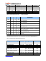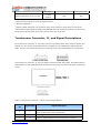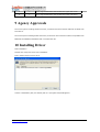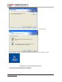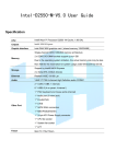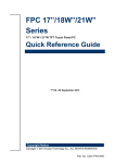
1
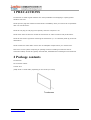
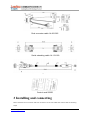
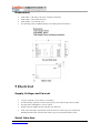
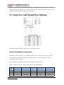
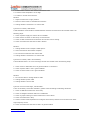
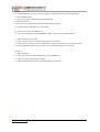
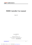
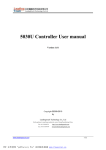
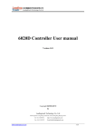
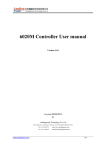
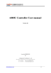
5020D Controller User manual
Version 1.01
Copyright ©2009-2010
by
Leadingtouch Technology Co., Ltd
HuiLongGuan LongXiang industrial center,ChangPing,Beijing,China
www.leadingtouch.com
Tel:+86-51090978
http://www.leadingtouch.com
Fax:+86-51090979
E-mail:[email protected]
1/24
Content
CONTENT ..............................................................................................................................................2
1 PRECAUTIONS ..................................................................................................................................3
2 PACKAGE CONTENTS ....................................................................................................................3
3 INSTALLING AND CONNECTING.................................................................................................4
USB CABLE CONNECTING .....................................................................................................................5
4 PHYSICAL CHARACTERISTICS ...................................................................................................5
CONSTRUCTION .........................................................................................5
DIMENSIONS ............................................................................................6
5 ELECTRICAL.....................................................................................................................................6
SUPPLY VOLTAGE AND CURRENT ......................................................................6
SERIAL INTERFACE ......................................................................................6
BAUD RATE ..............................................................................................7
USB INTERFACE ........................................................................................7
TOUCH RESOLUTION ....................................................................................7
CONVERSION TIME ......................................................................................7
RELIABILITY .............................................................................................7
6 ENVIRONMENTAL ...........................................................................................................................8
TEMPERATURE ...........................................................................................8
HUMIDITY ................................................................................................8
OPERATING ALTITUDE ..................................................................................8
SHOCK AND VIBRATION ................................................................................8
ESD: CONTROLLER ALONE ............................................................................8
7 LED INDICATORS.............................................................................................................................8
8 CONNECTORS AND SIGNAL DESCRIPTIONS...........................................................................9
POWER/INTERFACE CONNECTOR ......................................................................9
TOUCHSCREEN CONNECTOR ......................................................................... 11
9 AGENCY APPROVALS ...................................................................................................................12
10 INSTALLING DRIVER..................................................................................................................12
11 FAQ ...................................................................................................................................................22
www.leadingtouch.com
2/24
1 PRECAUTIONS
Touchscreen is made of glass material. It’s easily breakable from dropping or impact, please
handle it with care.
Please pull the plug and contact the sales dealer immediately when you smell a bit of unpleasant
odor out of touchscreen.
Please do not plug-in and plug-out frequently when the computer is on.
Please clean the front and rear surface of touchscreen in order to make it best performance.
Please do not screw it tight when mounting the touchscreen (i.e. it is desirably fixed up) for fear of
deformation.
Please contact the sales dealer if there are not adequate components to your touchscreen.
New touch screen system comprising of: package contents including touchscreen and PC
connection cables, control card, quality-assured card, installation disc including driver and manual.
2 Package contents
Touchscreen
PC connection cables
Control card
(USB, serial or Comb cable, depending on the model you chose)
Touchsceen
www.leadingtouch.com
3/24
Dual connector cable 14-831-025
Serial extending cable 14-113-180
USB extending cable 14-219-150
Control card 5020D
3 Installing and connecting
Mount touchscreen on monitor and then connect it to PC with cable and control card as following
steps
www.leadingtouch.com
4/24
Serial cable connecting
1. Connect touchscreen 5pin port to 5pin connector of control card.
2. Connect dual connector cable 14-831-025 20 pin connector to 20pin connector of control card.
3. Connect serial extending cable 14-113-180 DB9 male connector to DB9 female connector of
dual connector cable 14-831-025.
4. Connect serial extending cable 14-113-180 DB9 male connector to PC DB9 female port.
5.
Connect dual connector cable 14-831-025 4pin connector to 5V power supply
6.
Connect dual connector cable 14-831-025 GND connector to ground
USB cable connecting
1. Connect touchscreen 5pin port to 5pin connector of control card.
2. Connect dual connector cable 14-831-025 20 pin connector to 20pin connector of control card.
3. Connect USB extending cable 14-219-150 male USB connector to female USB connector of dual
connector cable 14-831-025.
4. Connect USB extending cable 14-219-150 USB connector to PC USB port.
5.
Connect dual connector cable 14-831-025 4pin connector to 5V power supply
6.
Connect dual connector cable 14-831-025 GND connector to ground
4 Physical Characteristics
Construction
•
Four-layer surface-mount design with internal ground plane for EMI suppression.
www.leadingtouch.com
5/24
Dimensions
•
Total width: 1.38 inches (35 mm), including connectors
•
Total length: 2.36 inches (60 mm)
•
Total height: 0.3 inches (8 mm)
•
All mounting holes are plated through for chassis ground connection.
5 Electrical
Supply Voltage and Current
•
+5 VDC, nominal (+4.50 VDC to +5.25 VDC).
•
50 mA standby, typical at +5 VDC; during touch 160 mA average, 240 mA peak
•
Average power dissipation is 0.5 W, typical
•
Supply must be capable of sourcing 400 mA, minimum
•
Total noise and ripple requirement must be less than 100mV (p-p) for frequencies
bleadingtouchw 1MHz, and less than 50mV (p-p) for frequencies above 1MHz.
Serial Interface
www.leadingtouch.com
6/24
•
EIA 232E (Serial RS-232), DCE configuration. 8 Data Bits, 1 Stop Bit, No Parity, Full
Duplex
•
Hardware handshaking: CTS
•
DSR is pulled HIGH (>+3V) by the 5020D when connected and powered.
•
Note that if the application does not monitor CTS, then an interval of approximately 5
seconds should be inserted between the issuance of a reset command and any other
command.
Baud Rate
•
9600
USB Interface
•
The 5020D is a full-speed USB device.
The 5020D can communicate over USB and serial port at same time, please make sure only
one interface is connected to PC.
Operating Modes
•
Leadingtouch protocol
•
Customer specific protocol
•
Initial/ Stream/ Untouch Modes
Touch Resolution
•
4096x4096, size independent
Conversion Time
•
Approximately 10 ms per coordinate set
Reliability
Calculated MTBF is shown as following:
MTBF Method and Temperature
MIL-HDBK-217-F2, ground benign, 25°C
www.leadingtouch.com
Calculated MTBF
622,699
7/24
MIL-HDBK-217-F2, ground benign, 35°C
490,283
Bellcore, 25°C
1,675,705
Bellcore, 35°C
1,294,588
6 Environmental
Temperature
•
Operating: 0°C to 65°C
•
Storage: -25°C to 85°C
Humidity
•
Operating: 10% to 90% RH, noncondensing
•
Storage: 10% to 90% RH, noncondensing
Operating Altitude
•
10,000 feet
Shock and Vibration
•
Three axis sine wave, 50Hz to 2kHz, 1G, 2 minutes/Octave with dwell on resonances
ESD: Controller Alone
•
Per EN 6100-4-2 1995. Level 4
•
Contact Discharge - 8kV
•
Air Discharge - 15kV positive and negative polarity
Flammability
The PCB substrate is rated 94V0. All plastic components, such as headers and connectors, are also
rated 94V0.
7 LED Indicators
www.leadingtouch.com
8/24
The 5020D controller has one LED status indicators. When 5020D controller initially connects to
host, the LED will be constantly on. Then when touchscreen connects to 5020D, the LED will snuff
out after 3 seconds and be constantly on during touch.
8 Connectors and Signal Descriptions
Connector descriptions and pin definition are as following sections.
Power/Interface Connector
The power/interface connector, J2, is a MOLEX 53505-2090, 1.25mm pitch 20 pin, top contact
style connector, intended to be used with single wired pins in a 20 pin header. The pins are
numbered as shown in Table 1.
Matching header is MOLEX 51127 housing, with MOLEX 50516 terminals.
Table 1 Power/Interface Connector J2 Pin Numbers and Signal Names
J2
Signal Name
Signal Function
J2 Pin
Signal Name
Signal Function
1
VBus
USB Power
2
GND
Ground
3
D-
USB D-
4
D+
USB D+
5
Vcc
+5V Power
6
GND
Ground
Pin
www.leadingtouch.com
9/24
7
-
Reserved
8
-
Reserved
9
LEDN
LED Out
10
RSTN
Reset input
11
DCD
Serial Port
12
DSR
Serial Port
13
NRxD
Serial Port
14
RTS
Serial Port
15
NTxD
Serial Port
16
CTS
Serial Port
17
DTR
Serial Port
18
-
Reserved
19
GND
Ground
20
-
Reserved
Table 2. Serial Interface on Connector J2, Pins and Signal Names
Signal
DB-9
J2
Sourced
Name
Pin
Pin
by
DCD
1
11
ctlr
DSR
6
12
ctlr
NRxD
2
13
ctlr
RTS
7
14
host
NTxD
3
15
host
CTS
8
16
ctlr
DTR
4
17
host
RI
9
-
n/u
not used
SG
5
19
com
signal ground
Signal Function
"carrier detect", handshake = '0' (POSITIVE) when
controller power on
"data set ready", handshake = '0' (POSITIVE) when
controller power on
serial data from controller to host
"request to send", handshake = '0' (POSITIVE) when
controller may send
serial data from host to controller
used as "ready to receive", handshake = '0' (POSITIVE)
when host may send
"data terminal ready", handshake = '0' (POSITIVE)
when controller may send
Signal electrical characteristics are given in Table 3, and they comply to ANSI/EIA/TIA 232-F.
Table 3. Serial Signal and LED Electrical Characteristics
Parameter
Minimum ON state input volts
1
Minimum OFF state input volts
1
DC Load Resistance
Source Impedance (Power Off)
Power-off condition interpretation
Short Circuit Current
Transition Characteristics
www.leadingtouch.com
Signals
EIA-232 Subsec.
+3 volts
NTxD, RTS, DTR
2.1.3
-3 volts
NTxD, RTS, DTR
2.1.3
5 kΩ ± 2 kΩ
NTxD, DTR, RTS
2.1.4
> 300 Ω
DSR, DCD,CTS, NRxD
2.1.5
ON condition
RTS, DTR
2.1.5
NRxD, DSR, DCD, CTS
2.1.6
NRxD, CTS, DSR, DCD
2.1.6
<100 mA
NRxD, DSR, DCD, CTS
2.1.6
per
NRxD, DSR, DCD, CTS
2.1.7
25 volts,
Output Voltage, Open Circuit
Output Voltage into test load
Value
max.
3
2
>5, <15
volts
2
10/24
EIA-232-E
External LED short circuit current
4
0.5mA
LED
nominal
N/A
1
Measured with respect to circuit AB, Signal Ground.
2
Absolute magnitude.
3
Output voltage measured over the entire range of test load from 3000 ohms to 7000 ohms.
4
The transition characteristics comply with ANSI EIA/TIA-232-E while the controller is powered on;
during power up and power down some of the criteria will not be met.
Touchscreen Connector, J1, and Signal Descriptions
The touchscreen connector, J1, is a single row by five-position header with 0.025 inch square pins
spaced on 0.100 centers, and mates with the receptacle on the Leadingtouch 5W touchscreen
cable. The pins are numbered as shown in following Figure. The withdrawal force exceeds 2 lbs.
The touchscreen connector, J3, is a five-position 1mm pitch, SMT, ZIF header, and mates with the
FPC connector on the Leadingtouch 5W touchscreen. The pins are numbered as shown in following
Figure.
Table 4. Touchscreen Connector, J1 & J3, Pins and Signal Names
J1&J3
Pin
Signal Name
Signal Description
Drive signal attached to the touchscreen upper right corner
1
H
2
X
Drive signal attached to the touchscreen lower right corner
3
S
"Sense" signal attached to the touchscreen coversheet
www.leadingtouch.com
when viewed from a user's perspective
11/24
4
Y
Drive signal attached to the touchscreen upper left corner
5
L
Drive signal attached to the touchscreen lower left corner
9 Agency Approvals
The touch system including 5020D controller, touchscreen and connection cable has certified with
FCC Part 15.
The touch system including 5020D controller, touchscreen and connection cable is compatible with
EN55022 and EN55024 standards and is certified with CE.
10 Installing Driver
Start installation
Double click setup.exe file to start installation.
Firstly install resource kit for driver
Choose a installation path, the default path is C:\Program files\Leadingtouch.
www.leadingtouch.com
12/24
There are two setup type: complete and Custom. The default one is complete type.
After installation, double click LeadingTouchSetup on desktop to enter calibration program.
Introduction to driver setup and function
Touchscreen administration interface
www.leadingtouch.com
13/24
Language: can choose interface language, now has two choice Chinese and English language.
Touchscreen: All touchscreen can be recognized is shown in the box, choose the right one calibrate
and click Setting(S) to continue your setting.
COM Port(P): For serial interface touchscreen, please select the right COM port for your
touchscreen to continue setting(Note: COM interface touchscreen can’t not be recognized autoly,
user need to select COM port manually and click Add to add touchscreen into computer as following
picture shows).
Driver version information
www.leadingtouch.com
14/24
Touchscreen setting
Calibrate: show monitor and resolution information recognized by system
Identify: show monitor information to current touchscreen.
www.leadingtouch.com
15/24
Custom: to define custom calibration area by changing drag Left-Top and Right-Bottom
coordinate to set calibration area.
4 points calibration: calibrate by 4 points, for 4 WIRE RESISTIVEand Infrared touchscreens.
9 points calibration: calibrate by 9 points, for 4W, 5W and capacitive touchscreen.
25 points calibration: calibrate by 25 points, for 4W, 5W and capacitive touchscreen.
Select 4 points, 9 points, 25 points or custom and click calibrate to start calibration.
www.leadingtouch.com
16/24
Press the center of red point for about 2-3 seconds. Don’t release your finger until the red point
shaft to next position or hearing beep sound. Repeat for all red point to finish calibration.
After calibration, you can choose:
Recalibrate: If mouse cursor can’t overlap with your touch finger, please select this item to
calibrate touchscreen again.
DrawLine: Select to enter draw-line test, for more details refer to next chapter
Touchscreen setting- Adjust
www.leadingtouch.com
17/24
Border adjust: adjust screen border scale border to fit current touchscreen, as touchscreen may
have abnormal action caused by installation or non-linear problem.
Touch mode:
Click On Touch: indicates the response when your finger touches on the panel
Click On Release: indicates the response when your finger leaves the touchs panel
Click On Touch No Move: indicates the response when your finger touches on the panel, can’t draw
line and drag
Click On Release No Move: indicates the response when your finger leaves the panel, can’t draw
line and drag
Touchscreen setting-Buttom
www.leadingtouch.com
18/24
[Button Switch]: Enable Auto Right Button Switch
Auto range: Click effectual in 10mm area
Auto time: Click effectual in 1000mMsec
Auto right button effects only when above two items effectual.
[Double Click Setting]:
Range: Clicks in range of 10 mm are determined to be a touch point
Time: Clicks in 500 msec are determined to be a touch point
If any icon or program can’t open normally, please drag the two rules above to right side a little.
Touchscreen setting-Advanced
www.leadingtouch.com
19/24
[Enable Touch]: Enable or disable touch function of touch panel
[Advanced Function]:
Enable Const Touch Function: The range of 10 mm are determined to be a touch point
Enable Line Continue Function: Settings for handwriting input or drawing.
Range: Disconnected line in range of 20mm will be amended by algorithm
Time:
Disconnected line in range of 100msec will be amended by algorithm
Enable Line Smooth Function: Line can be smoothed by algorithm to insert 5points in 15mm range
Touchscreen setting-Sound
Beep on touch
the speaker on the computer will generate voice when touch on the touchscreen
Beep on release
the speaker on the computer will generate voice when leave off the touchscreen
Touchscreen setting-Information
www.leadingtouch.com
20/24
[Screen information]
Select: Click to select current touch panel size and model to amending function if mouse cursor not
overlap with your finger after calibration. Default size is from 3.5inch to 42 inch
Custom: Click to input a custom touch panel size
[Control Card information]
Indicate Control Card information
Uninstall Leadingtouch drivers
Enter Touchscreen Uninstall program through the following programmer
1 Click “Start”----“programmer”----“Leadingtouch” ----“Uninstall”
2 Open control panel and select “Leadingtouch Driver for Window” ----“delete”
www.leadingtouch.com
21/24
3. Run setup program and select “uninstall”.
11 FAQ
Q: Touchscreen no reaction. LED on control card is constantly on for 3 seconds, then snuff out and
be constantly on during touch.
A: Phenomenon below indicates touchscreen and control card are in good condition, you can find
out problem as below method.
1: if right driver is installed.
2:If COM port selected in program is the right one in use.
3:If Jumper on control card meet current driver.
4:If COM port of computer can work normally.
5:If computer COM port is in use by other device.
6:If there is any mistake information from operating system.
Solution:
1: Install a right driver
2:Set program COM port as the one in use. 3:Install a right driver. For jumpers and driver
corresponding relationship please refer to Jumper setting description.
4:Inspect if Serial or USB port is open in mainboard bios file, if there is any hardware problem(can
inspect by serial or USB interface mouth).
5:Change to another serial port or uninstall other device.
6:Change another host or re-install operating system.
Q Touch no action and LED constantly on.
A This indicate touchscreen and control card are not in good preparation, please check following
below steps
www.leadingtouch.com
22/24
1:If front frame interfere with touchscreen active area.
2:If Control card temperature is too high.
3:If cable or control card is broken.
Solution
1:Adjust touchscreen to right position.
2:Remove control card to ventilated environment
3:Change another touchscreen or control card.
Q Touch no reaction, LED flickers.
A That indicate a communication mistake between touchscreen and control card. Please settle it as
following steps
1:Check if power supply for control card is unstable.
2:Check if there is water or other dirty on touchscreen.
3:Check if cable connected to touchscreen and control card is loosing.
4:Check if touchscreen and control card is broken.
Solution:
1:Change another host or adopt a stable power.
2:Clean touchscreen and restart computer.
3:Re-connect touchscreen and control card.
4:Change another touchscreen or control card
Q Touch no reaction, LED is off constantly.
A That indicate there is no current through control card. Please check as following steps.
1:Check if 232 or USB cable is not in good condition or connection.
2:Check if power cable is not in good condition.
3:Check if control card is not in good condition.
Solution
1:Re-connect cable or change another cable
2:Change another power cable
3:Change another control card
Q Cursor not move with finger, has deviation.
A This is caused by inaccurate calibration, please check according to following directions.
1:Check if calibrate touchscreen uncorrectly.
2:Check if changed resolution without re-calibration
3:Check if jumper setting on control card meets current driver
4:Check if touchscreen is dirty
5:Check if control card temperature is too high to work normal, and if there is influence from other
high frequency device.
6:Check if touchscreen and control card is in good condition
www.leadingtouch.com
23/24
Solution
1:Redo calibration test, be sure let your finger overlap with red circle center in calibration
2:Redo calibration test
3:Setup right jumper and driver and redo calibration
4:Clean touchscreen
5:Remove control card to low temperature and influence place
6:Change another touchscreen or control card
Q: Cursoer can’t move, LED flickerss
A: This usually caused by software mistakes, please solve it as following instructions
1:Check if calibrate uncorrectly
2:Check if jumper setting on control card meets current driver
3:Check if there is water or other contamination on touchscreen surface, or host is hang over
4:Check if adopt unqualified dust-proof strips or assemble touchscreen uncorrectly.
Solution:
1:Redo calibration
2:Make certain driver is correct installed and redo calibration
3:Clean touchscreen and restart computer
4:Adopt qualified dust-proof strips and assemble it not too tight
www.leadingtouch.com
24/24