1
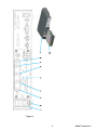
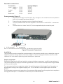
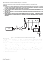
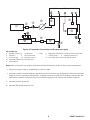
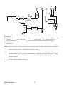
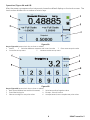
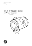
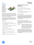
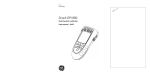
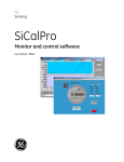
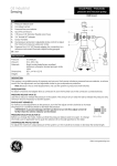
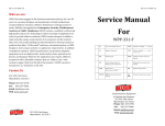
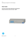
GE Sensing & Inspection Technologies PACE 5000 Pressure Automated Calibration Equipment Safety Instructions and User Guide - K0447 g K0447 Issue No. 2 1 Figure 1 2 K0447 Issue No. 2 Introduction The PACE 5000 Pressure Automated Calibration Equipment measures and controls pneumatic pressure and displays, on a touch-screen, the pressure measurement and controller status. Safety • • • • Do not use this device for any other purpose than that stated. Do not apply pressures above the maximum working pressure stated on the rear panel (Fig 1, item 5). Do not apply electrical power above the maximum values stated on the rear panel (Fig 1, item 2). Refer to the user manual for general pressure equipment requirements. Maximum working pressure (MWP)................................................................................................................ stated on rear panel Pressure media.............................................................................................................................................. clean, dry, nitrogen or air ..................................................................................................................compatible with stainless steel, acrylic, nitrile Pressure connections ............................................................................................................................................... G 1/8 female (filtered) ............................................................................................................................................... 1/8 NPT female optional Key to Figure 1 1 4 8 Fuse and power supply switch on/off -ve supply port 5 Pressure rating Reference port 9 PACE instrument 2 Electrical rating 6 Output port 10 Control module 3 7 +ve supply port Vent port Pneumatic connections WARNINGS: • • • TURN OFF THE SOURCE PRESSURE AND CAREFULLY VENT THE PRESSURE LINES BEFORE DISCONNECTING OR CONNECTING THE PRESSURE LINES. PROCEED WITH CARE. ONLY USE EQUIPMENT WITH THE CORRECT PRESSURE RATING. BEFORE APPLYING PRESSURE, EXAMINE ALL FITTINGS AND EQUIPMENT FOR DAMAGE. REPLACE ALL DAMAGED FITTINGS AND EQUIPMENT. DO NOT USE ANY DAMAGED FITTINGS AND EQUIPMENT. Electrical connections WARNINGS • • THE GROUND LEAD OF THE INSTRUMENT MUST BE CONNECTED TO THE AC SUPPLY PROTECTIVE SAFETY GROUND. ISOLATE THE POWER SUPPLY BEFORE MAKING ANY ELECTRICAL CONNECTIONS TO THE REAR PANEL. Packaging On receipt of the PACE 5000 check the contents of the packaging against the following list: Packaging List - PACE 5000 i) PACE 5000 Pressure Controller. ii) Cable, power supply. iii) User documentation CD (UD-0001). iv) Calibration certificate. v) Diffuser (IO-DIFFUSER-1). vi) Restrictor (IO-SNUBBER-1). Preparation for Use The instrument can be used as a: • Free standing instrument positioned on a horizontal surface. • Rack-mounted in a standard 19 inch rack using the rack-mount accessory option kit (refer to user manual, section 2.5). For free-standing instruments, use the two front feet on the base to elevate the instrument to provide a better viewing angle. Note:The cooling air outlet, positioned under the front of the instrument, must not be obstructed. Allow a free flow of air around the instrument, especially at high ambient temperatures. K0447 Issue No. 2 3 Pneumatic connections Connection Input supply + supply Output Vent Reference G 1/8 G 1/8 G 1/8 G 1/8 G 1/8 optional adaptor 1/8 NPT 1/8 NPT 1/8 NPT 1/8 NPT 1/8 NPT Pressure supply (Figure 2) 1. The pressure supply must be clean, dry, nitrogen or air and at the correct pressure (refer to the supply equipment below). 2. Ensure the user systems can be isolated and vented. 3. Connect pressure and vacuum supplies to the SUPPLY + and SUPPLY - connection ports. 4. Connect the Unit Under Test (UUT) to the required output connection port. 1 G 1/8 connector 2 Bonded seal Note: For instruments with NPT connections, use adequate pressure sealing. Figure 2, Pneumatic Connections Installation The instrument requires a positive pressure supply, instruments operating in an absolute range or negative pressure range require a vacuum supply. A vacuum supply should be used for a fast response for instruments operating near atmospheric pressure. Supply equipment Pneumatic supplies should have isolation valves and, where necessary, conditioning equipment. The positive pressure supply should be regulated at 110% of the full-scale pressure range stated on the control module. On instruments without a negative supply, the positive pressure discharges from the system to atmosphere through the negative supply port. Fit the diffuser to the negative port to diffuse airflow. During system pressure vent operations, the pressure discharges from the system to atmosphere through the vent port. Fit a diffuser to the vent port to diffuse airflow. 4 K0447 Issue No. 2 Pneumatic Connection Examples (Figures 3, 4 and 5) These examples show connection details using supply equipment described above. Caution: • • • • USING THE VENT FUNCTION CAN DAMAGE RATE-SENSITIVE EQUIPMENT CONNECTED TO THIS CONTROLLER. SET THE RATE OF CHANGE FOR THE EQUIPMENT TO A SAFE VALUE. USE THE VENT FUNCTION TO REDUCE PRESSURE AT A CONTROLLED RATE (TASK RATE SETTING) BEFORE THE VENT VALVE OPENS TO ATMOSPHERE. DO NOT EXCEED THE MAXIMUM PRESSURES STATED IN THE APPROPRIATE COMPONENT MAINTENANCE MANUAL FOR THE UNIT UNDER TEST . CAREFULLY DE-PRESSURIZE ALL PIPES TO ATMOSPHERIC PRESSURE BEFORE DISCONNECTING AND CONNECTING TO THE UNIT UNDER TEST . BEFORE TESTING, SET THE RATE OF CHANGE FOR PACE 5000 INSTRUMENTS TO A SAFE VALUE. A HIGH RATE OF CHANGE CAN DAMAGE SENSITIVE COMPONENTS. REFER TO THE APPROPRIATE COMPONENT MAINTENANCE MANUAL FOR THE UNIT UNDER TEST . SUPPLY OUTLET VENT REF 8 a Figure 3, Pneumatic Connections without vacuum supply Key to Figure 3 1 Pressure source 2 Conditioner 3 Filter 4 Regulate to between 110% full-scale and MWP 5 Diffuser * 6 Unit under test 7 Optional reservoir † 8 Optional differential connection a atmosphere Notes:Refer to the PACE User Manual, Reference and Specification for details of other system components. * High pressure gas exhaust - depending on pressure range. † Optimum controller transient response and minimum time to set-point may be degraded if either the pneumatic supply or vacuum system has restricted flow. Installing a reservoir volume, which has larger capacity than the load volume, located in close proximity to the controller supply ports can improve the controller response. Optional differential connection kit. K0447 Issue No. 2 5 SUPPLY OUTLET 11 VENT REF 12 a Figure 4, Pneumatic Connections with vacuum supply Key to Figure 4 1 Pressure source 2 Conditioner 3 5 Diffuser* 6 Unit under test 9 Oil mist trap 10 Vacuum source 12 Optional differential connection a atmosphere Filter 4 Regulate to between 110% full-scale and MWP 7 Check valve ‡ 8 Optional reservoir † 11 Normally open electrical release valve Notes:Refer to the PACE User Manual, Reference and Specification for details of other system components. * High pressure gas exhaust - depending on pressure range. † Optimum controller transient response and minimum time to set-point may be degraded if either the pneumatic supply or vacuum system has restricted flow. Installing a reservoir volume, which has larger capacity than the load volume, located in close proximity to the controller supply ports can improve the controller response. ‡ Optional vacuum system kit. Optional differential connection kit. 6 K0447 Issue No. 2 SUPPLY OUTLET VENT REF 12 a 11 Figure 5, Pneumatic Connections with negative gauge pressure generator Key to Figure 5 1 5 9 11 a Pressure source 2 Conditioner 3 Filter 4 Regulate to between 110% full-scale and MWP Diffuser * 6 Unit under test 7 Check valve ‡ 8 Optional reservoir † Vacuum generator ‡ 10 Source pressure (regulated compressed air supply) Exhaust to atmosphere 12 Optional differential connection atmosphere Notes: Refer to the PACE User Manual, Reference and Specification for details of other system components. * High pressure gas exhaust - depending on pressure range. † Optimum controller transient response and minimum time to set-point may be degraded if either the pneumatic supply or vacuum system has restricted flow. Installing a reservoir volume, which has larger capacity than the load volume, located in close proximity to the controller supply ports can improve the controller response. ‡ Optional negative gauge generator kit. Optional differential connection kit. K0447 Issue No. 2 7 Operation (Figure 6A and 6B) After the power-up sequence the instrument shows the default display on the touch screen. The touch screen divides into a number of mimic keys. Figure 6A Key to Figure 6A (press mimic key to show or select:) 1 Status 2 Switches between measure and control modes 3 Enter new set-point value 4 Controller set-up menu 5 Measure mode set-up menu Figure 6B Key to Figure 6B (press mimic key to show or select:) 1 Back space (deletes last entered character) 2 Switches positive/negative value 3 Enters decimal point 4 Escape - exits this menu 5 Selects new digit for set-point value 6 Accepts (enters) new complete set-point value 8 K0447 Issue No. 2 Maintenance Refer to the User Manual for routine maintenance. Cleaning When necessary, clean externally using a damp lint-free cloth and mild liquid detergent. General Specification Display LCD: Colour display with touch-screen Operating temperature 10°C to 50°C (50° to 122°F) Storage temperature -20°C to 70°C (-4° to 158°F) Ingress protection IP30 (EN60529) Operating humidity 5% to 95% RH (non-condensating) Vibration Def Stan 66-31, 8.4 cat III and MIL-PRF-28800 Type 2 class 5 style E/F EMC EN 61326 Electrical safety EN 61010 Pressure safety Pressure Equipment Directive - class: sound engineering practice (SEP) Symbols The following symbols mark the equipment to identify compliances and hazards. This equipment meets the requirements of all relevant European safety directives. The equipment carries the CE mark. This symbol, on the instrument, indicates that the user should refer to the user manual. This symbol, on the instrument, indicates do not throw-away in domestic bin, hazardous material, dispose correctly in accordance with local regulations. Safe Disposal of Equipment Dispose correctly in accordance with local regulations. Approved Service Agents For the list of service centres visit our web site: www.gesensing.com Trademarks All product names are trademarks of their respective company. © The General Electric Company all rights reserved. K0447 Issue No. 2 9 intentionally left blank 10 K0447 Issue No. 2