1
Rev 1.1
Installation
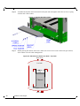
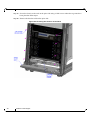
Figure 6: Crate Screws
4. Remove the nylon covers from the chassis.
5. Visually inspect the chassis, make sure that:
• There is no visible damage
• 4 PSUs are installed
6. Remove all protective plastic film from the sides and top of the chassis.
Unpack the system and check against the parts list to make sure that all the parts have
been sent. Check the parts for visible damage that may have occurred during shipping.
If anything is damaged or missing, contact your customer representative immediately.
Do not remove any of the blocks or the lock-down bars at this time.
2.5
Physical Installation
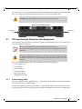
The rack mounting holes conform to the EIA-310 standard for 19-inch racks. Guarantee proper ventilation, by leaving 8cm (3”) of space to the front and rear of the switch.
This ensures proper airflow through the chassis. This is crucial for maintaining good
airflow at ambient temperature. In particular, route cables such that they do not impede
the air into or out of the chassis.
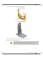
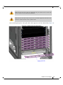
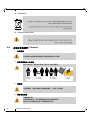
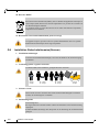
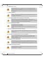
Warning: This equipment is very heavy (257kg; 567lb). Safety is the first concern.
Make sure that adequate manpower and proper equipment is used for transporting and
moving the chassis.
24
Mellanox Technologies