1
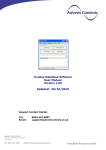
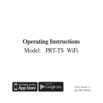
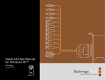
Advent Controls Livekey Host Board
H688V104
Installation Guide
Overview
The purpose of this document is to provide system installers with information about Livekey host
boards, a reference for system installation and a guide to system commissioning. For information
regarding specific readers and database software please refer to our website downloads page at:
http://www.adventcontrols.co.uk/downloads.htm
Contents
1.
2.
3.
4.
5.
6.
7.
Overview……………………………………………………………………………………………………………………. 1
Contents……………………………………………………………………………………………… ……………………. 1
H688V104 Specification……………………………………………………………………… ……………………. 2
Connection to Livekey Compatible Readers…………………………………………………………….. 3
Door Commissioning…………………………………………………………………………………………………. 5
Troubleshooting………………………………………………………………………………………………………… 6
Glossary…………………………………………………………………………………………………………………….. 7
Advent Controls Ltd
St Andrews Business Centre
Liverpool
Tel: 0845 467 0247
Email: [email protected]
1
Practical Access Control
3.
H688V104 Specification
Feature
Min
Max. Users
Doors
Doors per Host
Baud Rate
Protocol
Door Open Time
Supply Current*
Output
Flash-able
Manual Release
Supply Voltage
Switching Capacity DC
Switching Capacity AC
Software Version
Firmware
Data Retention
Nom
1
33600
1
50mA
9
1.05
1
115200
RS232
4
120mA
Relay - NO/NC
Yes
Yes (isolated)
12VDC
1.05
v1.04
10y
Max
Unit
700
70
115200
Users
Doors
Doors
Bit/s
26
200mA
Seconds
milliamps
14
4A (48V)
10A (250V)
Volts DC
Amps
Amps
Years
* Includes Reader
The H688V104 host interfaces with the Livekey ‘C56’ range of readers. It can handle up to 700
users using S50 type key fobs and cards.
The compact unit is designed to be fitted within the power supply housing for the door. It
features a manual exit request input for connection to a ‘safe side’ exit switch. This allows the
unit to form a complete access control solution in one board.
The unit communicates with the reader via a TX/RX pair requiring just 4 connections between the
host and the reader (TX, RX, +V & GND). The device is shipped with a ‘Door Card’ specific to the
individual unit. Any adjustments to the internal settings of the unit are made using the Livekey
software and are applied to the unit using the ‘Door Card’. If the card is lost a replacement PCB
unit is required.
The unit can connect to a fail-safe or fail-open type striker or a magnet lock. Provided, are voltfree Normally Open (NO) and Normally Closed (NC) contacts with a Common (COM) terminal.
The maximum permitted switching loads are stated above.
Advent Controls Ltd
St Andrews Business Centre
Liverpool
Tel: 0845 467 0247
Email: [email protected]
2
Practical Access Control
4.0
Connection to C56 Range Readers
The reader positive supply and GND connection must be made to the host board. This is because
the host controls the supply voltage to the reader. The reader supply should never be
connected directly to the power supply outlet terminals.
Terminal
Terminal
Terminal
Terminal
Terminal
Terminal
Terminal
Terminal
Terminal
Terminal
Terminal
Terminal
1 – Output COM
2 – Output NC
3 – Output NO
4 – GND (to PSU)
5 – Supply Input (to PSU)
6 – Exit Sw. Supply
7 – Exit Sw. Input
8 – Reader Supply (+VE)
9 – Reader Supply (GND)
10 – Cable Screen COM (GND)
11 – RXD (to Reader TXD)
12 – TXD (to Reader RXD)
Fig. 1 H688V104 Pin-out
PSU
EXIT
Fig. 2 Typical Connection Diagram
Advent Controls Ltd
St Andrews Business Centre
Liverpool
Tel: 0845 467 0247
Email: [email protected]
3
Practical Access Control
4.1
Readers with Cable Connector
Livekey readers are available with a pigtail connection or a screw terminal block connector.
Where a pigtail connection is specified it is likely that the cable will require an extension to reach
the host board (typically mounted in the power supply housing). Only four wires within the cable
require extending and these are the Red (12V), Black (GND), Green (RXD) and White (TXD).
Due to the high speed data connection between the host and reader the cable should be kept as
short and straight as is possible. If the total cable length exceeds 5m then the baud rate of the
reader must be reduced. This is done using the PC software and, in order to ensure effective
reader-host communication, the reader must be temporarily connected directly to the host.
Please see Commissioning for more information.
The cable length should never exceed 15m.
4.2
Readers with Terminal Block Connector
When using a reader with a terminal block connector it should be noted that the data lines are
directional and are labelled with respect to the actual device. Therefore as the host transmits
data to be received by the reader the host TX connection should be connected to the reader RX
connection and vice-versa.
As with the pigtail device only the power supply and data connections are required hence 4-core
cable is sufficient.
Care must be taken regarding polarity when connecting the reader to the host. If the
power supply cable is reversed damage to the reader will result!
Advent Controls Ltd
St Andrews Business Centre
Liverpool
Tel: 0845 467 0247
Email: [email protected]
4
Practical Access Control
5.0
Door Commissioning
Adding a door reader and host to the site is very simple process. Each host PCB is supplied with its
own Door Enrolment Card (DEC) which is used to communicate setup information with the PC.
To enrol the door onto the system place the DEC on the PC programmer. By simply clicking the
‘Query Card’ button the software will automatically recognise that the DEC is present and open the
door setup form.
Fig. 3: Door Setup Screen
The door should be named and a description can also be added. The Door Number is automatically
assigned by the software and cannot be amended.
The door open time (for both manual release and key fob release) should be specified on this form
and defaults to 4s.
If a door is enrolled after the user cards have been enrolled and distributed the group of users who
require access to the door should be specified in the ‘Add User Group’ box. For details on creating a
user group please refer to the Livekey Database Software User Manual. Please note that the User
Group feature can be used at any time should the manager require a change off access conditions
for a group of users on a door.
Once the form is complete the ‘OK’ button should be clicked and the operator should wait for the
card write confirmation to be shown. The card should now be presented to the door reader to
complete the commissioning process (i.e. to transfer the site and setup data from the PC to the
reader).
5.1
Changing the Baud Rate
The Door Setup form allows for selecting one of three baud rates. For longer cable runs or
operation in a noisy environment a lower baud rate should be selected. A lower baud rate should
be avoided where possible as it will slow card processing operations unnecessarily (this may
become noticeable when there are a lot of users on the system).
When using a setting other than ‘High’ the reader should be connected directly to the host when
communicating with the DEC.
Advent Controls Ltd
St Andrews Business Centre
Liverpool
Tel: 0845 467 0247
Email: [email protected]
5
Practical Access Control
6.0
Troubleshooting
Symptom
Problem
Resolution
The reader repeatedly switches
off and on
If the host fails to
communicate effectively with
the reader it will cycle the
power to reset the reader
The data (RXD/TXD) terminals
are reversed
The data cable is too long
Ensure a good connection has
been established between the
host data terminals and the
reader
Ensure the data lines are
connected correctly
Ensure the cable does not
exceed 15m
Re-route cable away from
source of noise
The data cable is too close to
sources of electrical noise such
as mains cable
The baud rate to too high. If
the cable is longer than a few
meters the baud rate must be
reduced
The reader does not appear to
communicate with the DEC,
however, the reader remains on
and does not cycle
The reader does not recognise
user cards
An active card cannot open the
door
I have lost my Door Enrolment
Card (DEC)
This is likely to be caused by
electrical interference on the
data lines
The system must be enrolled
on the PC using the DEC before
it will recognise a user card
If the door has been enrolled
after the card was programmed
the card will not have been
permitted access to the door
This card cannot be replaced
and a new host is required
Advent Controls Ltd
St Andrews Business Centre
Liverpool
Tel: 0845 467 0247
Email: [email protected]
Connect the reader directly to
the host. If the problem
persists use the PC software
and Door Enrolment Card
(DEC) to reduce the baud rate
This can be tested for by
removing the reader and
connecting it directly to the
host as described above.
Enrol the system using the PC
software
Either re-program the
individual user card with access
to the door or add the user to a
User Group and use the DEC to
enrol this group of users.
Please see section 5. Door
Commissioning for more
information
Please contact
[email protected]
for assistance
6
Practical Access Control
7.0
Glossary
DEC
Pigtail Connection
Host
Door Enrolment Card – The card used for PC communication with an individual
door
The reader has a cable soldered directly to the circuit board and connection is
made using this cable
Refers to the PCB external to the reader mounted in a ‘safe’ or secure area of
the building.
Advent Controls Ltd
St Andrews Business Centre
Liverpool
Tel: 0845 467 0247
Email: [email protected]
7
Practical Access Control