1
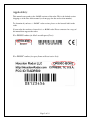
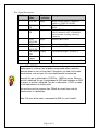
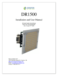
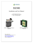
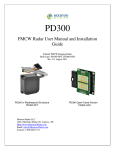
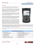
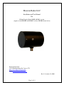
Houston Radar LLC Installation and User Manual For K-Band Doppler Radar DR500 (-BOM2) version (Applies to both DR500S and DR500C versions, DR500S shown below) Houston Radar LLC 13814 Sherburn Manor Dr. Cypress .TX Http://www.Houston-Radar.com Email: [email protected] Rev 11, October 13th 2009 Page 1 of 19 This device complies with part 15 of the FCC Rules. Operation is subject to the following two conditions: (1) this device may not cause harmful interference, and (2) this device must accept any interference received, including interference that may cause undesired operation. This device conforms to the CE mark and conforms to the requirements of the applicable European Directives as follows: EN 60950-1 ETSI EN 300 440-1 V1.4.1 ETSI EN 300 440-2 V1.2.1 ETSI EN 301 489-1 V1.7.1 EN 55022 Class B EN 61000-4-2 8 kV/4 kV EN 61000-4-3 3 V/m The DR500C open frame radar is sensitive to electrostatic discharge. Please observe handling precautions. Note: Specifications may change without notice. Note: Not liable for typographical errors or omissions. Page 2 of 19 Applicability: This manual corresponds to the –BOM2 versions of the radar. This is the default version shipping as of the date of this manual (see front page for date and revision number). To determine if you have a “–BOM2” radar version, please see the barcode label on the radar. If your radar does not have a barcode it is a –BOM1 radar. Please contact us for a copy of the manual that supports that radar. For DR500S radars (in black weatherproof box): For DR500C radars (in open frame without outer box): Page 3 of 19 Table Of Contents APPLICABILITY: ........................................................................................................... 3 INTRODUCTION............................................................................................................. 5 INSTALLATION.............................................................................................................. 6 MOUNTING: ..................................................................................................................... 6 DIRECTION POINTING:...................................................................................................... 6 HOOKUP:.......................................................................................................................... 7 Power Input: ............................................................................................................... 7 Serial Connection: ...................................................................................................... 7 Setting Detection Sensitivity via the ASCII Interface: ................................................ 7 Log/Statistics Storage: ................................................................................................ 8 USE................................................................................................................................... 10 COLLECTING AND ANALYZING IN-RADAR TRAFFIC STATISTICS............ 10 REAL TIME TRAFFIC STATISTICS IN THE RADAR:......................................... 10 CONFIGURING THE RADAR .................................................................................... 11 SETTING CONFIGURATION VARIABLES IN THE RADAR:.................................................. 12 OPTIONAL INFRARED REMOTE PROGRAMMING: ............................................................ 13 Speed Low Limit: ...................................................................................................... 14 Speed High Limit: ..................................................................................................... 14 Speed Limit: .............................................................................................................. 14 Detection Sensitivity: ................................................................................................ 15 Internal Clock: .......................................................................................................... 15 Self Test:.................................................................................................................... 16 Display Units (MPH or KMPH):.............................................................................. 16 Reset Factor Settings: ............................................................................................... 16 Set Serial Baud Rate: ................................................................................................ 17 DR500 SPECIFICATIONS............................................................................................ 18 GENERAL ....................................................................................................................... 18 APPROVALS ................................................................................................................... 18 DATA INTERFACES ......................................................................................................... 18 MECHANICAL ................................................................................................................. 18 PERFORMANCE ............................................................................................................... 19 ADVANCED STATISTICS ................................................................................................. 19 Page 4 of 19 INTRODUCTION Congratulations on your purchase of the Houston Radar LLC’s directional Doppler speed radar DR500 (available in weatherproof DR500S or open frame DR500C options). This state of the art K-band microwave Doppler speed radar is specifically designed for the license free, battery operated speed radar market, for use in speed awareness trailers, school zones and other speed restricted traffic zone speed awareness uses. Utilizing the latest in high performance, ultra low power DSP (Digital Signal Processing) technology, you will find that this high quality product meets your exacting standards for performance and reliability. Some of the highlights of this product include: FCC approved and with CE mark‡ for your convenience and piece of mind Advanced DSP based performance yields consistent performance and speed detection 1500+ feet (450+ m) of pickup distance for incoming vehicles on open and level road Standard serial port hookup and data format allows hassle free use in existing systems o Use in place of existing products o Interface to your message displays o Use in your speed trailers o Use in school zones 2nd True serial port option available. Now connect to different devices simultaneously Only 0.7 W power usage is up to 4X lower vs. competing solutions and allows use of smaller batteries and solar panels- saving you money Rugged weatherproof enclosure features side mounts and short depth (DR500S only) Built in clock/calendar keeps time even with DC power removed Only 1 mA power consumption in standby mode Radar internal software is “bootloader” flash upgradeable in the field Optional infrared remote control allows you to change/set radar parameters including: o Min/Max speed limit of detection o Speed limit setting for flashing display digits o Sensitivity setting for changing detection range o Internal clock/calendar o Serial port settings o Radar built in self test Now Featuring Optional Integrated “Advanced In-Radar” Traffic Statistics Package with: o Multi-vehicle/multi-lane tracking allows better accuracy over competing units o 2 months of speed as well as count statistics saved in internal memory o Real time clock keeps stats with date/time o Unmatched Windows based “Stats Analyzer” software to download, manage, analyze and plot your stats information from all your DR-500S radars available as option o Stats saved in mph or kph units per display option ‡CE Mark on DR500S only Page 5 of 19 INSTALLATION Mounting: The DR500S is supplied in a weatherproof enclosure and may be conveniently mounted via the side-mounting bosses, outside the speed trailer enclosure to facilitate pointing it into the oncoming traffic. Two #10-24 size screws are required for side boss mounting (provided). Care must be taken to ensure that the provided “split washer” is used to ensure the mounting screw remains tight under vibration. The DR500C is provided in an open frame format with 4x M2.5 standoffs on the top of the PCB for mounting. Please request an outline drawing from Houston Radar for mounting details. If a battery is installed in the radar, you must ensure that this Lithium backup battery does not short to the frame or battery ground. Direction Pointing: The DR-500 is directional in nature. It rejects traffic moving away from it and only measures oncoming traffic. If the optional stats analyzer feature is purchased with the unit, stats will only be collected for incoming traffic. This allows you to position the unit in a median without worry of picking up traffic on the outgoing lane For optimal performance: Radar should be mounted with the mounting bosses horizontal to the road. Radar should be pointed into the direction of the oncoming traffic. Radar should be placed along the size of the road to minimize the angle of the oncoming traffic to the radar. o If radar cannot be placed right along the side of the road, it should be pointed at least 200-300 feet up the road into oncoming traffic. The radar may pickup rotating fans. Avoid pointing it at fans or compressors. Radar should be mounted at least 3 feet high from the road for optimal performance and at least 5 feet off the ground for pickup distance of 1500+ feet. Page 6 of 19 Hookup: Power Input: The DR500 radar should be powered from a nominal 12V DC battery and features industry leading nominal operational power consumption of less than 60mA. This is up to 5X lower than competing products. This operational power translates directly into a longer battery life or gives you an option to power the unit from smaller batteries that would also require smaller solar panels. Serial Connection: The DR500 has a standard 3 wire (RX, TX and Ground) RS232 port to output speeds and accept configuration settings. Speed data is output serially in mph (or Kph if set via the remote) as three ASCII digits in the following format: nnn\r\n where: nnn : The three digit ASCIII speed digits in mph/kph \r\n : A new line followed by a carriage return character When no further vehicles are detected, the radar outputs: 000\r\n or ?000\r\n (once or repeating depending on configuration) This format is compatible with other industry formats including a standard RS232 serial port on a PC, message boards and speed displays. Note: Optionally, the radar may be set to output the display speed in +nnn\r format. Please see serial port config settings table later section. Setting Detection Sensitivity via the ASCII Interface: In addition through the optional IR interface, the radar also allows programmatic sensitivity setting (and many other parameters in an industry compatible manner- contact us for details). Over the serial interface, send in ASCII the following commands: Sensitivity:nn\n and Sensitivity?\n Page 7 of 19 In the 1st case it sets the detection sensitivity to "nn" where nn is from 10 to 99 and is a % of the max detection distance (typically about 1500 feet but can vary with installation effects and size of the target). If the sensitivity is set ok, it replies with OK\n Log/Statistics Storage: The DR500 radar has capacity to store traffic statistics in user programmable time bin intervals (default is 5 minute bins which yields 60 days of storage) and features a clock/calendar that retains time even when external power is removed. The clock is used to time stamp the collected statistics. Stats are stored in mph or kph units. This depends on the display units of the stats. See the IR remote programming section to change the display units of the radar. This feature is an add-on software option. Please contact Houston Radar LLC for purchase of this option. Detecting traffic statistics inside the radar has tremendous advantages: Radar tracks multiple vehicles at different speeds simultaneously and hence does not miss vehicles visible to it Radar access to all return signal parameters of the target vehicles processed by proprietary software inside radar makes full use of every bit of information present in reflected signal and dramatically improves counting accuracy No add-on boards keeps total system power usage down and reliability up Advanced Statistics are software “key enabled” allowing turn-on in the field or after the radars have shipped to the sign manufacturer Easy Bluetooth wireless access using standard Bluetooth modules you buy from your source. Now enable statistics collection wirelessly! Please see a white paper on this topic on our web site for further discussion on this topic including some actual field test results. You may download it from the following URL: http://houston-radar.com/downloads/HoustonRadarAdvancedStatisticsWhitePaper.pdf Page 8 of 19 Wire Signal Descriptions: DB9 Pin # 1 2 3 4 5 6 7 8 9 Signal Name +12V DC Direction Description (wrt Radar) Input PRI RS 232 TX PRI RS 232 RX Output AUX RS232 RX GND AUX RS232 TX Panel Power Save Do not connect GND Input Radar + Power Supply. Connect to battery + 9.5VDC to +18VDC Primary RS232 transmit output from Radar Primary RS232 receive input. Required only if connected to PC to download stats from unit or setting sensitivity parameter Auxiliary RS232 RX Input Output System Ground. Connect to battery Auxiliary RS232 TX Output “Open Drain Output”. See Note 1. N/A Do not connect. Input System Ground. Connected to wire #5. Input Note 1: The DR500 features an output that can wake up an external display panel(s) to bring it out of power saving mode when a vehicle is detected above a user set threshold. If the panels you hook to the radar do not feature such an input, this wire should remain unconnected. Normally this pin is pulled up to +12VDC by ~18KOhm resistor. When a vehicle is detected, this pin is pulled down to GND and held down to GND as long as a vehicle is detected. This pin is released to +12VDC as soon as the radar detects no further traffic. You must ensure that no more than 150mA of current flows into this terminal when it is pulled low. Note: The case of the radar is connected to GND (i.e. pin 5 and 9). Page 9 of 19 USE Turn on the power to the DR500 to make it operational. No other action is required. The radar will output data over the serial port(s) whenever it detects a vehicle that is above the programmed lower speed limit and below the programmed high limit. The default limits are set at 5mph (kph) and 99mph (kph) at the factory (but may be different for a particular user. Please consult the factory test report that is included with the radar). Using the optional IR remote control or the serial interface, program the high limit to blank out the speed display above this limit. This will prevent “racing against the radar” by denying a speed feedback display of excessive speeds as determined by you. On initial power up or upon being taken out of standby (by the RED stdby button on the IR remote), the radar counts up from 000 to 010 to provide a quite visual check that it is operational. If you use the RED Stdby button on the IR remote control to put the radar in standby mode, it counts down from 010 to 000 to provide a quick visual check that it powered down. Collecting and Analyzing In-Radar Traffic Statistics The DR500 Radar supports optional “In-Radar” advanced traffic statistics collection. This feature is sold separately. If you radar has this feature enabled you may collect the stored statistics by using the provided Houston Radar Advanced Statistics Analyzer Windows program. This program must be installed on a MS Windows 2000, XP or Vista PC and allows the retrieval of stored statistics from the radar by using a PC serial port. It also has features to generate traffic reports, plot interactive graphs and export the raw data to a MS Excel file. Please refer to the on line help functionality of the program after you install it on your computer for detailed instructions on how to use its functionality. Real Time Traffic Statistics In the Radar: The DR500 In-Radar stats software now features “real time” histogram statistics. These are updated as soon as a vehicle is detected and may be read out as a speed bin count “histogram”. Thus no historical records need be read out and parsed to read statistics. This feature requires a host program to be on-line to read the live statistics. Please contact Houston Radar for more information if you are interested in acquiring live statistics from the radar. Page 10 of 19 CONFIGURING THE RADAR The DR500 radar is configured by setting the following internal parameters: The unit’s internal parameters are configured by connecting the radar’s RS232 port to a PC’s RS232 serial port and using the Houston Radar Advanced Stats Analyzer program’s configuration screen as described here. The following internal “variables” may be set. Their functions are described below: Radar Description Configuration Variable Name Sets the primary RS232 serial port’s baud rate and output format. Do RS not change this value unless a value is provided by Houston Radar. Sets the auxiliary RS232 serial port’s baud rate. RA Sets the internal speed units of the radar. All LO, SP & HI speeds are UN interpreted to be in this units. 0 = MPH 1 = KPH Low speed cutoff. Vehicle speeds are not output below this speed. LO Minimum value is 2. Should be set to be less than HI. High speed cutoff. Vehicles speeds are not output above this speed. HI Maximum value is 159. Should be set higher than LO speed. Flashing speed limit. Any speed higher than this value flashes the SP trigger output at 2/3 duty cycle, 1Hz. Sending out 000 between nnn speed values also interrupts the speed output to signal “flashing”. Target detection sensitivity. Valid values are from 10 to 99 and are a ST percentage of max range. So a value of 50 would yield about 750 feet detection. Note: This is not range setting but detection sensitivity. Thus if large vehicles are being detected at 2000 feet, a value of 50 will make them detect at approx 1000 feet etc. 1 = Select Fastest Target for speed output SF 0 = Select Strongest Target for speed output Set from 1 to 60 minutes of binning interval for stats collection. BN Traffic data binned (see below) and is accumulated for this duration in the bins and then a time stamped record made in stats memory in the radar. Speed bins are factory set and cannot be changed. They are: 5 MPH bins for MPH units (20 bins in total from 0 to 105 MPH) 10 KPH bins for KPH units (17 in total from 0 to 170 KPH) Radar mode bits mask. The bits controls speed output on primary and MO aux serial ports, rapid output update and other functionality. (bit 0 -> 0 = SI3 compatibility mode for ASCII commands) (bit 1 -> 1 = Enable ASCII output on primary serial port) (bit 2 -> 1 = Enable ASCII output on auxiliary serial port) Reserved. Do not set unless value provided by Houston Radar KY Page 11 of 19 Setting Configuration Variables in the Radar: 1. Install the provide Houston Radar Advanced Stats Analyzer Windows program on a Windows 2000, XP or Vista computer. 2. Connect the radar RS232 port to the PC’s RS232 serial port. If the PC does not have a serial port you may buy a USB serial converter dongle (from BestBuy, Radioshack or any Internet store). 3. Power up the radar. 4. Start the Houston Radar Stats Analyzer program on the computer (Start->All Programs->Houston Radar->Houston Radar Stats Analyzer) 5. In the program window, click on Start->Connect to Radar… 6. Click on “Connect” button. 7. Ensure you see a “Radar found on COM” message. The COM # will depend on your computer . 8. Click on OK. Now you are ready to configure the radar. 9. To configure the LO, SP & HI limits, click on “Radar Limits” menu bar item. The three fields show the current values of the three variables. Change the variables to the desired values and click on “Save”. 10. To configure any other variable, click on “Advanced->Radar Configuration”. In the window that comes up, enter the two letter variable name in the “Variable” field (from the table on previous page). Enter its value in the “Value” field and click on “Set Variable” button. Page 12 of 19 Optional Infrared Remote Programming: You may order the DR500 radar with an optional IR receiver port. By default the DR500-BOM2 radars do not have the IR receiver installed. All –BOM1 radars had the IR receiver installed. The DR500S operational parameters may be accessed and programmed in the field using an optional infrared remote control. These features may only be programmed in conjunction with speed display panels that support visual feedback of ASCII chars sent on the serial data line. Contact the factory for availability and a list of panels that support this feature. However, the Houston Radar LED panels do support this feature. THE IR REMOTE CONTROL IS NOT REQUIRED FOR BASIC SPEED DETECTION AND OPERATION OF THE RADAR. Optional DR500 Remote Control (radar must be ordered with the IR port option) Page 13 of 19 This section describes these features and how to program the values into the radar using the IR remote. Apply +12 V DC battery power to the radar power wires. Stand in front of the radar, between 2 and 10 feet away and point the IR remote at the front face of the radar (the IR receiver window is the small circular hole below the rectangular window). Then execute the following steps to program the desired functions: Speed Low Limit: Use this feature to only give speed awareness feedback to vehicles over a certain limit, for example the road speed limit. This would setup the system to not display the speeds of vehicles that are below the limit, rather only display the speed of vehicles that are above the limit. With panels that support the “power saving mode”, this can result in very significant power savings and significantly extend operation time between battery recharges. 1. Press the “LOW LIMIT” key once [The current value will be displayed on the display] 2. Enter the numeric speed for the low limit (or use the Up/Down arrow keys) 3. Press “SET/OK” to save the limit in the radar or press “CANCEL” at any time before “SET/OK” to cancel this operation Speed High Limit: Use this feature to blank out the speed display of vehicles over this limit. You can use this feature to defeat “racing against the radar” issue. 1. Press the “HIGH LIMIT” key once [The current value will be displayed on the display] 2. Enter the numeric speed for the high limit (or use the Up/Down arrow keys) 3. Press “SET/OK” to save the limit in the radar or press “CANCEL” at any time before “SET/OK” to cancel this operation Speed Limit: Use this feature to flash the speed display of vehicles over this limit. You can use this feature to draw attention to the speed of vehicles going over the set limit. 1. Press the “SPEED LIMIT” key once [The current value will be displayed on the display] 2. Enter the numeric speed for the speed limit in effect at the current location 3. Press “SET/OK” to save the limit in the radar or press “CANCEL” at any time before “SET/OK” to cancel this operation Page 14 of 19 Detection Sensitivity: Use this feature to set the detection sensitivity. This affect the distance the radar detects objects. You may set the sensitivity from a value of “10” to “99”. Each value is an approximate percentage of maximum detectable range (typically 500 to 600 feet for the DR-500S). Setting the value to “99” sets the range to maximum. This is due to typically only two display digits being used with the radar. 1. Press the “SENSITIVITY” key on the remote once [The current value will be displayed on the display] 2. Enter the desired sensitivity as a two digit value from 10 to 99 percentage of maximum range of the radar or use the Up/Down arrow keys 3. Press “SET/OK” to save the limit in the radar or press “CANCEL” at any time before “SET/OK” to cancel this operation Note: Sensitivity may also be set programmatically via the serial interface by sending the radar ASCII commands. Please see the section titled ‘Setting Detection Sensitivity via the ASCII Interface’ for details. Internal Clock: Use this feature to set the internal clock of the radar. This is only required if you have purchased the optional statistics collection package. The unit will keep time even with external power removed. It may be more convenient to set the clock of the radar by connecting a serial cable to the radar and using the “Houston Radar Stats Analyzer” program. A button in the program allows you to sync the radar clock with your computer clock. However, the following steps may be used in the field to either check or set the time of the radar 1. Press the “CLOCK” key on the remote [The radar will display “SE”- short for seconds of the current time] 2. Press the “UP” arrow key on the display to move to the minutes option [The radar will display “MI”- short for minutes of the current time] 3. Press the “UP” arrow key on the display to move to the hours options [The radar will display “HO”- short for hours of the current time] 4. Press the “UP” arrow key on the display to move to the day of the month option [The radar will display “DA”- short for day of the current day of the month] 5. Press the “UP” arrow key on the display to move to the month option [The radar will display “MO”- short for month of the current date (January is “1”, December is “12”)] 6. Press the “UP” arrow key on the display to move to the month option [The radar will display “YE”- short for year of the current date (2000 is “00”, 2006 is “06” etc.)] Page 15 of 19 To set any of the above value, navigate to the desired option, then press “SET/OK”. At this point the radar will display the current option. You may then directly enter the desired value for the option and press “SET/OK” again. Press “CANCEL” to at any time or after the final “SET/OK” to exit the menu. Self Test: Press the “SELF TEST” key on the remote to instruct the radar to perform a self test. The radar will display “OK” after about 6 seconds if the test passes. It will then reset and count up from 1 to 9 and then the display will blank out. If the test fails, it will display a numeric digit indicating the numbers of internal tests that failed. If you can connect the radar to a computer using a “terminal” program, you may conduct a more detailed self-test. Contact Houston Radar for details. Display Units (MPH or KMPH): 1. Press the “F1” key on the remote [The radar will display “F1”] 2. Press the “4” key [The radar will display the current value code. 0 = MPH, 1 = KPH] 3. Press 0 to display speed in MPH or 1 to display speed in KPH 4. Press “SET/OK” key to save in memory. [Radar will restart and count up from 1 to 9 and the display will go blank. The unit is now ready. Note. The limit values are applied as-is. Thus the default high limit value of 99 is 99 mph in mph mode and 99 kph in kph mode.] Reset Factor Settings: 1. Press the “F1” key on the remote [The radar will display “F1”] 2. Press the “3” key on the remote 3. Press the “SET/OK” [Radar will display “OK” and then restart and count up from 1 to 10 and the display will go blank. This will reset the baud rate to 115200, display units to MPH, low limit to 5mph, high limit to 99mph and speed limit to 99mph]. Page 16 of 19 Set Serial Baud Rate: This configuration is only required at the factory when mating the radar to the selected speed digit display panels. Once configured, the radar keeps the configuration even after power is removed and need not be reconfigured. The optional statistics package can communicate with the radar to download saved statistics at any set radar baud rate. The baud rate of the radar is automatically detected by the stats package (Autobaud capability). Use this feature to set the baud rate of the serial data port by following the following steps: Select the baud rate from the table below and note the key combination from the “Key #” column in the table. Press the “Set Baud “ key on the IR remote followed by the two digit numeric code from the desired baud rate row picked in #3 above, followed by the “Set/OK” key. You may press cancel any time in the above procedure to cancel programming the new baud rate. The new baud rate is not stored and changed till you press the “Set/OK” key. Your baud rate is now programmed in permanent memory and if you have speed display panels hooked up, they will display the two digit key combination that you entered to select the baud rate. If you want to change the baud rate of the radar, you can simply follow the above procedure and select a new baud rate any number of times. Even Odd None None ASCII Output Format nnn\r\n nnn\r\n nnn\r\n nnn\r\n SET SET SET SET BAUD BAUD BAUD BAUD + + + + 10 11 12 13 1 1 1 1 Even Odd None None nnn\r\n nnn\r\n nnn\r\n nnn\r\n SET SET SET SET BAUD BAUD BAUD BAUD + + + + 20 21 22 23 1 1 1 1 1 Even Odd None None None nnn\r\n nnn\r\n nnn\r\n nnn\r\n +nnn\r SET SET SET SET SET BAUD BAUD BAUD BAUD BAUD + + + + + 30 31 32 33 34 Baud Rate (bps) 1200 1200 1200 1200 # Data Bits 7 7 7 8 # Stop Bits 1 1 1 1 Parity 2400 2400 2400 2400 7 7 7 8 9600 9600 9600 9600 9600 7 7 7 8 8 Key # 115,200 8 1 None nnn\r\n SET BAUD + 43 115,200 8 1 None +nnn\r SET BAUD + 44 Note: The radar has numerous other baud rates and output format options that can be set via the serial port. Contact Houston Radar if one of the above is not suitable for your requirements. Page 17 of 19 DR500 SPECIFICATIONS General Operating Band Frequency Power Output Antenna Gain Polarization Supply Voltage Reverse Battery Detection Range K-Band 24.125 GHz ±25Mhz 5mW 21 dB Linear 9V DC to 18V DC Protected Typically 1500+ feet on open & level road w/ radar mounted 5 feet above road. (at least 1000 feet with radar 3 feet above road). Nominal Current Draw approx 58 mA (+/-4ma,) (@+12V DC) Operating Temp. -22°F to +185°F (-30°C to +85°C) Weatherproof Yes (IP65) (only DR500S package option) IR Remote Programmable Yes (optional) Approvals Approvals CE (DR500S only) FCC Part 15 European R&TTE directive (1999/5/EC) EN 60950-1 ETSI EN 300 440-1 V1.4.1 ETSI EN 300 440-2 V1.2.1 ETSI EN 301 489-1 V1.7.1 EN 55022 Class B EN 61000-4-2 8 kV/4 kV EN 61000-4-3 3 V/m Data Interfaces Serial Communication Data Rate Data Format Data & Pwr Connector 2x RS232 with independently programmable baud rates Baud Rates from 1200 to 115200 baud Selectable via IR Remote or serial port or factory set. (Please refer to user manual or contact Houston Radar) DB9 Male (DR500S) wired as DCE, DB9 Male on DR500C Note: Not all pins are RS232 signal compatible. Mechanical Weight Length Cable Exit Mounting Width approx 1.2lb/0.5Kg (DR500S enclosure option). 5.5 inches Bottom (DR500S) Two side bosses using 2X #10-24 screws (provided) (DR500S) 3.7 inches dia body (DR500S) 4” inches @mounting bosses (DR500S) Page 18 of 19 Performance Accuracy Speed Range Detection Range ±0.1 mph internal rounded to 1mph external output over ASCII 2 mph to 105 mph (5 to 105mph recommended) (3 Kmph to 168 Kmph) Typically 1500+ feet detecting compact car, further with larger vehicles. Can vary with installation & road conditions and target radar cross section. Advanced Statistics Storage Last 60 days in 5 min bins & 20 (5 mph) speed bins mph mode Last 60 days in 5 minute bins & 17 (10 kph) bins in kph mode Multi-vehicle capable Yes (in multiple lanes for approaching traffic) Internal Clock Battery Life At least 3+ years on the shelf with radar un-powered. 5+ years under normal radar operation in the field. Note: Advanced Statistics is sold as an option in the radar. Page 19 of 19