1
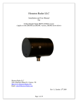
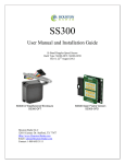
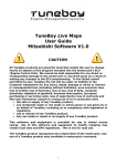
DR1500
Installation and User Manual
K-Band Doppler Speed Radar
Built Type: DR1500-BOM2
Rev 2, April 15th 2009
Houston Radar LLC
13814 Sherburn Manor Dr. Cypress .TX
Http://www.Houston-Radar.com
Email: [email protected]
Contact: 1-888-602-3111
Houston Radar DR1500 User Manual
This device complies with part 15 of the FCC Rules. Operation is subject to the following
two conditions: (1) this device may not cause harmful interference, and (2) this device
must accept any interference received, including interference that may cause undesired
operation.
Changes or modifications not expressly approved by the party responsible for compliance
could void the user's authority to operate the equipment.
Any modification or use other than specified in this manual will strictly void the
certification to operate the device.
This device carries FCC modular approval and as such is labeled with FCC ID
TIADR1500. If this label is not visible when the module is installed inside another
device, then the outside of the device into which the module is installed must also display
a label referring to the enclosed DR1500 module. This exterior label can use wording
such as the following: “Contains Transmitter Module FCC ID: TIADR1500” or
“Contains FCC ID: TIADR1500.” Any similar wording that expresses the same meaning
may be used.
Page 2 of 19
Houston Radar DR1500 User Manual
Warning: DR1500 radar is supplied in an open frame format with exposed antenna and
electronics and thus is a static sensitive device. Please use static precautions when
handling. Warranty does not cover damage caused by inadequate ESD procedures and
practices.
Note: Specifications may change without notice.
Note: Not liable for typographical errors or omissions.
Page 3 of 19
Houston Radar DR1500 User Manual
Table Of Contents
INTRODUCTION............................................................................................................. 5
INSTALLATION.............................................................................................................. 5
MOUNTING: ..................................................................................................................... 5
DIRECTION POINTING:...................................................................................................... 6
RECOMMENDED ENCLOSURE FOR THE DR1500:.............................................................. 6
HOOKUP:.......................................................................................................................... 7
Power Input: ............................................................................................................... 7
Serial Connection: ...................................................................................................... 7
Measured Speed Output:............................................................................................. 7
Setting Detection Sensitivity via the ASCII Interface: ................................................ 7
Log/Statistics Storage: ................................................................................................ 9
HTTP://HOUSTONRADAR.COM/DOWNLOADS/HOUSTONRADARADVANCEDSTATISTICSWHITEPAPER.PDFWI
RE SIGNAL DESCRIPTIONS:............................................................................................... 9
WIRE SIGNAL DESCRIPTIONS: ........................................................................................ 10
USE................................................................................................................................... 11
COLLECTING AND ANALYZING IN-RADAR TRAFFIC STATISTICS............ 11
REAL TIME TRAFFIC STATISTICS IN THE RADAR:......................................... 11
Internal Clock: .......................................................................................................... 13
Configuring the Unit:................................................................................................ 13
Setting Variables in the Radar:................................................................................. 15
DR1500 SPECIFICATIONS.......................................................................................... 17
GENERAL ....................................................................................................................... 17
APPROVALS ................................................................................................................... 17
DATA INTERFACES ......................................................................................................... 17
MECHANICAL ................................................................................................................. 17
PERFORMANCE ............................................................................................................... 18
APPENDIX A: HOOKING UP TO THE TRIGGER OUTPUT ON THE RADAR 19
Page 4 of 19
Houston Radar DR1500 User Manual
INTRODUCTION
Congratulations on your purchase of the Houston Radar directional Doppler Speed Radar
DR1500. This state of the art 24GHz K-band microwave Doppler radar is specifically
designed for the license free battery operated speed measurement and monitoring market.
Utilizing high performance, ultra low power DSP (Digital Signal Processing) technology
and microwave components based on a planar patch array antenna with integrated low
power PHEMT oscillator, you will find that this high quality product meets your exacting
standards for performance and reliability.
Some of the highlights of this product include:
Best in class low power usage of only 32 mA at 12VDC (0.38 Watt)
Small and thin size to allow easy incorporation into your enclosure
Advanced DSP based algorithm yields consistent performance and speed
detection
Typically up to 366 m (up to 1200 feet) of pickup distance for incoming vehicles
on open and level road
Two independent RS232 serial ports enhances connection flexibility
One trigger output is capable of sinking 600 mA and is activated upon vehicle
detection
Radar internal software is upgradeable in the field via RS232 PC interface.
Optional In-Radar advanced traffic statistics capability available
All radar configuration parameters can be set by user via RS232 serial port.
Extensive built-in self test.
INSTALLATION
Mounting:
DR1500 is supplied in an “open frame” format. It requires a weatherproof enclosure
before it may be used outdoors. Alternatively it may be mounted as a component in
another product that already has a weatherproof enclosure.
The DR1500 should be mounted such that the DB9 connector points left or right as
shown in the picture on the front page. This results in maximum pickup range.
The unit may be rotated 90degrees from the suggested optimal mounting. However, in
this case, the detection range may be reduced by about 25%.
Page 5 of 19
Houston Radar DR1500 User Manual
Direction Pointing:
The DR1500 is directional in nature. It only detects traffic in the incoming
direction and rejects all traffic moving in the outgoing direction.
If you wish to detect outgoing traffic, please contact us for more information.
For optimal performance:
Radar should be mounted as suggested in the section titled “Mounting” earlier
Radar should be pointed into the direction of the oncoming traffic.
Radar should be placed along the size of the road to minimize the angle of the
oncoming traffic to the radar.
o If radar cannot be placed right along the side of the road, it should be
pointed at least 150+ m (500+ feet) up the road into oncoming traffic.
The radar may pickup rotating fans. Avoid pointing it at fans or compressors.
Radar should be mounted at least 1 m (3 feet) high from the road for optimal
performance and at least 1.5 m (5 feet) off the ground for maximum pickup
distance
Recommended Enclosure for the DR1500:
The DR1500 radar needs to be enclosed in a weatherproof enclosure for outside use. The
following needs to be observed for optimal performance:
1. The front face of the radar (with the golden pads) is the antenna and is the face
that must point into traffic.
2. Any cover or window in front of the unit MUST be at least 6mm (¼”) away from
the face.
3. Do NOT spray any conformal (or other) coating, paint or other substance on the
antenna.
4. The optimum material to use as a front window is Lexan (Polycarbonate) plastic.
5. The optimum thickness of this polycarbonate window is half wavelength of
24.125Ghz or about 3.5 to 3.7mm thick.
a. Alternatively a thin window of any plastic material may be used. The
maximum thickness in this case should be no more than 1 mm (40 mils).
6. Other plastic materials may be used as a front window, but the optimum thickness
will wary with the material’s dielectric constant. Please contact us for details.
7. 6 mm (1/4” thick) Lexan is not recommended if you wish to obtain maximum
pickup range. 4.7 to 5 mm (3/16”) thick Lexan is preferred in this case.
Page 6 of 19
Houston Radar DR1500 User Manual
Hookup:
Power Input:
The DR1500 radar should be powered from a nominal 12V DC source and features best
in class operational power consumption of 32mA (nominal). This is world-class
performance for a radar with this pickup range.
This ultra low operational power translates directly into a longer battery life or gives you
an option to power the unit from smaller batteries and smaller solar panels.
Serial Connection:
The DR1500 features two RS232 interfaces that may used to configure the unit as
explained later in this document.
Measured Speed Output:
The DR1500 will send out the measured speed via the ASCII interface as a 3 digit speed
with an optional direction indicator. The format is:
[?,+]nnn[\r,\n]
The format of the speed output can be adjusted to any combination of:
“?”: Optional prefix sent when 000 selected to be sent when no vehicles are detected
“+”: Optional prefix sent when nnn speed is sent for incoming vehicles
“nnn”: Three digit ascii speed in the units selected via the UN variable
“\r”: Carriage Return character, optional line ending
“\n”: Line Feed character, optional line ending
At least one or both of the line endings must be selected. No line ending is not an option.
Please see serial port configuration section for details on how to select the above format.
Setting Detection Sensitivity via the ASCII Interface:
In addition through the supplied PC program interface, the radar also allows ASCII
programmatic sensitivity setting.
Over the serial interface, send in ASCII the following commands:
Sensitivity:nn\n and
Sensitivity?\n
Page 7 of 19
Houston Radar DR1500 User Manual
The fiirst command will set the detection sensitivity to "nn" where nn is from 10 to 99
and is a percentage of the maximum detection range.
If sensitivity was set correctly, the unit replies with
OK\n
The second command will report sensitivity.
Note 1: All settings, including sensitivity, are written to FLASH memory and are nonvolatile. DO NOT update settings on a periodic basis, e.g. every second or every minute.
Only change settings when the user needs it. The FLASH memory has a limited number
of write cycles and will wear out with excessive (>10,000) number of writes. On the
other hand, setting the variable to the same value repeatedly is OK because the radar
recognizes that the variable has not changed and does not update it in FLASH.
Note 2: Other configuration parameters may also be set via ASCII interface. These are
described in greater detail in our ASCII interface application note. Please contact
Houston Radar for this document.
Page 8 of 19
Log/Statistics Storage:
The DR1500 radar has capacity to store traffic statistics in user programmable time bin
intervals (default is 5 minute bins which yields 60 days of storage) and features a
clock/calendar that retains time even when external power is removed. The clock is used
to time stamp the collected statistics. The clock battery may not be installed in all build
configurations. Please inform us in advance if you wish to retain this option.
Stats are stored in mph or kph units. This depends on the display units of the stats. See
the programming section to change the display units of the radar.
This feature is an add-on software option. Please contact Houston Radar LLC for
purchase of this option.
Detecting traffic statistics inside the radar has tremendous advantages:
Radar tracks multiple vehicles at different speeds simultaneously and hence does
not miss vehicles visible to it
Radar access to all return signal parameters of the target vehicles processed by
proprietary software inside radar makes full use of every bit of information
present in reflected signal and dramatically improves counting accuracy
No add-on boards keeps total system power usage down and reliability up
Advanced Statistics are software “key enabled” allowing turn-on in the field or
after the radars have shipped to the sign manufacturer
Easy Bluetooth wireless access using standard Bluetooth modules you buy from
your source. Now enable statistics collection wirelessly!
Please see a white paper on this topic on our web site for further discussion on this topic
including some actual field test results.
You may download it from the following URL:
http://houston-radar.com/downloads/HoustonRadarAdvancedStatisticsWhitePaper.pdf
Houston Radar DR1500 User Manual
Wire Signal Descriptions:
DB9 Pin #
1
2
3
4
5
6
7
8
9
Signal
Name
+12V DC
Direction
Description
(wrt Radar)
Input
PRI RS 232
TX
PRI RS 232
RX
Output
AUX
RS232 RX
GND
AUX
RS232 TX
Panel Power
Save
Do not
connect
GND
Input
Radar + Power Supply. Connect to
battery + 9.5VDC to +18VDC
Primary RS232 transmit output from
Radar
Primary RS232 receive input. Required
only if connected to PC to download
stats from unit or setting sensitivity
parameter
Auxiliary RS232 RX
Input
Output
System Ground. Connect to battery Auxiliary RS232 TX
Output
“Open Drain Output”. See Note 1.
N/A
Do not connect.
Input
System Ground. Connected to wire #5.
Input
Note 1: The DR1500 features an output that can wake up an external
display panel(s) to bring it out of power saving mode when a vehicle is
detected above a user set threshold. If the panels you hook to the radar
do not feature such an input, this pin should remain unconnected.
Normally this pin is pulled up to +12VDC by ~18KOhm resistor on the
radar PCB. When a vehicle is detected, this pin is pulled down to GND
and held down to GND as long as a vehicle is detected. This pin is
released to +12VDC as soon as the radar detects no further traffic.
You must ensure that no more than 600mA of current flows into this
terminal when it is pulled low.
Note: The mounting plate of the radar is connected to GND (i.e. pin 5 and
9).
Page 10 of 19
Houston Radar DR1500 User Manual
USE
Turn on the power to the DR1500 to make it operational. No other action is required. The
radar will activate the open drain outputs whenever it detects a vehicle that is above the
programmed lower speed limit (the “LO” value) and below the programmed high limit
(the “HI” value). The default limits are typically set at 5 mph (8 kph) and 99mph (158
kph) at the factory but may be different in your configuration. The programmed values
are always included in the manufacturing test report sent with the radar. The values in
brackets apply if units are set to KPH.
The radar will also keep sending out the speed in user selected ASCII format over the
serial interface while an incoming vehicle is tracked.
Connect radar to PC RS232 serial port and use provided Windows configuration software
to program the high speed limit (“HI” variable). The radar de-asserts the trigger outputs
above this limit. If you do not wish an upper detection limit, set this value to 159. This
will ensure that the upper limit is never reached regardless if the units are set to MPH or
KPH.
Set the “LO” variable to set the lower detection speed limit. The outputs will be deasserted for vehicles below this speed limit. The lowest value this may be set is 2 MPH
(3KPH).
Collecting and Analyzing In-Radar Traffic Statistics
The DR1500 Radar supports optional “In-Radar” advanced traffic statistics collection.
This feature is sold separately. If your radar has this feature enabled you may collect the
stored statistics by using the provided Houston Radar Advanced Statistics Analyzer
Windows program.
This program must be installed on a MS Windows 2000, XP, Vista or Windows 7 32 bit
operating system PC and allows the retrieval of stored statistics from the radar by using a
PC serial port. It also has features to generate traffic reports, plot interactive graphs and
export the raw data to a MS Excel file.
Please refer to the on line help functionality of the program after you install it on your
computer for detailed instructions on how to use its functionality.
Real Time Traffic Statistics In the Radar:
Page 11 of 19
Houston Radar DR1500 User Manual
The DR1500 In-Radar stats software now features “real time” histogram statistics. These
are updated as soon as a vehicle is detected and may be read out as a speed bin count
“histogram”. Thus no historical records need be read out and parsed to read statistics.
This feature requires a host program to be on-line to read the live statistics. Please contact
Houston Radar for more information if you are interested in acquiring live statistics from
the radar.
Page 12 of 19
Houston Radar DR1500 User Manual
Internal Clock:
The radar has a built in clock/calendar function that is kept up to date with the installed
Lithium coin battery when power is removed.
The radar clock battery is only installed if you ordered the In-Radar traffic
statistics feature or indicated to us that you wish to activate In-Radar traffic
statistics at a later time.
Configuring the Unit:
The unit’s internal parameters may be configured by connecting the radar’s RS232 port
to a PC’s RS232 serial port and using the Houston Radar Advanced Stats Analyzer
program’s configuration screen as described here.
The following internal “variables” may be set. Their functions are described below:
Radar
Configuration
Variable Name
RS
RA
UN
Description
Sets the primary RS232 serial port’s baud rate and output format. Do
not change this value unless a value is provided by Houston Radar.
Sets the auxiliary RS232 serial port’s baud rate.
Sets the internal speed units of the radar. All LO, SP & HI speeds are
interpreted to be in this units.
0 = MPH
1 = KPH
(2 = feet/sec, 3 = meter/sec in firmware version >= 416)
See “UN Note” below for new units in the latest version of the firmware
LO
HI
SP
ST
SF
BN
Low speed cutoff. Vehicle speeds are not output below this speed.
Minimum value is 2. Should be set to be less than HI.
High speed cutoff. Vehicles speeds are not output above this speed.
Maximum value is 159. Should be set higher than LO speed.
Flashing speed limit. Any speed higher than this value flashes the
trigger output at 2/3 duty cycle, 1Hz. Sending out 000 between nnn
speed values also interrupts the speed output to signal “flashing”.
Target detection sensitivity. Valid values are from 10 to 99 and are a
percentage of max range. So a value of 50 would yield about 750 feet
detection. Note: This is not range setting but detection sensitivity. Thus
if large vehicles are being detected at 1200 feet, a value of 50 will make
them detect at approx 600 feet etc.
1 = Select Fastest Target for speed output
0 = Select Strongest Target for speed output
Set from 1 to 60 minutes of binning interval for stats collection.
Traffic data binned (see below) and is accumulated for this duration in
Page 13 of 19
Houston Radar DR1500 User Manual
MO
KY
the bins and then a time stamped record made in stats memory in the
radar.
Speed bins are factory set and cannot be changed. They are:
5 MPH bins for MPH units (20 bins in total from 0 to 105 MPH)
10 KPH bins for KPH units (17 in total from 0 to 170 KPH)
Radar mode bits mask. The bits controls speed output on primary and
aux serial ports, rapid output update and other functionality.
(bit 0 -> 0 = SI3 compatibility mode for ASCII commands)
(bit 1 -> 1 = Enable ASCII output on primary serial port)
(bit 2 -> 1 = Enable ASCII output on auxiliary serial port)
Reserved. Do not set unless value provided by Houston Radar
“UN” Note: Radar firmware version 416 and higher support the following additional
units: (2) feet per second (fps) and (3) meters per second (mps). Additionally, the high
byte of the UN variable controls the # of decimal points that is output on the ASCII speed.
Up to 3 places of decimal may be output. Thus to set the radar to output in fps with 2
places of decimal, set UN to (2*256 + 3) 514.
Page 14 of 19
Houston Radar DR1500 User Manual
Setting Variables in the Radar:
1. Install the Houston Radar Advanced Stats Analyzer Windows program on a
Windows 2000, XP or Vista computer.
2. Connect the radar RS232 port to the PC’s RS232 serial port. If the PC does not
have a serial port you may buy a USB serial converter dongle (from BestBuy,
Radioshack or any Internet store).
3. Power up the radar. Ensure the green LED on the PCB is flashing
4. Start the Houston Radar Stats Analyzer program
5. Click on Start->Connect to Radar…
6. Click on “Connect” button.
7. Ensure you see a “Radar found on COM” message. The COM # will depend on
your computer
8. Click on OK. Now you are ready to configure the radar.
9. To configure the LO, SP & HI limits, click on “Radar Limits” menu bar item. The
three fields show the current values of the three variables. Change the variables to
the desired values and click on “Save”.
10. To configure any other variable, click on “Advanced->Radar Configuration”. In
the window that comes up, enter the two letter variable name in the “Variable”
field. Enter its value in the “Value” field and click on “Set Variable” button.
Page 15 of 19
Houston Radar DR1500 User Manual
Set Serial Baud Rate:
The supplied Windows configuration program can auto detect the baud rate of the radar
serial port. However if you wish to communicate with the radar from your electronics, the
radar serial port may be configured to different baud rates.
Baud Rate
(bps)
1200
1200
1200
1200
# Data
Bits
7
7
7
8
# Stop
Bits
1
1
1
1
Parity
Even
Odd
None
None
“RS” variable
value
10
11
12
13
2400
2400
2400
2400
7
7
7
8
1
1
1
1
Even
Odd
None
None
20
21
22
23
9600
9600
9600
9600
7
7
7
8
1
1
1
1
Even
Odd
None
None
30
31
32
33
115200
115200
115200
115200
7
7
7
8
1
1
1
1
Even
Odd
None
None
40
41
42
43
19200
7
1
Even
50
19200
7
1
Odd
51
19200
7
1
None
52
19200
8
1
None
53
Note: Many other combinations are available and may be selected via an
Excel configuration tool. Please contact us for this tool.
Page 16 of 19
Houston Radar DR1500 User Manual
DR1500 SPECIFICATIONS
General
Operating Band
Frequency
Power Output
Antenna Beam Pattern
Polarization
Supply Voltage
Reverse Battery
Nominal Current Draw
Operating Temp.
Weatherproof
IR Remote Programmable
K-Band
24.125 GHz ±50Mhz (US), 24.200Ghz on request
5mW
11deg x 11 deg
Linear
8.7V DC to 18V DC
Protected
32 mA avg. (+/-2ma,) (@+12V DC)
-22°F to +185°F
(-30°C to +85°C). Electronics designed and tested to –40C.
No
Optional. Contact us for details.
Approvals
Approvals
FCC Part 15.
Data Interfaces
Serial Communication
Data Rate
Data & Pwr Connector
2x RS232 for configuration
Baud Rates from
1200 to 115200 baud
“DB9” female
Mechanical
Weight
Dimensions
Cable Exit
Mounting
approx 500 grams (approx 0.5 lbs)
3.7" W x 3.2" H x 0.9" D (9.5 x 8.3 x 2.3 cm)
Right angle DB9 connector on PCB. Off the side.
Four #4 (M3) holes in carrier plate
Specifications continued on next page …
Page 17 of 19
Houston Radar DR1500 User Manual
Performance
Resolution
Accuracy
Detection Range
±0.006 mph (internal) rounded to whole mph (kph) when output
over serial port if no decimal point selected. Otherwise selectable
from 1 to 3 places of decimal.
±0.5% of reading + 0.1mph
Typically up to 366 m (up to 1200 feet) for compact
vehicles on open and level road with radar mounted 1.5 m
(5 feet) high and pointed straight into oncoming traffic.
450+ m (1500+ feet) for larger trucks, lorries and vehicles
with inherently large radar cross-section. May vary with
installation and road conditions. Detection range may be
lower under adverse weather conditions such as heavy rain
due to 24GHz microwave absorption in water. Detection
range may be affected by type and thickness of radar
window in front of radar face.
Page 18 of 19
Houston Radar DR1500 User Manual
Appendix A: Hooking up to the trigger output on the radar
The DR1500 radar features one “open drain” output.
This device can sink 600mA of DC current at up to 18VDC.
However, this is a low impedance output, which means that you must externally limit the
maximum current that will flow into this output to 600mA at the worst-case head voltage.
There are two ways to ensure this:
1. Connect an output device that is rated to draw no more than 600mA at your supply
voltage (+Vhead). This device can be powered up to 18VDC. For example, this can be a
12 VDC relay coil rated at more than 600 mA of coil current or a LED lamp or
2. Connect an external resistor in series with the output load and the O/P1 pin. The value of
this external resistor should be calculated as follows (ohms law):
R (in K Ohms)= (Vhead –Vload drop)/600
+Vhead
+Vhead
Load
Method 1
Load rated to draw
max of 600mA at
+Vhead max
Load
Resistor
Pin # 7 of DB9
Triggered on
vehicle
detection
GND
On Radar PCB
Page 19 of 19
Load
Method 2