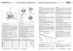
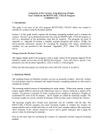
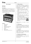
1
AMx58x P
2 – Identification
User Manual
The device can be identified by the label’s data
(ordering code, serial number). This information is
listed in the delivery document. The technical
features of the product can be determined by the
ordering code.
AMx58x P
Description
Lika’s Programmable Encoder is designed to be a
very flexible replacement for any absolute encoder
version with parallel or serial SSI output. The
encoder can be easily programmed via RS232
interface using any common terminal software (e.g.
Hyper Terminal®).
File: E211871
3 – Installation
Install the device according to the protection level
provided.
Protect it against knocks, dust, solvents and
extreme temperatures.
4 – Mounting steps
In order to guarantee the maximum life of
mechanical parts of the encoder, we recommend to
use a flexible coupling between the encoder and
the motor shaft.
IMPORTANT: You are strongly recommended not
to carry out any mechanical operations (drilling,
milling…) on the encoder’s shaft. This could cause
serious damage to the internal parts and the
immediate warranty loss.
Contents
1
2
3
4
5
6
7
Safety summary
Identification
Installation
Mounting steps
Electrical Connections
Functions and settings
Dimensional drawing
1 - Safety summary
•
Safety instructions serve for the protection of
health and safety standards at work and the
prevention of accidents. Please observe them
strictly.
• Your device has been quality controlled, tested
and it’s ready for use. Please respect all
information and advices which are on the
device and on this manual.
• Work on this device must only be carried out by
qualified personnel.
• Repairs should be carried out only at our
factory. If any information is missing or unclear,
please contact the LIKA’s sales staff.
MAN AMx58x P I_E 1.5
5 – Electrical connections
We recommend to follow the instructions below:
• This device is to be supplied by a Class 2 Circuit
or Low-Voltage Limited Energy or Energy
Source not exceeding 30 Vdc.
• While connecting, power must be switched OFF.
• Check correct lines and connections before
switching ON the device.
• We recommend that the device has to be
mounted as far as possible from any capacitive
Pag. 9/16
www.lika.it
www.lika.biz
AMx58x P
•
•
•
•
•
•
or inductive noise source such as motors, relays
and switching devices.
Avoid routing the cable near high voltage
power cables in order to reduce influences of
electric noise.
Only use shielded cables and wire with a cross
section between 0,14mm2 and 0,5 mm2.
The shield of the cable and 0Vdc wire should be
connected to ground (GND).
Electric noise sources should be linked with
noise suppression filters.
Total length of connection cable from should
not exceed 50 m (55').
Connect according the pin-out supplied.
E41MLS (41 pin standard connector)
Pin
Function
Pin
Function
A
B
C
D
E
F
G
H
J
K
L
M
N
P
R
S
T
U
V
W
X
Out 1(LSB)
Out 2
Out 3
Out 4
Out 5
Out 6
Out 7
Out 8
Out 9
Out 10
Out 11
Out 12
Out 13
Out 14
Out 15
Out 16
Out 17
Out 18
Out 19
Out 20
Out 21
Y
Z
a
b
c
d
e
f
g
h
i
j
k
m
n
p
q
r
s
t
Out 22
Out 23
Out 24
Out 25 (MSB)
Parity bit
Zero setting
Latch
TxD
RxD
GND (RxD, TxD)
Tristate
Reset
Preset 1
Preset 2
n.c.
n.c.
n.c.
Complementary
+10Vdc +30Vdc
0Vdc GND
E32MLS (option "V", 32 pin connector)
Pin
Function
Pin
Function
A
B
C
D
E
F
G
H
J
K
L
M
Out 1(LSB)
Out 2
Out 3
Out 4
Out 5
Out 6
Out 7
Out 8
Out 9
Out 10
Out 11
Out 12
T
U
V
W
X
Y
Z
a
b
c
d
e
Out 17
Out 18
Out 19
Out 20
Out 21
Out 22
Out 23
Out 24
Out 25 (MSB)
Parity bit
Zero setting
Latch
MAN AMx58x P I_E 1.5
N
P
R
S
Out 13
Out 14
Out 15
Out 16
f
g
h
j
TxD
RxD
+10Vdc +30Vdc
0Vdc GND
EML121 (12 pin connector, SSI output)
Pin
Function
Pin
Function
1
2
3
4
5
6
clock clock +
data +
data TxD
RxD
7
8
9
10
11
12
Zero setting
Complementary
Preset 1
Preset 2
+10Vdc +30Vdc
0Vdc GND
40 wires cable
Colour
Function
Colour
Function
brown
red
pink
yellow
green
blue
violet
grey
white
black
brown/red
white/red
blue/red
pink/grey
white/yellow
brown/green
white/green
yellow/brown
white/blue
brown/blue
Out 1(LSB)
Out 2
Out 3
Out 4
Out 5
Out 6
Out 7
Out 8
Out 9
Out 10
Out 11
Out 12
Out 13
Out 14
Out 15
Out 16
Out 17
Out 18
Out 19
Out 20
white/pink
white/grey
pink/brown
grey/brown
brown/black
white/black
grey/green
yellow/grey
pink/green
yellow/pink
green/blue
yellow/blue
green/red
yellow/red
green/black
yellow/black
pink/blue
grey/red
pink/red
grey/blue
Out 21
Out 22
Out 23
Out 24
Out 25 (MSB)
Parity bit
Zero setting
Latch
TxD
RxD
GND (RxD, TxD)
Tristate
Reset
Preset 1
Preset 2
n.c.
n.c.
Complementary
+10Vdc +30Vdc
0Vdc GND
16 wires cable, SSI output
Colour
Function
Colour
Function
brown
red
pink
yellow
green
blue
violet
clock +
clock data +
data TxD
RxD
Preset 1
grey
black
white
red/blue
pink/grey
white/yellow
yellow/brown
Preset 2
GND (RxD, TxD)
Reset
Zero setting
Complementary
+10Vdc +30Vdc
0Vdc (GND)
6 - Functions and settings
6.1 Function of inputs
Reset (active at 0Vdc GND)
Resets all the last encoder’s parameters memorized.
Zero setting (Datum value)
Sets the encoder's actual position to zero (0) and
includes previously set offset value (see OFST
parameter).
Pag. 10/16
www.lika.it
www.lika.biz
AMx58x P
Input <8Vdc : encoder not enabled (Tristate not
activated).
New actual position = 0 + Offset.
Input has to be active min. 3,5 µs.
Input >10Vdc : zero setting (min. 3,5µs)
Input <8Vdc : function not enabled
Complementary (counting direction)
Allows to change counting direction by means of
an input signal. Status of the input is checked only
while switching on the encoder.
Input >10Vdc : counter clockwise counting
Input <8Vdc : clockwise counting (standard)
RXD, TXD (RS232)
Serial interface port for parameter settings and
data read-out.
RS232 parameters:
Baud rate = 9600 baud
Data = 8 bit, stop=1 bit
Flux control = Xon/Xoff
Parity
Allows to control functioning of encoder outputs
and connection integrity. Parity bit output is active
(high) when the sum of active output bits (high) in
even or odd (see parameter |EVEN and |ODD).
Latch
Allows the storage of the position value which the
encoder shows in output at a particular moment.
The above mentioned position value will remain
present in output until the LATCH signal is
deactivated. In this way it is possible, if for instance
the data transmission speed of the encoder is fast
in comparison to the data acquisition time of the
interface electronics, to freeze the position for the
amount of time necessary for the data to be
acquired.
Input >10Vdc: position freezed (Latch activated)
Input <8Vdc: Latch not activated
Tristate
Allows the transmission of output information
from the encoder to be blocked. In this it is possible
to work with several encoder in parallel
(multiplexing) using a single control unit, acquiring
the information values relative to the angular
position of each encoder with an updating time
equal to the duration of the multiplexing cycle.
Input >10Vdc : encoder enabled (Tristate activated)
MAN AMx58x P I_E 1.5
Preset1/Preset2
The Preset1 and Preset2 inputs are necessary for
the teach-in function of encoder resolution (see
PRST1 and PRTS2 parameters).
Input >10Vdc : teach-in activated
Input <8Vdc : teach-in not activated
6.2 RS232 communication
To start communication between encoder and PC
run the file Lika_com.ht* or set-up connection
parameters as follows:
(*delivered with encoder and downloadable on
www.lika.biz)
e.g. with Hyper Terminal®
• run Hyper Terminal®
• menu “File” -> “New Connection”
• enter any file name -> press OK
•
•
in “Connect to” window
set “Connect using” to “Direct to Com1” ->
press OK
•
in "Port settings" window set
Bits per second 9600
Data bits
8
Parity
No
Stop bits
1
Flow control
Xon/Xoff
•
•
•
•
•
•
•
•
menu “File” -> “Properties”
select “Settings” folder
set tag on “Terminal keys”
parameter “Emulation” select “VT100”
enter in “ASCII Setup”
set “Line Delay” to value 100
set “Character Delay” to value 10
set tag “Force incoming data to 7-bit ASCII”
NOTE: A complete sequence of commands can be
saved as a text file (.txt) and sent directly to the
encoder.
e.g. Hyperterminal®
menu “Transfer” -> “Send Text File”
Pag. 11/16
www.lika.it
www.lika.biz
AMx58x P
6.3 Communcation commands list
|DEV (1, 127) "DEVice"
Sets device address of the encoder. If several
encoders are connected to network it is necessary
to set a different device address to each encoder
separately. Communication can be activated by
|ADDR command.
Default: 0
Syntax: |DEV=xxx
Value range: from 1 to 127
|ADDR (1, 127) "ADDRess"
Activates communication with a certain encoder
(address must be previously assigned by |DEV
command)
Syntax: |ADDR=xxx (where xxx=encoder address)
At prompt ">" encoder is ready to receive
commands from the PC. To open a communication
channel with another encoder it is necessary to
exclude the previous one.
Note: Each Lika's programmable encoder accepts
address zero (0), which allows to communicate
even if the real address is unknown.
|RST "ReSeT"
Resets all encoder parameters to default condition
(factory setting).
Syntax: |RST
6.4 Encoder output settings
|BIN "BINary"
Sets Binary output code (default setting).
Syntax: |BIN
|GRAY "GRAY"
Sets Gray output code.
Syntax: |GRAY
|BCD “BCD”
Sets BCD output code.
Syntax: |BCD
|NS (1, 4096 o 8192) "Number of Steps"
Sets single turn resolution (counts per revolution).
NOTE: Resolution cannot be set higher than
physical encoder resolution (4096 CPR if
AMx58x12… or 8192 CPR if AMx58x13…).
Syntax: |NS=xxxx
Value range: from 1 to 4096 or 8192 (see note)
|NR (1, 4096) "Number of Revolutions"
Sets multiturn resolution (number of revolutions).
NOTE: Resolution cannot be set higher than
physical encoder resolution.
Syntax: |NR=xxxx
Value range: from 1 to 4096
ATTENTION: Do not exceed the number of
revolutions programmed to avoid rounding error.
Rounding error
When you program number of revolutions which is
not a sub multiple of 4096, a rounding error will
occur when you overtake the encoder’s cycle (4096
rev.).
MAN AMx58x P I_E 1.5
Pag. 12/16
www.lika.it
www.lika.biz
AMx58x P
Example 1
Desired nr. of revolutions = 6
Encoder cycles = 4096 / 6 = 682,666…
This means that the encoder has to complete 4096
physical revolutions within 682,6 cycles. As this is
not an integer number, a rounding error will occur
after completing the 4096 physical revolution.
The number of revolutions which can be completed
without error are: 6 x 682 = 4092.
After 4096 physical revolutions the Encoder will
show zero position.
Therefore the rounding error will be 4096 - 4092 =
4 rev.
Example 2
Desired nr. of revolutions = 4
Encoder cycles = 4096 / 4 = 1024
The number of revolutions which can be completed
without error are: 4 x 1024 = 4096
Rounding error will be 4096 - 4096 = 0 rev.
|POFF “Parity bit OFF”
Parity bit disabled
Syntax : |POFF
|ZERO "ZERO setting"
Sets actual encoder position to zero (0). Zeroing
includes previously set offset values (OFST). See also
chapter 6.1 "Zero setting"
Syntax: |ZERO
|OFST (0, |NS x |NR) "OffSeT"
Sets offset value (e.g. tool correction). This value is
added to actual value.
Note: To be active this command has to be sent
before zeroing the encoder.
Syntax: |OFST=x
Value range: from 0 to NS x NR (total resolution).
|CLW "ClockWise"
Sets clockwise counting sequence seen from shaft
side (default setting).
Syntax: |CLW
see also |EXTD command!
6.5 Teach-in function
Teach-in function allows the encoder to set the
needed resolution along the measurement length
itself.
Syntax: |PRST1=x / |PRST2=x
Value range: from 0 to NS x NR (total resolution).
Step by step procedure:
• determine to end points along the
measurement length (Start e Stop);
• determine the desired resolution along the
measurement length (total resolution encoder
has to show from Start to Stop)
• (e.g. 1000 positions);
• set start position by |PRST1 command (e.g.
|PRST1=100);
• set stop position by |PRST2 command (e.g.
|PRST2=1100).
|CCLW "CounterCLockWise"
Sets counter-clockwise counting sequence seen
from shaft side.
Syntax: |CCLW
see also |EXTD command!
|EXTD "EXTernal Direction"
Enables hardware complementary input (default).
See chapter 6.1 "Complementary (counting
direction)"
If the counting direction is set by software
command (|CLW, |CCLW), the hardware
complementary input will be disabled until a new
|EXTD command is send.
Syntax : |EXTD
|EVEN "Parity bit EVEN"
Sets parity bit even. Parity bit will be logic level low
when the sum of output bits with logic level high is
even.
Syntax : |EVEN
MAN AMx58x P I_E 1.5
|ODD "Parity bit ODD"
Sets parity bit odd. Parity bit will be logic level low
when the sum of output bits with logic level high is
odd.
Syntax : |ODD
Preset1
1)
2)
Preset2
Start
Stop
1) beginning of teach-in / 2) end of teach-in
Pag. 13/16
www.lika.it
www.lika.biz
AMx58x P
•
move encoder next to Start position and
activate Preset1 input (high).
• move encoder to Start position and activate
Preset2 input (high).
• move encoder along the measurement length
until Stop position.
• deactivate Preset1 input (low) when encoder
reached Stop position.
• after gear factor calculation encoder will show
the actual value of Stop position (1099*).
• deactivate Preset2 input (low) to terminate
teach-in procedure.
(* as result of the above example the measurement
length is 1000 steps, from position 100 to 1099).
ATTENTION:
• the desired resolution cannot exceed physical
resolution (4096 x 4096 or 8192 x 4096);
• do not pass zero position while teaching-in;
Zeroing on Start position is recommended;
• counting sequence has to be positive from
Start to Stop positions;
If any error occurs while teaching-in the encoder
will deactivate all outputs (level low).
6.6 Serial interface messages
Symbol
Message
>
correct comunication
?
command error
!
value out of range
MAN AMx58x P I_E 1.5
Pag. 14/16
www.lika.it
www.lika.biz
AMx58x P
7 - Dimensional drawing
7.2 AM58S P
7.1 AM58 P
7.3 AMC58 P
MAN AMx58x P I_E 1.5
Pag. 15/16
www.lika.it
www.lika.biz
AMx58x P
Lika Electronic
Via S. Lorenzo, 25 – 36010 Carrè (VI) - Italy
Tel. +39 0445 382814
Fax +39 0445 382797
Italy: eMail [email protected] - www.lika.it
World: eMail [email protected] - www.lika.biz
MAN AMx58x P I_E 1.5
Pag. 16/16
www.lika.it
www.lika.biz