1
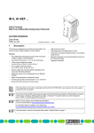
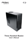
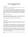
Ax58x ProfibusDP
User manual
Ax58x PB
CCPB, CCPBC
Chapters
1
2
3
4
5
Safety summary
Identification
Quick reference (STEP7)
Electrical connections
Profibus interface
Profibus+DP Profile for Encoders
1 Safety summary
Safety
• observe the professional safety and accident prevention regulations applicable to your
country during device installation and operation;
• installation has to be carried out by qualified personnel only, without power supply and
stationary shaft;
• the encoder must be used only for the purpose appropriate to its design;
• high current, voltage and rotating parts can cause serious or fatal injury.
Electrical safety
• switch OFF the voltage before connecting the device;
• connect according to the chapter 4: “Electrical connections”;
• according to the 89/336/CEE norm on electromagnetic compatibility, following
precautions must be taken:
+ before handling and installing, discharge electrical charge from your body and tools which
may come in touch with the device;
+ power supply must be stable without noise, install EMC filters on device power supply if
needed;
+ always use shielded and twisted cables if possible;
+ avoid cables runs longer than necessary;
+ avoid running the signal cable near high voltage power cables;
+ mount the device as far as possible from any capacitive or inductive noise source, shield the
device from noise source if needed;
+ minimize noise by connecting shield or connector housing to ground (GND). Make sure that
ground (GND) is not affected by noise. The shield connection point to ground can be
situated both on the device side and on user’s side. The best solution to minimize the
interference must be carried out by the user.
Mechanical safety
• solid shaft: use a flexible coupling to connect encoder to motor shaft respecting the
coupling misalignment tolerances;
• do not disassemble the encoder;
• do not tool the encoder or its shaft;
• do not subject the encoder and the shaft to knocks or shocks;
• respect the environmental characteristics of the product.
MAN Ax58x PB E 2.1.doc
Pag.1
www.lika.it
www.lika.biz
Ax58x ProfibusDP
2 Identification
The device can be identified by the label's data (ordering code, serial number).
This information is listed in the delivery document. For technical features of the
product, refer to the technical catalogue.
File E211871
3 Quick reference
3.1 STEP7 configuration
Import GSD file
Profibus encoders are supplied with a GSE file LIKA1655.GSE (see enclosed
support or www.lika.biz > PRODUCTS > ROTACOD > Ax58x PB).
In the “HW Config” window, select “Options > Install GSD file…”.
Select the correct GSD file in the installation window and install it.
MAN Ax58x PB E 2.1.doc
Pag.2
www.lika.it
www.lika.biz
Ax58x ProfibusDP
Adding a node to a project
In the “HW Config” window, select “Catalog > PROFIBUS_DP > Additional Field
Devices > Encoders”, drag “ROTACOD AM58” module and connect it to “BUS”.
Drag the desired submodule (Class 1 or Class 2) on the variables table to set the
class of the device (for more details see chap.5.2).
Encoder configuration parameters
To enter the Encoder configuration parameters window, select the device in the
"HW Config" window and right click the mouse.
Click on "Object Properties…".
MAN Ax58x PB E 2.1.doc
Pag.3
www.lika.it
www.lika.biz
Ax58x ProfibusDP
A window will appear with a list of all encoder parameters.
For Information on correct use and settings reefer to chapter 5.4
Class 1 example
Class 2 example
Click the “OK” and then “Download” button to store the parameters.
MAN Ax58x PB E 2.1.doc
Pag.4
www.lika.it
www.lika.biz
Ax58x ProfibusDP
3.2 Reading diagnostic information
The diagnostic information message can be set either to 16 or 63 bytes, see
“Diagnostic type” in encoder parameters.
To view the diagnostic information, the encoder must be on+line:
click “online<+>offline” button or select “Station > Open online”.
Select “PLC > Module information…” the following window will appear:
Click “Hex Format…” button to display diagnostic information:
MAN Ax58x PB E 2.1.doc
Pag.5
www.lika.it
www.lika.biz
Ax58x ProfibusDP
6 bytes diagnostic:
Byte
0
1
2
3
4
5
MAN Ax58x PB E 2.1.doc
Description
status 1
status 2
status 3
Master ID
manufacturer ID
Pag.6
www.lika.it
www.lika.biz
Ax58x ProfibusDP
3.3 Setting the Preset value
Example:
The encoder with device address 1 transmits the position value to the Master.
The position value is loaded into variables ED 100…103 (4 byets).
The Preset is transmitted using variables AD 100…103 (4 bytes).
•
Encoder actual position is 0000 2268hex
•
•
to set Preset value = 0000 0500hex
Set bit 31 of variable AD 100 = “1” (8000 0500hex)
•
click "Command" button:
Now the position value is 0000 0500hex.
To close Preset procedure
• set bit 31 of variable 100 back to ”0”
• click "command" button
NOTE:
Some releases of STEP7 may not work properly with Data variables having index
higher than 127. We recommend to use "MD" reference operators (pointers) for
encoder position, velocity and Preset.
MAN Ax58x PB E 2.1.doc
Pag.7
www.lika.it
www.lika.biz
Ax58x ProfibusDP
4 Electrical connections
ATTENTION: do not remove or mount the connection cap with power supply
switched ON. Damage may be caused to internal components. Make sure that
the encoder body and connection cap are at the same potential.
Minimize noise by connecting shield or connector housing to ground (GND).
Make sure that ground (GND) is not affected by noise. It’s recommended to
provide the ground connection as close as possible to the encoder.
4.1 Connection cap with PGs (CCPB)
OUT
IN
The CC+PB connection cap has 3 cable gland PG9 for bus+IN, bus+OUT
connections and for power supply connection. The bus cables can be connected
directly to the clamps placed in front of each cable gland.
It's recommended to use Profibus+DP certificated cables. Core diameter should
not exceed Ø1,5mm (0.06inch).
Clamp
+
+
B
A
PG
Description
0 Vdc Supply voltage
+10Vdc +30Vdc Supply voltage
Profibus B (Red)
Profibus A (Green)
Shield 1
1
: connected cable shield to cable gland.
MAN Ax58x PB E 2.1.doc
Pag.8
www.lika.it
www.lika.biz
Ax58x ProfibusDP
4.2 Conn. cap with M12 connectors (CCPBC)
The CC+PB+C connection cap has three M12 connectors with pin+out according
to the Profibus standard. Users can directly connect Profibus cables for
commerce.
Power supply:
connector: M12
coding: A
(frontal side)
Pin
1
3
4
Profibus signals:
connector: M12
coding: B
(frontal side)
Pin
2
4
male
Function
+10Vdc +30Vdc
0 Vdc GND
Shield
male
female
(BUS IN)
(BUS OUT)
Function
Profibus A (Green)
Profibus B (Red)
4.3 Bus termination
A bus termination resistance is provided in the connection cap. This has to be
activated as line termination on the last device.
Use RT Switch activated or deactivate the bus termination.
RT
1 = 2 = ON
1 = 2 = OFF
Description
Activated: if the encoder is the last device
Deactivated: if the encoder is not the last device
4.4 Baud rate
The baud rate can be set by the Master via software during configuration of the
node (slave).
Supported baud rates are listed in the .GSD file.
MAN Ax58x PB E 2.1.doc
Pag.9
www.lika.it
www.lika.biz
Ax58x ProfibusDP
4.5 Node number: DIP A
The node number must be set via hardware using dip+switches DIP A.
Permissible addresses are from 0 to 125.
Power supply must be switched off during this operation.
DIP A:
Set the node number in binary value: ON=1, OFF=0
bit
1
LSB
20
2
3
4
5
6
21
22
23
24
25
7
MSB
26
8
not
used
Example:
Set node number = 25:
2510 = 0001 10012 (binary value)
bit
1
2
3
4
5
6
7
8
0
1
2
3
4
5
6
2
2
2
2
2
2
2
ON OFF OFF ON ON OFF OFF OFF
Set node number = 55:
5510 = 0011 01112 (binary value)
bit
1
2
3
4
5
6
7
8
0
1
2
3
4
5
6
2
2
2
2
2
2
2
ON ON ON OFF ON ON OFF OFF
4.6 LED diagnostics
Two LEDs on the rear of the connection cap show the status of the Profibus+DP
interface.
Fault (red)
OFF
OFF
OFF
ON
ON
Flashing
Flashing
Power (green)
OFF
ON
Flashing
Flashing
OFF
ON
Flashing
MAN Ax58x PB E 2.1.doc
Event
No power supply or hardware malfunction
Correct function (correct communications)
Dead Zone, see chap. 5.8
Configuration parameter not valid
Transmission time+out error
Bus communication failure
Flash memory error
Pag.10
www.lika.it
www.lika.biz
Ax58x ProfibusDP
5 Profibus interface
The unit is a slave device according to “Profibus+DP Profile for Encoders” and it
can be set as Class 1 or Class 2 device (see chapter 5.2).
Refer to the official Profibus website for all information not listed in this
manual (www.profibus.com).
5.1 GSD file
Profibus encoder is supplied with GSE file LIKA1655.GSE (see enclosed support
or www.lika.biz > PRODUCTS > ROTACOD > Ax58x PB). Install GSE file on
Profibus master device.
5.2 Classes of the Device profile
Encoder class must be set during configuration of the device. Class 1 allows
basic functions of the device and should be used for:
• transmission of position value
• change of counting direction
• Preset value
Class 2 allows to use Class 1 functions and extended function such as:
• scaling function
5.3 Modes of operation
Profibus+DP devices allow operation using different communication modes (see
figure below):
Power+ON
Set_Prm_FAIL
Chk_Cfg_FAIL
Init_OK
Wait_Prm
Set_Prm_OK
Wait_Cfg
Chk_Cfg_OK
Data_Exchange
NOTE:
All parameters except Preset value are transmitted in Set_Prm mode.
Preset value is transmitted only in Data_Exchange mode.
MAN Ax58x PB E 2.1.doc
Pag.11
www.lika.it
www.lika.biz
Ax58x ProfibusDP
Types of communication
Transmission of data between Master and Slave takes place using the following
3 types of messages:
•
DDLM_Set_Prm:
Used for configuration of the slave. This mode is active immediately after
power ON and used to transmit parameters from the Master to the Slave
(see chapter 5.4).
•
DDLM_Chk_Cfg:
Defines the number of bytes used for data transmission in Data_Exchange
mode (see chapter 5.5).
•
DDLM_Data_Exchange:
Used as "standard operation mode".
Used by the Master to send the Preset value and used by the Slave to
transmit position value (see chapter 5.6).
•
DDLM_Slave_Diag:
Used during power on and whenever the Master wants to know diagnostic
information from the Slave device (see chapter 5.7).
5.4 DDLM_Set_Prm
It is possible to choose between different encoder configurations. Functionality
and parameters depend on the selected configuration and are stored in the
Master.
At start+up the Profibus network transmits all data to the Slave (DDLM_Set_Prm
mode).
The following tables shows the structure of parameters according to the
encoder Profile.
DDLM_Set_Prm with Class 2:
Byte
0…9
10
11…12
13…16
17…20
MAN Ax58x PB E 2.1.doc
bit 0
bit 1
bit 2
bit 3
bits 4…7
Parameter
reserved for PROFIBUS
operating parameters
code sequence
class 2 functionality
reserved
scaling function control
reserved
counts per revolution
total resolution
reserved
Pag.12
www.lika.it
www.lika.biz
Ax58x ProfibusDP
5.4.1 Byte 10 Operating parameters
Bit
0
1
2
3
4, 5, 6, 7
Function
code sequence
class 2 functionality
reserved
scaling function control
reserved
bit = 0
CW
disabled
bit = 1
CCW
enabled
disabled
enabled
Code sequence
The code sequence defines whether increasing or decreasing position values are
output when the encoder shaft rotates clockwise (CW) or counterclockwise
(CCW) as seen from the shaft side.
The code sequence is set with the code sequence bit in the operating
parameters.
Class 2 functionality
Disabled = Encoder Class 1 is set.
Enabled = Encoder Class 2 is set.
Scaling function control
If disabled the device uses the hardware resolution, if enabled the device uses
the resolution transmitted in bytes 11…16 (Counts per revolution and Total
resolution).
For a correct use of this function see chapter 5.4.2 and 5.4.3.
5.4.2 Bytes 11…12 Counts per revolution
The “Counts per revolution” parameter can be used to program a user specific
resolution each turn (single turn resolution).
The function is active if :
bit 1 and bit3 of byte 10 are =”1”
Byte
Bits
Data
11
15+8
15
2 to 28
12
7+0
7
2 to 20
Possible values are equal or less than “hardware counts per revolution”.
Setting a value greater than possible, the resolution will be forced to “hardware
counts per revolution”.
MAN Ax58x PB E 2.1.doc
Pag.13
www.lika.it
www.lika.biz
Ax58x ProfibusDP
5.4.3 Bytes 13…16 Total resolution
This parameter is used to adapt the measuring range of encoder to a different
measuring range required by the application.
The function is active if :
bit 1 and bit3 of byte 10 are =”1”
Byte
Bit
Data
13
31+24
31
2 to 224
14
23+16
23
2 to 216
15
15+8
15
2 to 28
16
7+0
7
2 to 20
Possible values are equal or less than “hardware total resolution”.
Setting a value greater than possible, the resolution will be forced to “hardware
total resolution”.
“total resolution ”
“Number of rev.”=
“counts per revolution ”
It's recommended to set “Number of revolution” to a value which is power of 2.
This avoids problems when using the device in endless operation (when passing
the physical zero) and entering the "Dead Zone" (see chapter 5.8).
Example
“AS5813/PB+xx”: singleturn encoder
• “Hardware counts per revolution” = 13 bit/turn (8192 cpr)
• “Hardware number of turns”
=1
• “Hardware total resolution”
= 13 bit (8192 ∗ 1 = 8192)
“AM5812/4096PB+xx”: multiturn encoder
• “Hardware counts per revolution” = 12 bit/turn (4096 cpr)
• “Hardware number of turns”
= 12 bit (4096 turn)
• “Hardware total resolution”
= 24 bit (4096 ∗ 4096 = 16777216)
Example
Multiturn encoder “AM5812/4096PB+6” with connection cap “CC+PB+C“.
Resolution is:
• “Hardware counts per revolution” = 4096 (2^12)
• “Hardware number of turns”
= 4096 (2^12)
• “Hardware total resolution”
= 16777216 (2^24)
2048 steps per revolution ∗ 1024 turns are required:
• Enable “scaling function”:
byte 10 = 0A hex (bit 1 = bit 3 = “1”)
• “Counts per revolution” = 2048: byte 11…12 = 0800 hex
• “Total resolution” = 2048 ∗ 1024 = 2097152: byte 13…16 = 0020 0000 hex.
NOTE:
If “counts per revolution” and/or “total resolution” are changed, the Preset value
should be adapted to the new resolution. A new setting to the Preset value is
also required.
MAN Ax58x PB E 2.1.doc
Pag.14
www.lika.it
www.lika.biz
Ax58x ProfibusDP
5.5 DDLM_Chk_Cfg
The configuration function allows the Master to send configuration data to the
Slave for checking. The main purpose of this function is to define number of
bytes used for the Data_Exchange as seen from the Master side.
Chk_Cfg message structure (1 byte):
bit 7
bit 6
bit 5…4
bit 3…0
= Concistency (=”1”)
= Word format (“0”=byte,“1”=word=4byte)
= In/out data (“01”=Input, ”10”=output)
= Length code
Example:
bit
Data
7
1
1
6
1
1
5
0
1
4
1
0
3
0
0
2
0
0
1
0
0
0
1
1
D1h
E1h
D1hex = 4 byte input
E1hex = 4 byte output
MAN Ax58x PB E 2.1.doc
Pag.15
www.lika.it
www.lika.biz
Ax58x ProfibusDP
5.6 DDLM_Data_Exchange
This is the normal operation status of the system. The Slave can transmit the
position value and receive the Preset value from the Master (both Class 1 and
Class 2).
Position value (Encoder Master)
Byte
Bit
Data
1
31+24
231 to 224
2
23+16
223 to 216
3
15+8
215 to 28
4
7+0
27 to 20
2
23+16
23
2 to 216
3
15+8
15
2 to 28
4
7+0
7
2 to 20
Preset (Master Slave)
Byte
Bit
Data
1
31+24
31
2 to 224
The preset value is the process actual value, which should then be output when
the axis is in a certain physical position. Using the preset value parameter, the
value output from the angular encoder, is defined at a specific angular position.
+ If “scaling function control” = disable
“Preset” < “hardware total resolution”.
+ If “scaling function control” = enable
“Preset” < “total resolution”.
The preset value is transferred in the Data_Exchange mode (from Master to
Slave) by setting bit 31 = “1” at last 3 cycles .
Example:
Preset to set = 0000 1000hex
actual position = 0005 5000hex
Byte
Bit
1
31+24
2
23+16
3
15+8
4
7+0
1°
MS
SM
80
00
00
05
10
50
00
00
2°
MS
SM
80
00
00
05
10
50
00
00
3°
MS
SM
80
00
00
00
10
10
00
00
Cycle
We suggest to set preset with stationary shaft.
The new preset value is stored immediately after reception.
MAN Ax58x PB E 2.1.doc
Pag.16
www.lika.it
www.lika.biz
Ax58x ProfibusDP
5.7 DDLM_Slave_Diag
The Master device can request diagnostic information at any time to the Slave
device.
6 bytes Diagnostic:
Byte
0
1
2
3
4
5
MAN Ax58x PB E 2.1.doc
Description
status 1
status 2
status 3
Master ID
manufacturer ID
Pag.17
www.lika.it
www.lika.biz
Ax58x ProfibusDP
5.8 "Dead Zone"
The "Dead Zone" occurs when
“Number of revolution” =
“total resolution ”
is not a power of 2.
“counts per revolution ”
The device operates in the "Dead Zone" for the remaining positions to complete
the difference between “hardware total resolution” and “total resolution” when
this difference is less than “total resolution”.
Example:
“AM5813/4096PB+xx”: multiturn encoder
• “hardware counts per revolution” = 8192 (2^13)
• “hardware number of turns”
= 4096 (2^12)
• “hardware total resolution”
= 33554432 (2^25)
set parameters value:
• “Counts per revolution”
= 5 000
• “Number of revolution”
= 2 000
• “Total resolution”
= 10 000 000
“hardware number of revolution ” 4096
=
= 2.048
“number of revolution ”
2000
hence, for 96 revolutions (4096 + 2 ∗ 2000 = 96) the encoder will work inside
the "Dead Zone".
It can be explain graphically:
transmitted
position
total resolution
hardware total
resolution
red
zone
position
NOTE:
• The Dead Zone status is indicated with green LED flashing and red LED OFF.
• In Dead Zone, the transmitted position is coherent with setting resolution: it
is calculating so that the last position before zero position is “Total
resolution +1”.
• Make attention using encoder position if it work in Dead Zone. In passage
from normal status to Dead Zone status (and vice versa) a jump of position
occurs.
MAN Ax58x PB E 2.1.doc
Pag.18
www.lika.it
www.lika.biz
Ax58x ProfibusDP
MAN Ax58x PB E 2.1.doc
Pag.19
www.lika.it
www.lika.biz
Ax58x ProfibusDP
Man.Vers.
1.0
2.0
2.1
Description
1st issue
General revision
Chapter 4 update
This device is to be supplied by a Class 2 Circuit or Low+
Voltage Limited Energy or Energy Source not exceeding 30
Vdc. Refer to the product datasheet for supply voltage rate.
LIKA Electronic
Via S. Lorenzo, 25 + 36010 Carrè (VI) + Italy
Tel. +39 0445 382814
Fax +39 0445 382797
Italy: eMail [email protected] + www.lika.it
World: eMail [email protected] + www.lika.biz
MAN Ax58x PB E 2.1.doc
Pag.20
www.lika.it
www.lika.biz