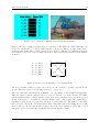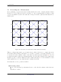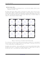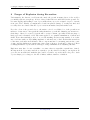
1
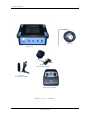
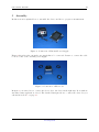
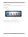
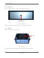
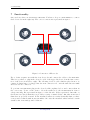
Future Series Geoseeker 8 User’s manual User’s manual: Geoseeker 2 Any information contained in these operating instructions may be changed without prior notice. OKM does not make any warranty for this document. This also applies without limitation to implied assurances of merchantability and fitness for a specific purpose. OKM does not assume any responsability for errors in this manual or for any incidental or consequential damage or loss associated with the delivery, exploitation or usage of this material. This documentation is available as presented“ and without any kind of warranty. In no circumstances OKM ” takes responsibility for lost profits, usage or data losts, interruption of business activities or all kind of other indirectly damages, which developed because of errors in this documentation. This instruction manual and all other stored media, which are delivered with this package should only be used for this product. Program copies are allowed only for security- and savety purposes. The resale of these programs, in original or changed form, is absolutely forbitten. This manual may not be copied, duplicated or translated into another language, neither in part nor completely, over the copyright matters without the prior written consent of OKM. Copyright © 2005 OKM Ortungstechnik GmbH. All rights reserved. OKM Ortungstechnik GmbH www.okm-gmbh.de Contents 3 Contents 1 Preface 2 Important Notes 2.1 General Notes . . . . . . 2.2 Possible Health Hazards 2.3 Surrounding Area . . . . 2.4 Voltage . . . . . . . . . 5 . . . . 6 6 6 6 6 3 Technical Specifications 3.1 Control Unit . . . . . . . . . . . . . . . . . . . . . . . . . . . . . . . . . . . . . . 7 7 4 Scope of Delivery 8 . . . . . . . . . . . . . . . . . . . . . . . . . . . . . . . . . . . . . . . . . . . . . . . . . . . . . . . . . . . . . . . . . . . . . . . . . . . . . . . . . . . . . . . . . . . . . . . . . . . . . . . . . . . . . . . . . . . . . . . . . . . . 5 Assembly 10 6 Control Elements 6.1 Front View . . . . . . . . . . . . . . . . . . . . . . . . . . . . . . . . . . . . . . . 6.2 Back View . . . . . . . . . . . . . . . . . . . . . . . . . . . . . . . . . . . . . . . . 6.3 Top Side . . . . . . . . . . . . . . . . . . . . . . . . . . . . . . . . . . . . . . . . . 11 11 12 12 7 Functionality 7.1 Proceeding for a Measurement . . . . . . . . . . . . . . . . . . . . . . . . . . . . 13 15 8 Danger of Explosion during Excavation 17 9 Maintenance and Services 18 OKM Ortungstechnik GmbH www.okm-gmbh.de User’s manual: Geoseeker 4 List of Figures 1 2 3 4 5 6 7 8 9 10 11 Scope of Delivery . . . . . . . . . . . . . . . . . . . . Connection of External Power Supply . . . . . . . . Connection of Electrodes . . . . . . . . . . . . . . . . Front View . . . . . . . . . . . . . . . . . . . . . . . Back View . . . . . . . . . . . . . . . . . . . . . . . . Monitor . . . . . . . . . . . . . . . . . . . . . . . . . Connection of Electrodes . . . . . . . . . . . . . . . . Proceeding for a Measurement and Manual Scanning Overview about all values of one measurement . . . Overview about measured values without anomaly . Overview about measured values with anomaly . . . . . . . . . . . . . . . . . . . . . . . . . . . . . . . . . . . . . . . . . . . . . . . . . . . . . . . . . . . . . . . . . . . . . . . . . . . . . . . . . . . . . . . . . . . . . . . . . . . . . . . . . . . . . . . . . . . . . . . . . . . . . . . . . . . . . . . . . . . . . . . . . . . . . . . . . . . . . . . . . . . . . . . . . . . . . . . . . . . 9 10 10 11 12 12 13 14 14 15 16 Technical Specifications (Control Unit) . . . . . . . . . . . . . . . . . . . . . . . . Scope of Delivery . . . . . . . . . . . . . . . . . . . . . . . . . . . . . . . . . . . . 7 8 List of Tables 1 2 OKM Ortungstechnik GmbH www.okm-gmbh.de 1 1 Preface 5 Preface Dear customer, in the first instance we want to thank you that you made your decision on a product of OKM Ortungstechnik GmbH. The present product is based on a geo-electric measuring method which can be used to locate cavities in the target area. This is including not only natural but also man-made cavities. Also metals can be detected with Geoseeker. With our team of specialists we guarantee that our products are under recurrent control. Our specialists try to implement new developments in terms of further quality improvements for you. Of course by selling our products we cannot guarantee that you really make a find during your research. The recognition of hidden objects and structures depends on a hugh number of factors - like you know. Determining factors are the dielectricity constant of the ground, the grade of mineralisation and the dimensions of an object relating to its depth. Specially in very wet soil, clay and sand with high conductivity of the ground, recording of the measured results can be falsified strongly. With this product you purchased a device which stood the tests in regular operation like all other products of us. If you are interested in where our devices have gone into action please visit our homepage. For our company it is necessary that we protect our developments within the framework of existing legislation to a patent or trademark registration. Therewith we offer you a higher warranty while using our products. Please take your time consecutively, read this user‘s manual and familiarize yourself with the utilisation and operation of this Geoseeker. OKM Ortungstechnik GmbH www.okm-gmbh.de User’s manual: Geoseeker 2 6 Important Notes Please read these operating instructions carefully and closely before using Geoseeker and its accessories! These instructions give information on how to use the device and point out potential sources of danger. 2.1 General Notes Being an electronic device, Geoseeker has to be treated with the caution and care necessary when such devices are used. Any failure to observe the safety precautions given or any use for purposes other than the ones it is conceived for may result in a damage or destruction of the processing unit and connected components. The device will get destroyed if it is opened improperly. 2.2 Possible Health Hazards If used properly the device normally does not pose any health hazards. According to current scientific knowledge, the high-frequency signals are not harmful to the human body on account of their low power. 2.3 Surrounding Area Having been transferred from a cold to a warmer place, the device should not be operated immediately afterwards. Any condensation, which may have formed, might cause the device to get destroyed. Avoid strong magnetic fields, which may occur in places such as near machines or loudspeakers, and avoid using a detector within a radius of 50 meters. 2.4 Voltage The power supply should not be outside the indicated range of values. Only use batteries and rechargable batteries which are included in the scope of delivery. Never use the 230 Volt mains supply. OKM Ortungstechnik GmbH www.okm-gmbh.de 3 Technical Specifications 3 7 Technical Specifications The following technical indications are medial values. During operation small variations are quite possible. 3.1 Control Unit Dimensions (H x W x D) . . . . . . . . . . . . . . . . . . . . . . . . . . . . . . . . . . . 430mm x 150mm x 260mm Weight . . . . . . . . . . . . . . . . . . . . . . . . . . . . . . . . . . . . . . . . . . . . . . . . . . . . . . . . . . . . . . . . . . . . . . about 3kg Voltage . . . . . . . . . . . . . . . . . . . . . . . . . . . . . . . . . . . . . . . . . . . . . . . . . . . . . . . . . . . . . . . . . . . . . . . . 12 VDC Processor . . . . . . . . . . . . . . . . . . . . . . . . . . . . . . . . . . . . . . . . . . . . . . . . . . . . . . . . . . . . . Motorola, 4 MHz Operating Temperature Storage Temperature Air Humidity Waterproof . . . . . . . . . . . . . . . . . . . . . . . . . . . . . . . . . . . . . . . . . . . . . . . . . . . . . 0 – 50 . . . . . . . . . . . . . . . . . . . . . . . . . . . . . . . . . . . . . . . . . . . . . . . . . . . . . . -20 – 60 . . . . . . . . . . . . . . . . . . . . . . . . . . . . . . . . . . . . . . . . . . . . . . . . . . . . . . . . . . . . . . . 5% – 75% . . . . . . . . . . . . . . . . . . . . . . . . . . . . . . . . . . . . . . . . . . . . . . . . . . . . . . . . . . . . . . . . . . . . . . . . . No Maximal Penetration Depth . . . . . . . . . . . . . . . . . . . . . . . . . . . . . . . . . . . . . . . . . . . about 40 meters Table 1: Technical Specifications (Control Unit) OKM Ortungstechnik GmbH www.okm-gmbh.de User’s manual: Geoseeker 4 8 Scope of Delivery In the following section you can find all standard equipment. The scope of delivery can be different in some circumstances because of some optional accessories which should not be included in the basic equipment. 1 Control Unit 4 Electrodes (with about 20m cable) 1 Manual 1 External Power Supply 1 Cable for External Power Supply 1 Charger for External Power Supply 1 Carrying Case Table 2: Scope of Delivery Beware that pictures in this manual could be different to delivered parts. OKM Ortungstechnik GmbH www.okm-gmbh.de 4 Scope of Delivery 9 Electrode Control Unit Charger for External Power Supply Cable for External Power Supply External Power Supply Figure 1: Scope of Delivery OKM Ortungstechnik GmbH www.okm-gmbh.de User’s manual: Geoseeker 5 10 Assembly In this section is explained how to assemble the device and how to prepare a measurement. Figure 2: Connection of External Power Supply Figure 2 shows how the external power supply has to be connected. Beware to connect the cable to 12 V socket of the external power supply. Figure 3: Connection of Electrodes In figure 3 you can see how to connect the electrodes to the device in the right way. Do it without any unnecessary application of force! The detailed discription how to connect the electrodes you can find in section 7 on page 13. OKM Ortungstechnik GmbH www.okm-gmbh.de 6 Control Elements 6 11 Control Elements In this section you will learn more about the fundamental use of all control elements for this measuring instrument. All connections, inputs and outputs are explained in detail. 6.1 Front View Figure 4 shows the front side of the device. Power On and Off Button 1 2 3 4 Connection of Electrodes Figure 4: Front View The Power On and Off Button is used to switch on and off the device. Before operating the device you have to be sure that the external power supply is full charged. At the Connection of Electrodes the delivered electrodes has to be connected. OKM Ortungstechnik GmbH www.okm-gmbh.de User’s manual: Geoseeker 6.2 12 Back View Figure 5 shows the back side of the control unit with all connections. Connection of External Power Supply Figure 5: Back View The Connection of External Power Supply is used to connect the external battery. 6.3 Top Side Figure 4 shows the top side of the device. Monitor Figure 6: Monitor On the Monitor all measured results are represented in form of resistance values. OKM Ortungstechnik GmbH www.okm-gmbh.de 7 7 Functionality 13 Functionality On your device there are 4 Connection of Electrodes. You have to keep a certain manner to connect these electrodes in the right way. The correct connection is represented in figure 7. Figure 7: Connection of Electrodes Try to define a square area with the four electrodes and connect the cables to the main unit. Therefore you have to plug in the electrode cable of the upper left electrode in the first connection of the device from left to right. The following electrode cable which is placed next to it counter clockwise has to be plugged into the next connection. Go on in the same direction until all electrodes are connected. To perform a measurement plug in the electrodes like explained above and connect them in the correct way. Power on the devivce. Geoseeker will now do the measurement in form of voltage metering, like represented in figure 8 on the left side. If the represented ohm value on the monitor is reduced than there is probably a cavity or tunnel. If the ohm value is increased than there is probably a metal. If the measured values are nearly identically than you have even ground conditions without any anomalies. Of course the measured values can have certain variances also in normal ground conditions. OKM Ortungstechnik GmbH www.okm-gmbh.de User’s manual: Geoseeker 14 Figure 8: Proceeding for a Measurement and Manual Scanning Figure 9 all values of a single measurement are represented. The numbers 1 until 4 mark the four electrodes, which has to be connected like in figure 7 on page 13. After powering on the device, partial measurements will be realized between every electrode. During one partial measurement the resistance between 2 electrodes will be measured. These values are represented as an example in figure 9. 1r 1 2 1 3 1 2 – – – – – – 3 4 2 4 4 3 = = = = = = 143 145 145 143 146 145 Ω Ω Ω Ω Ω Ω }Ω } 146 r4 @ @ @} @ 143 Ω 145} Ω } 145 Ω 2 r 143} Ω @ @ @ }Ω } 145 @ @r 3 Figure 9: Overview about all values of one measurement The more measured values you have the better you can conclude to possible deposits in the ground. Therefore please read carefully section 7.1 on page 15! After the automatic measurement is finished, you can change to the manual measurement. Therefore please touch the indication Touch screen for manual scan on the monitor. The manual measurement will be realized with the electrodes 1 and 3. Put these electrodes in the ground at any desired place to determine the current resistance value of the ground. The graphical representation on the monitor is represented in figure 8 on the right side. The number on the right side of the arrow shows the current measured value. When this value is increasing the arrow will show to the top. In case this measured value reduces the arrow will show down. The colored line (blue, green, red) represents graphically the current measured value. OKM Ortungstechnik GmbH www.okm-gmbh.de 7 Functionality 7.1 15 Proceeding for a Measurement Before analysing correctly the measured results with the Geoseeker , adequate measured values should be recorded. Therefore it is not enough to do only one measurement. You have to split your area in smaller areas all of the same size. A large area will be split automatically in more smaller parts. r }Ω } r }Ω } r }Ω } r }Ω } r 146 146 142 141 @ @ @ @ @ @ @ @ 142 Ω 141 Ω 141 Ω 142 Ω @} @} @} @} @ @ @ @ @ @ @ @ 146} Ω 145} Ω 144} Ω 144} Ω 147} Ω @ @ @ @ @ @ @ @ 146} Ω 144} Ω 142} Ω 147} Ω @ @ @ @ r }Ω } @r }Ω } @r }Ω } @r }Ω } @r 144 146 145 143 @ @ @ @ @ @ @ @ } } } 140 Ω 144 Ω 142 Ω 141 Ω @ @ @ @} @ @ @ @ @ @ @ @ 143} Ω 142} Ω 143} Ω 143} Ω 143} Ω @ @ @ @ @ @ @ @ 144} Ω 146} Ω 146} Ω 143} Ω @ @ @ @ } @r } @r } @r } @r r }Ω }Ω }Ω }Ω 144 146 143 143 @ @ @ @ @ @ @ @ } } } 143 Ω 143 Ω 143 Ω 139 Ω @} @ @ @ @ @ @ @ @ @ @ @ 145} Ω 144} Ω 145} Ω 144} Ω 143} Ω @ @ @ @ @ @ @ @ 145} Ω 145} Ω 141} Ω 145} Ω @ @ @ @ @r @ } } @ } } r } @ r } r } r } 145 Ω 147 Ω 143 Ω 145 Ω Figure 10: Overview about measured values without anomaly This proceeding is important to get enough reference values of the area, to compare the anomalous values with normal ground values. So you have to measure every single subfields to get a overview about the resistance values of the whole area like represented in figure 10. You can see that the measured values are variating just little. It represents a measured area without any metallic deposits or cavities. Different are the results from figure 11. Some anomalies becomes visible (marked in red color), which should be analysed in detail. Generally there are two possible anomalies: Increasing values In one or more measured points situated next to each other the resistance value is increasing. Typically for cavities. OKM Ortungstechnik GmbH www.okm-gmbh.de User’s manual: Geoseeker 16 Decreasing values In one or more measured points situated next to each other the resistance value decreases. Typically for metallic objects. Increasing values means a higher resistance. The higher the resistance value is, the less electric current can flow. This is for example the characteristic of cavities. In the air no electric current is flowing that is why the resistance is increasing almost indefinitely high. Different is the resistance value of metals. These materials conduct electric current very good and the resistance is relative low, that is why the values are falling. r }Ω } r }Ω } r }Ω } r }Ω } r 146 146 142 141 @ @ @ @ @ @ @ @ 142 Ω 141 Ω 141 Ω 142 Ω @} @} @} @} @ @ @ @ @ @ @ @ 146} Ω 145} Ω 144} Ω 144} Ω 147} Ω @ @ @ @ @ @ @ @ 146} Ω 144} Ω 144} Ω 147} Ω @ @ @ @ @ @ r } } r } } r } } r } } @ @r 144 Ω 146 Ω 145 Ω 143 Ω @ @ @ @ @ @ @ @ 144 Ω 141 Ω 140 Ω 102 Ω @} @} @} @} @ @ @ @ @ @ @ @ 143} Ω 142} Ω 96 } Ω 143} Ω 143} Ω @ @ @ @ @ @ @ @ 143} Ω 144} Ω 105} Ω 146} Ω @ @ @ @ r }Ω } @r }Ω } @r }Ω } @r }Ω } @r 144 112 103 143 @ @ @ @ @ @ @ @ 143 Ω 143 Ω 139 Ω 99 Ω @} @} @} @} @ @ @ @ @ @ @ @ 145} Ω 144} Ω 98 } Ω 144} Ω 143} Ω @ @ @ @ @ @ @ @ 145} Ω 145} Ω 145} Ω 141} Ω @ @ @ @ r }Ω } @r }Ω } @r }Ω } @r }Ω } @r 145 147 143 145 Figure 11: Overview about measured values with anomaly To get an precise overview about possible ground deposits you should choose your measured area not so large. If you are looking for very big objects the distance between the electrodes can be selected larger than for searching small objects. Depending on the conductance of the ground the same object can cause variable measured values in different soils. If two objects made of the same material but of different sizes are buried at the same place these objects will also have different resistance values. OKM Ortungstechnik GmbH www.okm-gmbh.de 8 8 Danger of Explosion during Excavation 17 Danger of Explosion during Excavation Unfortunately, the last two world wars also made the ground in many places of the world a potentially explosive scrap heap. A host of those lethal relics are still buried in the ground. Do not start digging and hacking for an object wildly when you receive a signal of a piece of metal from your device. Firstly, you might indeed cause irreparable damage to a truly rare find, and secondly, there is a chance that the object reacts in an insulted way and strikes back. Note the colour of the ground close to the surface. A red or reddish color of the ground is an indicator of rust traces. As regards the finds themselves, you should definitely pay attention to their shape. Curved or round objects should be a sign of alarm, especially if buttons, rings or little pegs can be identified or felt. The same applies to recognizable ammunition or bullets and shells. Leave that stuff where it is, do not touch anything and, most importantly, do not take any of it home with you. The killing machines of war made use of diabolical inventions such as rocker fuses, acid fuses and ball fuses. Those components have been rusting away in the course of time, and the slightest movement may cause parts of them to break and be triggered. Even seemingly harmless objects such as cartridges or large ammunition are anything but that. Explosives may have become crystalline over time, that is, sugar-like crystals have formed. Moving such an object may cause those crystals to produce friction, leading to an explosion. If you come across such relics, mark the place and do not fail to report the find to the police. Such objects always pose a danger to the life of hikers, walkers, farmers or children. OKM Ortungstechnik GmbH www.okm-gmbh.de User’s manual: Geoseeker 9 18 Maintenance and Services In this section you will learn how to maintain your measuring instrument with all included accessories to keep it in good condition a long time and to get good measuring results. The following list indicates what you absolutely should avoid: penetrating water strong dirt and dust deposits hard impacts strong magnetic fields high and long lasting heat effect If you want to clean your device please use a dry rag of soft material. To avoid any damage you should transport the device and accessories always in the appropriate carrying cases. Beware that all batteries and accumulators are always charged fully while operating with your system. You should only load the batteries when they are completely discharged no matter if you are working with the external power supply or with the internal accumulators. In this way a long durability of the used batteries is guaranteed. To load the external and internal batteries you have to use only chargers which are part of our scope of delivery. OKM Ortungstechnik GmbH www.okm-gmbh.de Index Connection of Electrodes, 11, 13 Connection of External Power Supply, 12 electrode, 11, 14, 16 measurement, 14 metal, 16 Monitor, 12 monitor, 14 Power On and Off Button, 11 power supply, 11 resistance, 15, 16 19