1
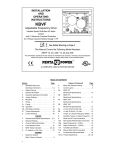
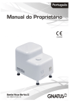
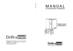
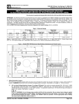
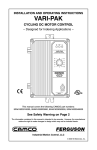
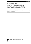
Chapter
m
71
7
Maintenance
Introduction to Maintenance Procedures
The Series One and Series One Plus PCs are designed to provide trouble-free operation. However,
occasionally situations requiring corrective action do occur and it is important to be able to quickly
identify the source of such situations and correct them. Many times the need for corrective action
originates outside of the PC.
Troubleshooting Aids
.-
The advantages provided by the Series One and Series One Plus PC design are indicators and built-in
aids to troubleshooting not only the PC, but also the overall control system. The main diagnostic tool is
the programmer that can be easily attached to the PC. The programmer provides great insight to the
status of the overall control system. When troubleshooting a Series One or Series One Plus PC based
control system, make a habit of having a programmer with you.
Basic Troubleshooting Procedure
The following questions should be asked and appropriate action taken to negative answers. At the end
of the list of questions are step by step procedures to be followed to replace various modules in a Series
One or Series One Plus PC. All major corrective action can be accomplished by replacing modules.
No special hand tools are required except for a screw driver and voltmeter. There is no requirement for
an oscilloscope, highly accurate voltage measurements (digital voltmeters), or specialized test programs. Refer to figure 7.1 for location of the rckmnced indicators.
1. Is PWR (Power) light ON? If not, measure power at the input voltage terminals (98-126 V ac or
195-252 V 8~ as appropriate) on racks using an AC source of power. For racks rquiring a DC
power source, measure the DC voltage between the +24 and 0 V terminals. If the appropriate AC
or DC power is not present, locate the source of the problem external to Series One or Series One
Plus PC. If the AC or DC power levels are correct but the PWR light is off, fuses should be
checked, then rcpl acement of the CPU rack if necessary.
2 . Is CPU light OFF? If ON, check which error code is displayed, r&r to table 4.1 for error code
.
action.
d&nitions and take F
3 . IS RUN light ON? If not, check for the cause such as the programmer in the PRG or LOAD
position or programming errors. If RUN light is OFF and a pgrammcr is not mnnwtcd, or the
propammcrinintkRUNmodcwith
ou t an error code being displayed, rcp&0c the CPU module.
4 Is the BAT’I’ light ON? If yes, replace the battery. Sin= the BATI’ light 5s only a warning level,
the program my be unaltered even if the batt#y is low. Afk replacing the brm#y, examine the
programoYtcstthOc
apcrati01~ Ifafaultislocatedreloadtheprogramfnrmtapencordedattht
completion of initial system programming.
l
5.
Inmultiple~syaemsifthecPUisoperating,~RuNrelaycanbe~~~fulin~wifying
operation of the other pz.;a* supplies. If the RUN relay is not closed @igh resistance) check the
AC or DC poww impply as in step 1 above. Adequate AC or DC power and 8n open relay requires
replacement of the rack.
m
72
Maintenance
GmMo842
a40288
Figure 7-l. Troubleshooting Indicators
General Troublesbooting Procedure
Additional procedures depend upon knowledge of the
are more general in nature and should be modified
application. There 8l[r$no better troubleshooting tools
the programmer and place it in the RUN mode, then
logic installed by the user. ‘I3e following stqx
or adjusted as necessary to meet your specific
than common sense and experience. First plug in
follow these steps:
1. If the Series One or Series One Plus PC has stopped with some outputs energized or basically in
mid-stream, locate the signal (input, timer, coil, sequencer, etc.) that should cause the next operation
to occur, The programmer will display ON or OFF condition of that signal.
2 . If the signal is an input, compare the programmer state with the LED on the input module. If they
are Merent, replace the input module. If multiple modules in an expansion rack appear to require
replacement, ver@ the I/O cable and its connection before replacing any modules.
3 . If input state and LED on the input module agree, compare the LED status and the input device
(pushbutton, limit switch, etc.). If they are different, measure the voltage at the input module (refer
to Chapter 6 for typical I/O wiring). If the voltage indicates a problem, replace the I/O device, field
wiring, or power source; otbwisc; +ace the input module.
4 . Ifthesignalisacoilwindtoafield~vice,campareitsmatustothe
LEDontheoutputmodule.
If
they arc difSercnt, verify the source of field power to ensure exitation voltage is available. If field
power is not present, examine the power source and its wiring. If tbc pqxr Geld power is
available, but the status is wrong af the W module’s output fenninal, repke tht output module or
vcri@thattherackisprovidingthcproperpowcrtotbemodule.
5.
IfthesignslisaooilandeitherthereisM,outputmoduleortheou~ut
is~~8Hhecoilstate,
examinethelogicdrivingtheoutputwithtbeprognrmmerandahardcopyoftheprogram.
proceeding fhm tight towards
le& locate first contact that is not passing power that is otherwise
.
availabletoitfkomW
left. Troubleshootthatsignalperstcps2and
3aboveifitisan
input, or 4 4 5 if it is a coil. EnSVnr:&.S Master Control Relays arc not tikting operation of the
logic.
m
73
Maintenance
6. If the signal is a timer that has stopped at a value below 9999, other &MIIoooo, replace the CPU
module.
7. If the signal is the control over a counter, examine the logic controlling
count signal. Follow steps 2 through S above.
the reset first and then the
Replacement of Components
The following proceduzs provide details on proctdms
Series One or Series One Plus PC system.
to be followed when replacing components of a
Replacing a Rack
1. Tum OFF power and reTnove the programmer (if installed).
2 . Remove the plastic cover and disconnect power wiring from the terminal board on the lower right
side of the rack.
.-
3 . Remove all I/O modules. YO wiring does not have to be disturbed if setice
during
the original
installation.
loop was provided
of each module in the rack for proper
Note the position
reinstallation.
4 . Remove CPU module (if installed) and any filler modules.
Place them aside in a safe location for
later reinstallaxion.
S. Remove bottom two bolts holding the rack in place.
Loosen but do not remove the top bolts.
6 . Slide base unit up and then pull forward to clear the top mounting
bolts. Set the rack aside.
7 . Reinstall the new rack onto the top mounting bolts.
8 . Insert bottom bolts and tighten all four mounting bolts.
9 . Install the m
Placinga module
modules in the same slots from which they were removed.
in the
wrong
slot m cause incorrect and dangerous operation of the control system.
10. Install the CPU and any filler modules that were removed.
11. Reconnect power wiring to the terminals on the right
side of the rack. Reinstall the plastic cover
over the power terminals.
check aperation of the entire
12* Verify proper power wiring and then tum power ON. Carely
~~toenrmrethatall~modulesartinthcirpraperlocationsand~programisnotaltertd.
Replacing a CPU Module
1 Turn OFF power and move
l
2 . S+=z
the programmer (if installed).
the CPU nmdule ait the front, top and bottom to rtleast securing t&s.
3 Pull the module tight
l
4 a If PROM mmv
out dram its slot.
had been installed in the CPU, szmove the PROM and &tall
& h &e new CPU.
Maintenance
GEL90842
5 . Insert the new CPU module by f’irstaligning the printed circuit boards into the bottom board guide.
6 Rotate the module upwards slightly to engage the top board guide.
l
7 . Push the CPU module into the rack until both tabs snap into place.
8 . Reinstall the programmer and reapply power.
9 . Reload the program from tape recorded after initial system programming. Check operation of entire
system.
Replacing l/O Modules
1. Tum OFF power from both the rack and the UO system.
2 . Remove the plastic cover from over the temkals
on the I/O module to be replaced.
wiring on the defective module needs to be removed.
*-
Only field
3 . Disconnect field wiring from I/O teminals, detach the removable connector, or remove the connector to the I/O Interface cable, as applicable according to the type of module. Lzibel each wire or
nott installed wire marking for future reconnection.
4 . Squeezethe I/O module at the fkont, top and bottom to release securing
tabs.
5 . Pull the I/O module straight out.
6 . Insert the new I/O module, aligning printed circuit boards fint into the bottom board guide.
7
l
Rotate the module slightly upwards to engage the top board guide.
8 . Push the module into the rack until both tabs snap into place.
9. Reconnectall field wiring, replace the removable
connector board or n=pplace the connector,
then
xcplace the plastic cover.
10. Reapply power to the CPU, then to the I/O system. Check operation of the system, especially the
UO module that was replaced.
Replacing the Battery
If the CMOS memory back-up battery requires replacement, s&r to the following procedures. Figure
7.2 shows the battery location on the CPU, location of the battery connector and the bmry tie-down
=4=
75
Maintenance
m
a40289
Figure 7-2. Battery Location and Connection
.-
1. Remove the CPU following the previous instructions.
2 . Cut the plastic tie down straps that secure the battery to the board.
3 Disconnect the battery. There is sufficient capacitance in the system to retain the CMOS memory
contents even without the battery for about 20 minutes.
l
I
WARNING
I
The lithium battery sbould be handled with care. DO NOT discard tbe battery iu fire. DO
NOT attempt to recharge the battery. DO NOT short the battery. If these precautions are
not followed, the battery may burst, bum or release hazardous materials.
4 . Connect the new battery (catalog no. IC610ACC150)
and place it in its proper position on the
printed circuit board.
5 . Secure with new tie downs or insulated wire.
6 . Reinstall the CPU module.
7 . Verify that the BATI’ light is OFF.
If necessary, reload the CPU from a tape m&e afkr initial
system pro gramming. Then, check operation of the entire system.
8 . Iftht~oprintedcircuitboardsthatmakeupthtcPUarcseparated,ensuItthattheyare
~~onnccted, installed in a rack, and power4 up. Otherwise, logic may lock into a high current
drainmodeandp remauely drain the battezy.
Adding Memory
The following procedure should be followed when adding memory to a Series One 0~ Series One Plus
PC. Either CMOS IUiM memory can be added to increase mory
capacity fnnn 700 words to 1724
words or non-volatile PROM memory can be installed that contaim a pmgmm previously entered into
the PROM.
76
Maintenance
I,
a40290
Figure T3. Location of Extra Memory Socket
.-
1. Before installing additional memory, it is recommended that any prow
currently in memory be
horded
on tape. If this is not done, the program will be lost after memory is added and a Clear All
Memory operation
is performed.
2 . Remove the CPU following previous instructions.
3 . hate
spare memory socket at the rear of the larger printed circuit board
in the CPU.
4 . Obtain the required memory IC either type 6116LP for Series One or 6264LP-15 for a Series One
Plus, 2K x 8 bit CMOS RAM: (or equivalent).
If adding PROM memory, obtain an Intel type
2732A-2 for Series One or a 27256-25 for a Series One Plus (or equivalent PROMS). Ensure that
the CMOS RAM or PROM is correct for your PC.
When handling CMOS memory 10, aiways handle by the case and not leads. Static
electricity on leads can damage internal circuits, This damage may not be apparent for
several days or weeks of operation.
5 . Orient the IC so that the notch at one end matches the notch in the memory
socket.
6 . For clearance when insMing memory ICs, it may be necessary to lift the smaller printed circuit
board l/8” (3mm). Do not separate the boards. After the mcmoxy IC is instab& reseat the smaller
‘board,
1 . Insert the IC intothe socket casefblly and evenly so as not to bend any leads. Visually inspect to
cnsurethatallleadsateinplaceandthenpushdowntofirmlyscattheIC.
Ifa6assary,rcadjustthe
jumpers and/or switch 2 as shown in table 3.2.
8 . IfthetwoprintedcircuitboardsthatmakeuptheCPUarescparated
ensurethattheyare
reconnect& installed in a base unit, and powed up. Othcwisc, logic may lock into a high cuxzent
&ainmodeanciprcuWwelydrain
thebaitte~.
9 . Reinstall the CPU module following pwious
instructions.
Maintenance
10. Power-up the CPU, place the mode switch in the PRG position and perform a Clear All Memory
operation (CLRSHF348DE~.
The entire memory will now be entirely clear of data. Any
pqram
previously recorded on tape can now be loaded into the CPU from tqe or a new program
can be entered.
Spare Parts and Components
To support the Series One or Series One Plus PC, an Accessory Kit is available (ICalOACC120). This
kit includes commonly needed components that may get damaged or lost in the normal course of
operation. For a complete list of accessories for the Series One Family of programmable controllers,
refer to GEP-762. Rather than axtempting to place ord?rs for plastic covers, fuses, audio cables, screws,
etc., this kit can be ordered and provides sufficient material to support 3-5 CPUs depending upon their
I/O count. Included in the kit arxzthe following items:
I
ITEM
ITEM
QW@
Cable, Frogrammer to Tape Rccder
Cable, Programmer to Peripheral
1
1
cover,cPucoM!eaor
1
Cover (large), DCU, PROM Writer,
Rinter Interface
Cover (small), DCXJ, PROM Writer,
Printer Interface
Cover, I/O Termid
Cover, Power Supply Terminal
Cover, Rack Dust
Fuses, 1A SB
Fuses, 2A SB
2
Fuses, 2A SB (Spiral Ekmcnt)
Fuses, 3A FB
Fuses,3A
SB
Rises, 4A SB
Fuses, SA FB
Fuses, 1OA SB
Key, Hand-Held Programmer
Screws, PH (M3x5)
Screws, PH @43x7)
Screws, PH @43x16)
Spacer
1
4
2
1
5
3
QW*
3
5
5
3
3
5
1
10
10
10
3
When supporting a Series One or Series One Plus installation, it is recommended that spare modules be
available on site. These are in addition to the Accessory Kit previously discussed. As a guide to your
requirements, the following percentages are presented. As a minimum, one each of all modules is
recommended. Depending upon a number of application related conditions (location, average weekly
hours of qxration, cost of downtime, etc.) more units may be justified.
I
Base with Power Sqply
CPLJS
Inpat
b!bdn@
outplt
~~
Rw==-
(=b
Cd
cables
Puipbual Devias
type)
type)
96 SPARES
15
15
10
1s
10
10
10
Maintenance
GEIC-90842
a40022
Figure 74. Accessory Kit for Series One/One Plus
Fuse
List
Table 7.1 is a list of fuses used in Series One I/O modules.
Table 7-l. I/O Module Fuse List
I/O MODULE
CATALOG
NUMBER
CURRENT
RATING (AMPS)
CIRCUIT
CONNECTION
QU-
TYPE OF FUSE
IC61OMDL103
ICdlOMDLlO4
IC61OMDLllS
3 Amps
10 Amps
3 Amps
1
1
2
sokieIed
-clip
fuseclips
picofb
miniame sb
rninhm sb
IC61OMDLlSl
IC61OMDL153
lC61OMDLl54
3 Amps
5 Amps
.5 Amps
2
4
4
sokkzed
filseclips
filscclips
pica
SIiniahlrefb
miniahuefb
IC61OMDL155
IC6lOMDL156
IC6lOMDL157
3 Amps
3 Amps
3Amps
5 Amps
5-s
3Amps
10 Amps
5Amps
2 Amps
5 Amps
2
4
2
sol&d
Soldered
pi=)
pim
SddCred
tic0
2
2
4
2
1
2
sol&led
soldered
pi=
pico!b
lxkimrefb
miniature sb
nkiame sb
IC6lOMDL158
IC61OMDLl75
IC61OMDL176
Ic61oMDLl8o
IC61OMDLl81
mslOMDLl82
IC61OhJDLl85
2
f=clips
fuscclips
fuse clip
fiase dip
sohked
NW