1
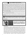
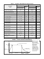
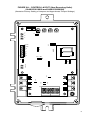
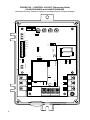
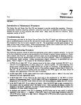
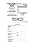
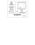
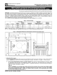
INSTALLATION AND OPERATING INSTRUCTIONS
VARI-PAK
CYCLING DC MOTOR CONTROL
– Designed for Indexing Applications –
ON
STOP
OL
VARI-PAK
DC MOTOR SPEED CONTROL
40
50
60
70
30
20
80
10
90
0
100
%
144 S. Wolf Rd
Wheeling, IL 60090
(847) 459-5200
RUN
JOG / STOP
NEMA-12
This manual covers the following CAMCO part numbers:
92A61633010000, 92A61633020000, 92A61633030000, 92A61633040000
See Safety Warning on Page 2
The information contained in this manual is intended to be accurate. However, the manufacturer
retains the right to make changes in design which may not be included herein.
Industrial Motion Control, LLC
© 2003 KB Electronics, Inc.
TABLE OF CONTENTS
Section
Page
i.
Simplified Operating Instructions . . . . . . . . . . . . . . . . . . . . . . . . . . . . . . . . . . . . . . . . . . 1
ii.
Safety Warning . . . . . . . . . . . . . . . . . . . . . . . . . . . . . . . . . . . . . . . . . . . . . . . . . . . . . . . 2
I.
Introduction . . . . . . . . . . . . . . . . . . . . . . . . . . . . . . . . . . . . . . . . . . . . . . . . . . . . . . . . . . 2
II.
Mounting . . . . . . . . . . . . . . . . . . . . . . . . . . . . . . . . . . . . . . . . . . . . . . . . . . . . . . . . . . . . 8
III.
Setting Motor Current (Jumper J1) . . . . . . . . . . . . . . . . . . . . . . . . . . . . . . . . . . . . . . . . . 8
IV. Wiring . . . . . . . . . . . . . . . . . . . . . . . . . . . . . . . . . . . . . . . . . . . . . . . . . . . . . . . . . . . . . . 8
V.
Fusing . . . . . . . . . . . . . . . . . . . . . . . . . . . . . . . . . . . . . . . . . . . . . . . . . . . . . . . . . . . .
10
VI. Logic Function and Wiring . . . . . . . . . . . . . . . . . . . . . . . . . . . . . . . . . . . . . . . . . . . . . . 10
VII. Application Wiring Diagrams . . . . . . . . . . . . . . . . . . . . . . . . . . . . . . . . . . . . . . . . . . . . . 12
VIII. Application Wiring Diagrams (Reversible Models) . . . . . . . . . . . . . . . . . . . . . . . . . . . . . 15
IX. Operation . . . . . . . . . . . . . . . . . . . . . . . . . . . . . . . . . . . . . . . . . . . . . . . . . . . . . . . . . . . 15
X.
Trimpot Adjustments . . . . . . . . . . . . . . . . . . . . . . . . . . . . . . . . . . . . . . . . . . . . . . . . . . . 16
XI. Function Indicator Lamps . . . . . . . . . . . . . . . . . . . . . . . . . . . . . . . . . . . . . . . . . . . . . . . 17
XII. Troubleshooting Guide . . . . . . . . . . . . . . . . . . . . . . . . . . . . . . . . . . . . . . . . . . . . . . . . . 19
Tables
1.
Electrical Ratings . . . . . . . . . . . . . . . . . . . . . . . . . . . . . . . . . . . . . . . . . . . . . . . . . . . . . . 3
2.
General Performance Specifications . . . . . . . . . . . . . . . . . . . . . . . . . . . . . . . . . . . . . . . . 4
3.
Selectable Jumper Reference Chart . . . . . . . . . . . . . . . . . . . . . . . . . . . . . . . . . . . . . . . . 8
4.
Jumper J1 Setting vs Motor Horsepower . . . . . . . . . . . . . . . . . . . . . . . . . . . . . . . . . . . . 8
5.
Terminal Block Wiring Information . . . . . . . . . . . . . . . . . . . . . . . . . . . . . . . . . . . . . . . . . 9
6.
Jumper “JW” Operation . . . . . . . . . . . . . . . . . . . . . . . . . . . . . . . . . . . . . . . . . . . . . . . . 12
Figures
1.
Typical Indexing Performance . . . . . . . . . . . . . . . . . . . . . . . . . . . . . . . . . . . . . . . . . . . . 4
2A. Control Layout (Non-Reversing Units) . . . . . . . . . . . . . . . . . . . . . . . . . . . . . . . . . . . . . . 5
2B. Control Layout (Reversing Units) . . . . . . . . . . . . . . . . . . . . . . . . . . . . . . . . . . . . . . . . . . 6
3.
Mechanical Specifications . . . . . . . . . . . . . . . . . . . . . . . . . . . . . . . . . . . . . . . . . . . . . . . 7
4.
AC Line & Armature Connection . . . . . . . . . . . . . . . . . . . . . . . . . . . . . . . . . . . . . . . . . . . 9
5.
Remote Potentiometer Connection . . . . . . . . . . . . . . . . . . . . . . . . . . . . . . . . . . . . . . . . 10
6.
Analog Voltage Connection . . . . . . . . . . . . . . . . . . . . . . . . . . . . . . . . . . . . . . . . . . . . . 10
7.
Run Command . . . . . . . . . . . . . . . . . . . . . . . . . . . . . . . . . . . . . . . . . . . . . . . . . . . . . . . 10
8.
Jog Command . . . . . . . . . . . . . . . . . . . . . . . . . . . . . . . . . . . . . . . . . . . . . . . . . . . . . . . 11
9.
Jog Command used as Stop . . . . . . . . . . . . . . . . . . . . . . . . . . . . . . . . . . . . . . . . . . . . . 11
10. Stop Command . . . . . . . . . . . . . . . . . . . . . . . . . . . . . . . . . . . . . . . . . . . . . . . . . . . . . . 11
11. Jumper “JR” Operation . . . . . . . . . . . . . . . . . . . . . . . . . . . . . . . . . . . . . . . . . . . . . . . . . 12
12. Solid State Switching . . . . . . . . . . . . . . . . . . . . . . . . . . . . . . . . . . . . . . . . . . . . . . . . . . 13
13. Contact Switching . . . . . . . . . . . . . . . . . . . . . . . . . . . . . . . . . . . . . . . . . . . . . . . . . . . . 13
14. Correct Keyway Position for CAM & Limit Switch Assemblies . . . . . . . . . . . . . . . . . 13, 14
15. Cycle on Demand Wiring . . . . . . . . . . . . . . . . . . . . . . . . . . . . . . . . . . . . . . . . . . . . . . . 14
16. Sequence of Cycle on Demand Operation . . . . . . . . . . . . . . . . . . . . . . . . . . . . . . . . . . 15
17. Reversing Logic Wiring Diagram . . . . . . . . . . . . . . . . . . . . . . . . . . . . . . . . . . . . . . . . . 16
18. Internal Wiring Diagram . . . . . . . . . . . . . . . . . . . . . . . . . . . . . . . . . . . . . . . . . . . . . . . . 20
ii
i.
SIMPLIFIED OPERATING INSTRUCTIONS
IMPORTANT – You must read these simplified operating instructions before proceeding. These instructions are to be used as a reference only and are not intended
to replace the detailed instructions provided herein. You must read the Safety
Warning, on page 2, before proceeding.
A1
A. AC Power – Use 120
Volt AC rated controls on
120 Volts AC and 240
Volt AC rated controls on
240 Volts AC. Connect
AC power to terminal
block TB2 terminals L1
and L2. When power is
applied, the power on
(ON) LED on the front
cover will illuminate.
TB2
A1
A2
L1
L2
M
AC LINE
INPUT
MOTOR
Be sure input AC line
voltage corresponds to
control voltage rating. Be sure
AC power is disconnected
when making other connections to control. Do not
bundle AC power and motor
wires with wires connected to
TB1 terminals.
B. Motor Leads – Connect the
motor leads to terminal block TB2
terminals A1 and A2. Be sure
motor nameplate voltage rating
corresponds to control output voltage rating. Do not use control
with shunt wound motors.
Do not connect
ground wire to any
other terminal
Earth
Ground
JUMPER J1 SETTING vs
MOTOR HORSEPOWER
Motor Horsepower Range
Jumper J1
90 VDC
2A
3.3A
5A
10A
180 VDC
1/6
1/3
1/4 – 1/3
1/2 – 3/4
1/2
1
3/4 – 1
11⁄2 – 2
Note: Jumper “J1” is shown in the factory setting for
120 Volts AC controls (3.3 Amps).
C. Motor Current Setting – Be sure Jumper J1 is set to the approximate rated motor
current (10A, 5A, 3.3A, 2A).
D. Trimpot Settings – Trimpots should be set to the approximate position as shown:
MIN
MAX
CL
IR
E. Main Speed Pot – Turn the main speed pot on the front cover of the control to a 15%
or greater setting.
Special Instruction for Cycle on Demand Applications
The camshaft of the Index Drive should be in the middle of its dwell position. This is the position in which the motor should receive its signal to start. Connect the normally closed side
of the cycling limit switch (LS1) to the control’s TB1 terminals STOP (4) and RTN (3). Note:
See figure 14A-C, on pages 13 and 14, for information regarding the correct dwell
position for your Index Drive model and cycling cam lobe positions.
1
ii.
!
SAFETY WARNING! Please read carefully
This product should be installed and serviced by a qualified technician, electrician, or electrical maintenance person familiar with its operation and the hazards involved. Proper installation, which includes wiring, mounting in proper enclosure, fusing or other over current protection, and grounding can reduce the chance of electrical shocks, fires, or explosion in this
product or products used with this product, such as electric motors, switches, coils, solenoids,
and/or relays. Eye protection must be worn and insulated adjustment tools must be used
when working with control under power. This product is constructed of materials (plastics,
metals, carbon, silicon, etc.) which may be a potential hazard. Proper shielding, grounding
and filtering of this product can reduce the emission of radio frequency interference (RFI)
which may adversely affect sensitive electronic equipment. If further information is required
on this product, contact the Sales Department. It is the responsibility of the equipment manufacturer and individual installer to supply this Safety Warning to the ultimate end user of this
product. (SW effective 9/2000).
This control contains Start/Stop and Inhibit circuits that can be used to start and stop the
control. However, these circuits are never to be used as safety disconnects since they are not
fail-safe. Use only the AC line for this purpose.
The potentiometer circuit (P1, P2, P3) of this control is not isolated from AC line. Be sure
to follow all instructions carefully. Fire and/or electrocution can result due to improper use of
this product.
This product complies with all CE directives pertinent at the time of manufacture.
Contact factory for detailed installation and Declaration of Conformity. Installation of a
CE approved RFI filter (KBRF-200A [P/N 9945C] or equivalent) is required. Additional shielded motor cable and/or AC line cables may be required along with a signal isolator (Camco P/N
99A61455000000).
A label like the one shown, appears on
the top side of your VARI-PAK unit. If
this label is not on your control, notify
CAMCO immediately! 1-800-645-5207.
I.
2
INTRODUCTION
The VARI–PAK Series is housed in a rugged die cast aluminum NEMA 12 enclosure. The
controls are designed specifically for cycling and indexing applications. A variety of models
provide different features and input voltage ratings (see table 1, on page 3). The controls provide the user with isolated logic functions: STOP, JOG and RUN. Other functions, such as
cycle on demand, can easily be obtained. An important feature of the control is jumper J1
which is used for DC current selection. It automatically presets the IR Compensation and
Current Limit for safe operation on various motors. Standard features include an LED indicator array for “power on,” “stop” and “overload.” Part Numbers 92A61633020000 and
92A61633040000 also contain logic input for “Reverse Run” and “Reverse Jog.” The controls contain trimpots that can be used to readjust Minimum and Maximum speed, Current
Limit and IR Compensation. The front panel contains a built-in 5K ohm speed potentiometer
and a Run, Jog/Stop switch. (See table 3, on page 8, for selectable jumper information.)
3
0 – 90
120
120
240
240
92A61633010000
92A61633020000
92A61633030000
92A61633040000
0 – 180
0 – 180
0 – 90
Motor Armature
Voltage (VDC)
Input Line Voltage
(VAC 50/60 Hz ± 10%)
Part Number
15.0
15.0
15.0
15.0
Maximum AC
Load Current
(RMS Amps)
10.2
10.2
10.2
10.2
Maximum DC
Load Current
(DC Amps)
TABLE 1 – ELECTRICAL RATINGS
2, (1.5)
2, (1.5)
1, (0.75)
1, (0.75)
Maximum
Horsepower
HP, (kW)
Reversing
Unidirectional
Reversing
Unidirectional
Type of
Operation
Fwd Run, Fwd Jog,
Stop, Rev Run, Rev
Jog, Rtn
Run, Jog, Stop, Rtn
Fwd Run, Fwd Jog,
Stop, Rev Run, Rev
Jog, Rtn
Run, Jog, Stop, Rtn
Logic Provided
IMPORTANT! Control part number and ratings must correspond to the AC line voltage, motor voltage and type of operation (Unidirectional or Reversing). See table 1.
TABLE 2 – GENERAL PERFORMANCE SPECIFICATIONS
Specifications
Specifications
Part Nos.
Parameter
(Units)
Part Nos.
Factory
Setting
92A61633010000
92A61633020000
AC Line Input
(VAC ± 10%, 50/60 Hz)
Horsepower Range HP, (kW)
92A61633030000
92A61633040000
Factory
Setting
115
—
208/230
—
1/6 – 1, (0.12 – 0.75)
1/3, (0.25)
1/3 – 2, (0.25 – 1.5)
1/4, (0.18)
0 – 100
85
0 – 200
170
Armature Voltage Range (VDC)
Current Ranges (ADC)
2, 3.3, 5, 10
3.3
2, 3.3, 5, 10
2
CL Trimpot Range
(% Range Setting)
0 – 170
150
0 – 170
150
MIN Speed Trimpot Range
(% Base Speed)
0 – 30
0
0 – 30
0
MAX Speed Trimpot Range
(% Base Speed)
60 – 120
100
60 – 120
100
0 – 15
4
0 – 30
8
IR COMP Trimpot Range
(% Base Speed)
Speed Range (Ratio)
50:1
—
50:1
—
AC Line Voltage Regulation
(% Base Speed)
± 0.5
—
± 0.5
—
Voltage Following Linearity
(% Base Speed)
± 0.5
—
± 0.5
—
±1
—
±1
—
0 – 45
—
0 – 45
—
5K – 1/3
—
5K – 1/3
—
Maximum Run/Stop Operations
(ops/min)
30
—
30
—
Enclosure Type (NEMA)
12
—
12
—
Load Regulation
(% Base Speed)
Ambient Temperature Range (ºC)
Potentiometer, Front Cover
(ohms – watts)
FIGURE 1 – TYPICAL INDEXING PERFORMANCE
SPEED
(rpm)
MOTOR BASE RATED SPEED
1800
DECEL WITH
DYNAMIC BRAKE
FIXED
ACCEL
100
4
TIME (msec)
250
Maximum Cycle
Rate: 30 cycles
per minute with
typical 1 HP motor.
Total reflected
inertia not to
exceed 20% of
armature inertia.
Acceleration time
(fixed at 0.1 sec.)
may be extended
when operating in
Current LImit
FIGURE 2A – CONTROL LAYOUT (Non-Reversing Units)
(92A61633010000 and 92A61633030000)
(Illustrates Factory Setting of Jumpers and Approximate Trimpot Settings)
MIN
CL
IR
CON2
R
S
JW
J1
KBPI
NC NO
JS
90V 180V
J3
JR
F
TB1
RUN FWD
(6)
JOG FWD
(5)
STOP
(4)
RTN
(3)
+24V
(2)
COM
(1)
2A
3.3A
5A
10A
P1
P2
P3
CON1
MAX
O
240V
120V
RB1
J2B
J2A
A1B
A2B
A2A
A1A
RB2
P4
TB2
A1
A2
L1
L2
5
FIGURE 2B – CONTROL LAYOUT (Reversing Units)
(92A61633020000 and 92A61633040000)
(Illustrates Factory Setting of Jumpers and Approximate Trimpot Settings)
MIN
CL
IR
CON2
P3
CON1
MAX
R
S
J1
KBPI
NC NO
JS
90V 180V
240V
P1
F
J3
RB2
RB1
KBPI RELAY
O
JR
TB1
RUN REV
(8)
JOG REV
(7)
RUN FWD
(6)
JOG FWD
(5)
STOP
(4)
RTN
(3)
+24V
(2)
COM
(1)
2A
3.3A
5A
10A
P1
P2
JW
120V
240V
J1
A2B
A1B
A2A
A1A
TB2
A1
6
A2
L1
L2
120V
J2B
J2A
8.226
[208.94]
8.876
[225.45]
9.488
[241.00]
0.357
[9.07]
OL
100
NEMA-12
JOG / STOP
RUN
144 S. Wolf Rd
Wheeling, IL 60090
(847) 459-5200
%
10
0
80
90
20
60
70
50
30
40
DC MOTOR SPEED CONTROL
VARI-PAK
STOP
5.000
[127.00]
5.472
[138.99]
ON
RECOMMENDED MOUNTING SCREW: 1/4" (M6)
5.886
[149.50]
FIGURE 3 – MECHANICAL SPECIFICATIONS (Inches / [mm])
7
TABLE 3 – SELECTABLE JUMPER REFERENCE CHART
Jumper
Location*
Description
Factory Setting
J1
1
Establishes the range of maximum armature current
See section III, page 8
J2A, J2B
1
Sets the AC input line voltage (120 or 240 Volts AC) for
the main PC Board
Set according to model part
numbers. See table 1, Page 3
J3
1
Sets the DC output voltage range to motor (90V/180V)
Set according to model part
numbers. See table 1, Page 3
JR
1
Used to activate the return (RTN) circuit. “F” position –
RTN is jumpered to common.
“O” position – RTN used as a logic disable.
See section VI D, on page 11
Set to “F” position
JS
1
Used to set the STOP function operation. “NC” position –
Use a normally closed contact for open to stop operation.
Set to “NC” position
“NO” position – Use a normally open contact for “close to
stop” operation.
J1
2
Sets the operating AC line voltage for the
Relay Board (120 or 240 VAC)
Set according to model part
numbers. See table 1, Page 3
JW
1
Determines the priority of the Run and Stop logic commands. See table 6, on page 12.
Set to “R” position for
“cycle on demand”
*NOTE: Location 1 Main Speed Control Board – Location 2 Relay Board (found on reversing models only).
II.
MOUNTING
Mount the control in a vertical position on a flat surface. Be sure to leave enough room below
the bottom of the control to allow for the AC line and motor connections and other wiring that
may be necessary. Care should be taken to avoid extreme hazardous locations where physical damage can occur. Note: Do not use this control in an explosion proof application.
If the control is mounted in a closed, unventilated cabinet, remember to allow for proper heat
dissipation. If full rating is required, a minimum enclosure size of 12” W x 24” H x 12” D
should be used.
Front Cover – The VARI–PAK case is designed with a hinge so that when the front cover is
open, all wiring stays intact. To open the cover, the four cover screws must be loosened, so they
no longer are engaged in the case bottom. After mounting and wiring, close the front cover,
making sure all wires are contained within the enclosure and the gasket is in place
around the cover lip. Tighten all four cover screws so that the gasket is slightly compressed.
Do not overtighten.
III. SETTING MOTOR CURRENT (Jumper J1)
TABLE 4 – JUMPER J1 SETTING vs
MOTOR HORSEPOWER
Jumper J1 (on the Main Board) is used to
set the range of armature current which
Motor Horsepower Range
Jumper J1
can be further modified with the current
90 VDC
180 VDC
limit (CL) trimpot. The factory setting of J1
1/6
1/3
is 3.3 amps for 120 VAC controls and 2
2A
amps for 240 VAC controls. The CL trim1/4
–
1/3
1/2
– 3/4
3.3A
pot is factory set to provide 150% of the J1
1/2
1
5A
setting. For example, when J1 is in the 10
10A
amp position, the actual armature current
3/4 – 1
1⁄ –2
is 15 amps. When J1 is in the 5 amp position, the control provides a maximum
armature current of 7.5 amps. The position of J1 should be set to the approximate DC motor
current rating. Table 4 is provided as a reference.
1
2
IV. WIRING
WARNING! Read Safety Warning on page 2 before attempting to use this control.
Wire control in accordance with the National Electrical Code requirements and
other codes that apply. Be sure to fuse each conductor which is not at ground potential.
!
8
Failure to follow the Safety Warning Instructions may result in electric shock, fire or explosion.
Do not fuse neutral or grounded conductors. Note: See section V, Fusing, on page 10. A
separate AC line switch, or contactor, must be wired as a disconnect switch, so that the contacts
open each ungrounded conductor. (See figure 4, below for AC Line and Armature Connection.)
Note: Do not bundle AC or motor leads with logic leads or erratic operation may occur.
TABLE 5 – TERMINAL BLOCK WIRING INFORMATION
Terminal Block
Designation
Supply Wire Gauge*
Connection
Designation
Minimum
Maximum
Maximum
Tightening Torque (in-lbs)
TB2
A1, A2, L1, L2
22
12
12
TB1
Logic Connections
24
14
3.5
*Use Cu wire only (AWG)
1. Twist logic wires (speed adjustment potentiometer or voltage signal input wires) to avoid
picking up electrical noise. If wires are longer than 18”, use shielded cable.
2. You may have to earth ground the shielded cable. If noise is coming from devices other
than the drive, ground the shield at the drive end (ground screw in enclosure). If noise is
generated by a device on the drive, ground the shield at the end away from the drive. Do
not ground both ends of the shield.
3. Do not bundle logic wires with power carrying lines or sources of electrical noise. Never
run speed adjustment potentiometer or voltage signal input wires in the same conduit as
motor or AC line voltage wires.
4. Connect earth ground to the earth ground screw provided in the enclosure. (See figure
4 for ground screw location.)
Two .875” (22.2 mm) knockout holes are provided for a standard 1/2” knockout connector (not supplied) for wiring. A plug is provided if only one knockout is required. Be sure
to use suitable connectors and wiring that is appropriate for the application.
FIGURE 4 – AC LINE & ARMATURE CONNECTION
A1
A. AC Line – Connect AC Line to terminals L1 and L2. (Be sure the
control model and rating match
the AC line input voltage. See
table 1, on page 3.)
TB2
B. Motor Armature – Connect motor
armature to terminals A1 (+) and
A2 (-). (See table 1, on page 3).
A1
A2
L1
L2
WARNING! Do not wire switches
or relays in series with the armaEarth
M
Ground
ture. Armature switching can
Do not connect
AC LINE
cause catastrophic failure of
ground wire to any
INPUT
other terminal
MOTOR
motor and/or control. Do not
bundle AC line and motor wires
with other wires (e.g. potentiometer, analog input, Run, Jog, Stop, etc.) since erratic operation may occur. Do not use this control on shunt wound motors.
C. Ground – Be sure to ground (earth) the control by connecting a ground wire to the Green
Ground Screw located to the right of the terminal block. Do not connect ground wire
to any other terminals on control.
D. Main Potentiometer – The control is supplied with the main potentiometer prewired.
However, the control can also be operated from a remote potentiometer, or from an isolated analog voltage for voltage following. To operate from an external source remove
white, orange and violet potentiometer leads from terminals P1, P2 and P3. The leads
may be taped and left in the control. The potentiometer itself may be removed, if a seal
is used to cover the hole in the front cover. Note: Use shielded cable on all connections to P1, P2, or P3 over 12” (30cm) in length. See section IV, items 1-4.
9
1. Remote Potentiometer. Connect remote
potentiometer wires to terminals P1, P2
and P3, so that the “high” side of the
potentiometer connects to P3, the
“wiper” to P2 and the “low” side to P1.
(See figure 5.)
2. Analog Input. An isolated 0-10VDC
analog voltage can also be used to drive
the control. Note: If an isolated signal
voltage is not available, an optional
signal isolator (Camco P/N
99A61455000000) should be used.
Connect the isolated input voltage to
terminal P2 (positive) and P1 (negative).
(See figure 6.) Adjust the MIN trimpot
clockwise to achieve a 0+ output voltage.
V.
FUSING
AC Line Fusing – Most electrical codes require
that each ungrounded conductor contain fusing.
Separate branch circuit fusing or circuit breaker
may be required. Check all electrical codes that
may apply to the installation. This control does
not contain AC line fuses. A 20 amp rated fuse
or circuit breaker can be used.
FIGURE 5 – REMOTE POTENTIOMETER
CONNECTION
P3
5K
P2
P1
FIGURE 6 – ANALOG VOLTAGE
CONNECTION
USE AN ISOLATED
VOLTAGE SOURCE
+
0-10
VDC
-
P2
P1
Warning! Do not ground (earth)
P1 or P2 connection
VI. LOGIC FUNCTIONS AND WIRING
Warning! Do not use any of the logic functions (STOP, RTN) as an emergency
stop since they are not fail-safe. Use only an AC line (L1, L2) disconnect for that
purpose. To prevent erratic operation, do not bundle logic wiring with AC line and
motor wires. Use shielded cables on logic wiring over 12” (30 cm) in length. See section IV, items 1-4, on page 9.
!
The control contains several logic functions which are described in detail below. All connections are made to terminal block TB1. (See figures 2A and 2B, on pages 5 and 6, for TB1
location.)
A. ”RUN” – Note:
FIGURE 7 – RUN COMMAND
This terminal is
sometimes
RUN JOG STP RTN +24V COM
marked “START”
in older models.
A momentary conTB1
tact closure
between terminals
See section IV,
A NORMALLY CLOSED
“RUN” and “RTN”
items 1-4,
CONTACT MUST BE
latches the control
on page 9
INSTALLED BETWEEN
into a continuous
"RTN" AND "STOP" IN
OPEN
ORDER FOR CONTROL
TO STOP
run mode. To stop
TO START, UNLESS
the control, the
JUMPER "JW" IS IN THE
stop circuit must be
CLOSE
"R" POSITION.
TO START
activated by opening the contact
between the
“STOP” and “RTN” terminals. Note: All momentary closures must be present for
no less than 50 milliseconds and a normally closed (NC) contact must be maintained between the “Stop” and “RTN” terminals in order for the drive to run.
10
B. ”JOG” (Stop) – A maintained contact
closure between terminals “JOG” and
“RTN” will cause the control to run
continuously. This is not a latching
function. The drive will run only as
long as the contact is closed and stop
when it is opened. (See figure 8.)
Application Note:
The “JOG” can also be used as a
normally open (NO) “STOP” command. When the control is started
with the momentary “RUN” command, it can be stopped by
connecting a momentary contact between the “JOG” and the
“RTN” terminals. See figure 9.
(Note: The control can also be
stopped by opening the
“STOP” contact.)
C. ”STOP” — Use a normally
closed (NC) contact between terminals “STOP” and “RTN.” Opening the contact activates the
control’s Dynamic Brake producing a rapid stop. (Note: A normally open (NO) limit switch or
contact can also be used to activate the stop command. To
use a (NO) contact, move
jumper JS to the “NO” position). (See table 3, page 8.)
FIGURE 8 – JOG COMMAND
RUN
JOG
STP
See section IV,
items 1-4,
on page 9
RTN +24V COM
CLOSE CONTACT
TO RUN, OPEN
TO STOP
JOG
FIGURE 9 – JOG COMMAND USED AS STOP
RUN
JOG
STP
See section IV,
items 1-4,
on page 9
STOP
RTN +24V COM
NORMALLY OPEN
CONTACT, CLOSE
TO STOP
START
FIGURE 10 – STOP COMMAND
RUN
JOG
STP
RTN +24V COM
Application Note:
The setting of jumper “JW”
establishes the priority a
“STOP” command has over a
See section IV,
items 1-4,
“RUN” command. If jumper
NORMALLY CLOSED
on page 9
“JW” is placed in position “S,”
CONTACT, OPEN TO
STOP
STOP
the “STOP” command has
priority over the “RUN”. If
the “STOP” is activated
START
(contact open), the control
cannot be started with the
“START” command. If jumper “JW” is in the “R” position (factory setting), the “RUN”
command has priority over the “STOP.” In this mode of operation the control can be
started with the “RUN” command even though the “STOP” is activated. This setting of
jumper JW in the “R” position is used for cycle on demand applications. See table 6,
on page 12, for detailed information of jumper “JW” operation. Warning! Do not use as
safety stop. See Safety Warning on page 2.
D. ”RETURN” (RTN) – When Jumper “JR” is moved to position “O” from the factory setting
“F,” it disables all of the command functions (Run, Jog, Stop, etc.) and causes the control
to stop. To enable these functions, a contact must be placed between the “RTN” and
“COM” terminals.
Warning! Do not use as emergency or safety stop. See Safety Warning on page 2.
See figure 11, on page 12, for jumper “JR” operation. Failure to follow the Safety
Warning Instructions may result in electric shock, fire or explosion.
11
TABLE 6 – JUMPER “JW” OPERATION
Jumper “JW” Setting
Description
Circuit
RUN
S
R
JW
Factory setting
JOG
“Run” has priority
over “Stop.” Control
will run even if stop
contact is open. Use
this setting for “Cycle
on Demand” operation.
STP
Operation
RTN
*
STOP
When start contact is
made, control will run
with stop open. If
stop is closed and
then reopened, control will stop.
START
RUN
S
R
JW
JOG
“Stop” has priority
over “Run.” Control
will run only when
stop contact is
closed.
STP
RTN
*
When start contact is
made, stop contact
must be closed for
control to run.
STOP
START
FIGURE 11 – JUMPER “JR” OPERATION
"F" "O"
"JR"
RTN
COM
Jumper “JR” in “F” position (factory setting)
connects “RTN” to “COM”
"F" "O"
"JR"
RTN
Jumper “JR” in “O” position opens the
“RTN” to “COM” circuit allowing the use of
an external disable contact. This will not
stop the indexer in run mode.
COM
*
OPEN TO
STOP
*See section IV, items 1-4, on page 9.
E. +24 VDC SUPPLY – The +24V terminal provides a nominal1 24 VDC @ 12 mA output for
use with an external load such as one solid-state 3-wire proximity switch.
F. Common “COM” — This terminal is referenced to all logic signals (RUN, JOG, STOP)
through the Return (“RTN”) terminal. The control is factory supplied with jumper “JR” in
the “F” position which connects the “RTN” and “COM” terminals together. Note: Control
will not operate unless jumper “JR” is in the “F” position.
VII. APPLICATION WIRING DIAGRAMS
Example 1: Solid-state switching devices, such as NPN transistors or proximity switches,
may be used for logic commands if they meet the following criteria:
1
Output voltage provided can vary between 20 and 24 Volts DC.
12
Capable of switching 30 VDC, at 24 mA,
with an off-state leakage current of less
than 1 mA. (See figure 12.) Warning!
Do not ground or short +24V to COM or
return on TB1. Do not use +24V for
other than open collector sensors. (See
figure 12.)
Example 2: For optimum operation,
contacts used on logic inputs should be
rated for low-level logic switching (i.e.
gold contacts). (See figure13.)
FIGURE 12 – SOLID STATE SWITCHING
RUN
JOG
See section IV,
items 1-4,
on page 9
STP
RTN +24V COM
+V
STOP
JOG
NOTE: JUMPER
"JR" MUST
BE IN THE
"F" POSITION
Example 3:
“Cycle on Demand” –
START
Important Information
In a “Cycle on Demand” application, the
CAMCO Index Drive will make one comFIGURE 13 – CONTACT SWITCHING
plete cycle of movement of table or conveyor and then dwell until it receives an
RUN JOG STP RTN +24V COM
external signal from the machine’s controller or operator to start again. If motor
receives a signal to start while the CAMCO
Index Drive is in its dwell position, the
motor will accelerate from a paused posi+V
tion to full speed during one half of the
See section IV,
items 1-4,
dwell of the main index cam. When the
on page 9
motor has reached its maximum speed
and is no longer accelerating, the motion of
STOP
RTN
the CAMCO Index Drive can start. As the
NOTE: JUMPER
Indexer re-enters its dwell portion of the
"JR" MUST
main cam, the signal cam located on the
JOG
BE IN THE
camshaft of the CAMCO Index Drive will
"O" POSITION
actuate the limit switch to signal a stop.
START
(Note: Due to time delays, the signal cam
may have to signal a stop some degrees
before the index drive actually enters the dwell.) It is important that the motor is made to stop
while in the dwell of the main cam. Stopping in any other position could damage the control or
the Index Drive! Read all the instructions carefully in order to familiarize yourself with your new
CAMCO Index Drive. (See figures 14A, 14B and 14C.)
FIGURE 14 – CORRECT KEYWAY POSITION FOR CAM & LIMIT SWITCH ASSEMBLIES
FIGURE 14A – ROLLER GEAR UNIT
Keyway
Type II Extra
CAM LOBE
A standard Roller Gear unit
with the CAM & Limit Switch
mounted on the correct keyway position directly opposite
of the output shaft, 90º (clockwise) from the CAM Lobe.
The CAM & Limit Switch may
also be mounted on the
reducer. If the unit has a
“Type II” motion, a special
Limit Switch CAM is needed
with one extra Lobe, 180º
from the first Lobe (as shown).
Note: On some RDM units
(such as the 601 RDM), the
CAM & Limit Switch is
mounted at an angle.
13
FIGURE 14B – RIGHT ANGLE UNIT
FIGURE 14C – PARALLEL UNIT
Keyway
Keyway
A standard right angle unit with the CAM &
Limit Switch mounted on the housing has a
correct keyway position directly opposite of
the CAM Lobe. CAM & Limit Switch may also
be mounted on the reducer.
The “Cycle on Demand” function is
required for most indexing table applications. The control can be easily set for
this operation as follows:
1. Jumper “JW” must be in the “R” position (factory setting) see table 6, on
page 12.
2. Jumper “JR” must be in the “F” position (factory setting) see section VI D,
on page 11.
3. Wire limit switch LS1 (normally closed)
and start switch (normally open) as
shown.
A standard parallel unit with the CAM & Limit
Switch mounted on the housing has a correct
keyway position directly opposite of the output
shaft, 90º (clockwise) from the CAM Lobe. CAM
& Limit Switch may also be mounted on the
reducer.
FIGURE 15 – CYCLE ON DEMAND WIRING
MOMENTARY
START
SWITCH
(N/O)
6
RUN
5
JOG
4
STOP
3
RTN
LS1 (N/C)
See section IV,
items 1-4,
on page 9
2 +24V
The “Cycle on Demand Operation”
begins with limit switch LS1 riding on the
CAM lobe. (Since LS1 is a normally
1 COM
closed switch, it will be open when riding
on the lobe.) The cycle is initiated by
momentarily closing the start switch. The
drive will start even though LS1 is open.
(Jumper JW is in the “R” position giving priority to the start switch which overrides the
stop.) As the camshaft rotates, it moves off LS1 which closes. When the lobe rotates
around back to LS1, LS1 now opens and the drive stops. The drive is now ready to repeat
the cycle by initiating another start command. See figure 16, on page 15.
Note: A normally open (NO) STOP contact can also be used. To convert to a normally open STOP, move jumper JS from the factory position “NC” to position “NO.”
14
FIGURE 16 – SEQUENCE OF CYCLE ON DEMAND OPERATION
LS1
CONTACT IS OPENING
LS1
CONTACT CLOSES
ROTATION
OF CAM
1) CLOSE START BUTTON TO INITIATE
CYCLE (MOMENTARY CLOSURE)
2) CAM ROTATES, LS1 CONTACT CLOSES
LS1
LS1
CONTACT REMAINS
CLOSED
1) CAM CONTINUES TO ROTATE THROUGH
CYCLE, LS1 REMAINS CLOSED
CONTACT OPENS
4) CAM ROTATES UNTIL LOBE UNTIL LS1 CONTACT,
DRIVE BRAKES TO A STOP. CLOSE MOMENTARY
START BUTTON TO INITIATE NEW CYCLE.
VIII. APPLICATION WIRING DIAGRAMS (Reversible Models)
P/N 92A61633020000 (120 VAC) – P/N 92A61633040000 (240 VAC).
Reversing models carry out the same functions as the unidirectional models except they can
be made to index in both the forward and reverse direction. A special circuit APRM® provides a lockout feature that prevents catastrophic damage to the drive if a “Reverse” command is given during “Forward” operation (and vice versa). The reversing drives contain two
additional positions on the terminal block: “Run Rev” and “Jog Rev.” The stop logic command is made with a normally closed (NC) contact.
Note: The sense of the stop logic can be changed from normally closed (NC) to normally open (NO) by placing jumper JS in the “NO” position.
The wiring diagrams on page 16 illustrate typical logic circuits. Many other configurations are
possible. Consult factory if help is needed.
IX. OPERATION
WARNING! Read Safety Warning on page 2 before attempting to operate the
control or severe injury or death can result. Failure to follow the Safety
Warning Instructions may result in electric shock, fire or explosion.
!
15
FIGURE 17 – REVERSING LOGIC WIRING DIAGRAMS
FIGURE 17A – GENERAL
CONNECTION DIAGRAM
FIGURE 17B – REVERSING
USING EXTERNAL CONTACTS
*
8
RUN REV
7
JOG REV
6
RUN FWD
5
JOG FWD
STOP
4
STOP
3
RTN
3
RTN
2
+24V
1
COM
8
RUN REV
7
JOG REV
6
RUN FWD
5
JOG FWD
4
*
JOG
FWD
LS1
FIGURE 17C – CYCLE ON DEMAND
WITH REVERSE
LS2 (N/O)
REVERSE
START
CYCLE
USE NORMALLY OPEN
MAINTAINED CONTACTS
FIGURE 17D – FORWARD AND REVERSE
CYCLE ON DEMAND
*
8
RUN REV
7
JOG REV
6
RUN FWD
5
JOG FWD
*
RUN REV
RUN FWD
8
RUN REV
7
JOG REV
6
RUN FWD
5
JOG FWD
4
STOP
3
RTN
LS2
END OF
CYCLE
STOP REV
4
STOP
STOP FWD
LS1 (N/C)
LS1
3
RTN
*See section IV, items 1-4, on page 9.
After the control has been set up properly (the jumpers set to the desired positions and the
wiring completed), the start-up procedure can begin. If AC power has been properly brought
to the control, the “ON” and the “STOP” indicators will be lighted. Before initially starting, be
sure the main potentiometer is set to approximately 15% rotation. To start the control, move
the Run-Jog/Stop Switch to the “Run” position and release. The “Stop” indicator should extinguish and the motor should rotate as the potentiometer knob is rotated clockwise.
Note: If the motor rotates in the wrong direction, it will be necessary to disconnect the
main AC power and reverse the armature wires. To stop the motor, move the RunJog/Stop Switch to the Stop position. If power is lost the control will not restart,
unless the Run- Jog/Stop Switch is moved to the “Run” position.
X.
16
TRIMPOT ADJUSTMENTS
The control contains trimpots which have been factory adjusted for most applications.
Figures 2A and 2B, on pages 4 and 5, illustrate the location of the trimpots and their approximate adjustment positions. Some applications may require readjustment of the trimpots in
order to tailor the control to exact requirements. (See table 2, on page 4, for range and factory setting of trimpots.) Readjust trimpots as follows:
WARNING! Do not adjust trimpots with main power on if possible. If adjustments are made with power on, insulated adjustment tools must be used and
safety glasses must be worn. High voltage exists in this control. Electrocution and/or
fire can result if caution is not exercised. Safety Warning on page 2 must be read and
understood before proceeding. Failure to follow the Safety Warning Instructions may
result in electric shock, fire or explosion.
!
A. Minimum Speed (MIN) – The MIN trimpot is used to set the minimum voltage of the
drive. This sets the minimum speed of the motor. Adjust the MIN trimpot as follows:
1. Rotate Main Potentiometer to minimum speed position (full counterclockwise).
2. Increase setting of MIN trimpot so that motor runs at desired minimum speed.
B. Maximum Speed (MAX) – The MAX trimpot is used to set the maximum voltage of the
drive. Adjust the MAX trimpot as follows:
1. Rotate Main Potentiometer to maximum speed position (full clockwise).
2. Adjust MAX trimpot setting to desired setting of motor speed.
C. Current Limit (CL) – This trimpot is used to set the maximum amount of DC current that
the motor can draw. The amount of DC current determines the amount of motor torque.
The CL trimpot is factory set at 150% of the current established by the jumper J1 selection. Readjust the CL trimpot as follows:
1. Turn CL trimpot to minimum (CCW) position. Be sure jumper J1 is in proper position
approximately equal to the motor DC ampere rating. (See section III, on page 8.)
2. Set the main potentiometer at approximately 30 – 50% rotation.
3. Wire in a DC ammeter in series with armature lead. Lock shaft of motor.
4. Apply power. Rotate CL trimpot CW until desired CL setting is reached (factory setting is 1.5 times rated motor current).
CAUTION:
1. Adjusting the CL above 150% of motor rating can cause overheating and
demagnetization of some PM motors. Consult motor manufacturer.
2. Do not leave the motor in a locked condition for more than a few seconds since
armature damage may occur.
D. IR Compensation (IR) – The IR Comp circuit is used to stabilize motor speed under varying loads. Readjust the IR trimpot as follows:
1. Run the motor at approximately 30-50% of rated speed under no load and measure
actual speed.
2. Load the motor to rated current. Rotate IR trimpot so that the loaded speed is the
same as the unloaded speed measured in 1.
Control is now compensated so that minimal speed change will occur over a wide
range of motor load. (Note: Too much IR Comp will cause unstable [oscillatory]
operation.)
XI. FUNCTION INDICATOR LAMPS
The control contains three LED Indicator Lamps on the front cover that reflect its operational
status.
A. Power On Indicator (ON) – This lamp will glow GREEN when the AC line is connected
to the control.
B. Stop Indicator (STOP) – This lamp will glow YELLOW when the control is placed in the
STOP mode with the Run-Jog/Stop Switch or logic contact.
17
C. Overload Indicator (OL) – When the motor is loaded to the current limit setpoint (CL setpoint is established by the setting of jumper J1 and the CL trimpot) this lamp will glow
RED. If the OL indicator remains lighted during control operation, a fault condition may
exist. Possible causes for this condition are as follows:
1. Motor is overloaded - check motor amps with DC ammeter in series with armature.
2. Motor may be defective - check motor for shorts or grounds.
3. The CL may be set too low - check position of jumper J1 and CL trimpot.
Note: In some applications, especially those requiring the motor to cycle on
and off or from one speed to another, the OL indicator may blink indicating a
transient overload. This is a normal condition for the application.
18
XII – TROUBLESHOOTING GUIDE
MOTOR WILL NOT RUN:
1. Check control operation by placing RUN - JOG/STOP in RUN position.
2. Make sure disconnect fuses or circuit breaker in AC line are okay.
3. Check fuse on PC board, and if open, replace.
4. Check logic. See Start-up Procedures and Application Section.
5. Be sure speed pot is not set at zero.
6. Unit is in current limit – See if “OL” indicator is lighted. Check position of jumper J1. (See
table 4, p. 8) and CL trimpot setting.
7. With power removed from unit and motor leads disconnected, check for worn or improperly seated brushes.
8. Check for locked motor shaft.
9. Contact Industrial Motion Control.
FUSE BLOWING:
1. Improper wiring – check AC line and motor wiring. Be sure ground wire is connected only
to the Green ground screw.
2. Improper AC line voltage. Be sure 120 Volts AC is connected to 120 Volt AC rated controls and 240 Volts AC is connected to 240 Volt AC rated controls.
3. Motor brushes worn or improperly seated.
4. Motor load is too heavy. Check for machine “jam-up” or excessive load. (“OL” LED is
continuously lighted.)
5. Contact Industrial Motion Control.
BRAKING NON-FUNCTIONAL (control may not stop):
1. Improper logic wiring.
2. Motor brushes worn or improperly seated.
3. Contact Industrial Motion Control.
NO SPEED CONTROL:
1. Speed pot miswired or wiring defective.
2. Control not set up properly (see Application Section).
3. Contact Industrial Motion Control.
MOTOR WILL NOT RUN AT 1725 RPM:
1. Improper setting of Max SPD trimpot – rotate pot clockwise to increase speed.
2. Unit is in current limit (“OL” LED is lighted). (See section X, C, on page 17.)
3. Low line voltage. Check AC line voltage: 115VAC ±10% or 230VAC ±10%.
4. Verify motor nameplate voltage complies with control output voltage rating.
5. Contact Industrial Motion Control.
19
F
O
JW
S
90V 180V
NC NO
P3
P2
RUN REV
(8)
JOG REV
(7)
RUN FWD
(6)
JOG FWD
(5)
STOP
(4)
RTN
(3)
+24V
(2)
COM
(1)
R
JS
A2A
CON2
TB2
A1B
P1
RB1
RB2
J3
A1
J1
CL
A2B
A2
A1A
P1
CON1
MAX
L1
120V
2A
3.3A
5A
10A
KBPI
J1
IR
KBPI RELAY
20
L2
240V
MIN
J2B
J2A
120V
240V
FIGURE 18 – INTERNAL WIRING DIAGRAM
JR
TB1
– NOTES –
21
INDUSTRIAL MOTION CONTROL, LLC
1444 SOUTH WOLF ROAD
WHEELING, IL 60090 USA
Tel: 847-459-5200 Toll-Free: 800, 645-5207
(A40290) – Rev. H – 7/2003