1
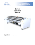
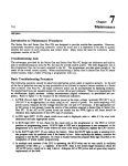
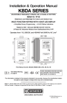
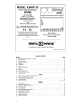
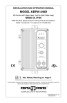
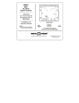
“The Right Control for Your Application.”
12095 NW 39 Street, Coral Springs, FL 33065-2516
Telephone: 954-346-4900; Fax: 954-346-3377
KB Electronics, Inc.
.%9),QVWDOODWLRQDQG2SHUDWLRQ0DQXDO6XSSOHPHQWDO,QIRUPDWLRQ
IRU'XDO9ROWDJH0RGHOV.%9)'3DUW1RDQG.%9)'3DUW1R*
This document is supplied with Models KBVF-22D (Part No. 9572) and KBVF-26D (Part No 9496G).
IMPORTANT: The following information and instructions are to be used as a supplement to the KBVF Installation and Operation Manual (Part
No. A40288) until the new manual is available with the addition of Models KBVF-22D (Part No. 9572) and KBVF-26D (Part No. 9496G). The
KBVF Series has been changed to a second generation version (2G). The General Performance Specifications have not changed. This 2G
version has an additional Frequency Multiplier Jumper, a single Input Line Voltage Selection Jumper, and an additional connector for
accessories. The KBVF manual must be read and understood before attempting to operate this control. For further assistance, contact our
Sales Department at 954-346-4900 or Toll Free at 800-221-6570 (outside Florida).
Also see KBVF 2G Version Supplemental Connection Diagrams and Jumper Settings (Part No. A40090G).
Table 1 - Electrical Ratings
Model
Part No.
KBVF-22D
1
9572
KBVF-26D
2
9496G
AC Line Input
Maximum
Current
Volts AC
(Amps AC)
(50/60 Hz)
115
6.0
208/230
3.8
115
22.0
208/230
14.0
Voltage Range
(Volts AC)
Motor Output
Maximum
Continuous Load Current
(RMS Amps/Phase)
Maximum
Horsepower
(HP (kW))
0 - 230
1.5
¼ (.18)
0 - 230
5.5
1½ [2]1 (1.13) [1.5]1
Notes: 1. Model KBVF-22D CL Trimpot Range (Amps AC): 0.9 - 2.8 (Factory Setting: 2.4). 2. Model KBVF-26D CL Trimpot Range (Amps
AC): 3.5 - 10.5 (Factory Setting: 8.8). Model KBVF-26D is rated 2 HP (1.5 kW) for most premium efficiency motors.
Figure 1 - Model KBVF-26D Mechanical Specifications (Inches/mm) and Control Layout
1
Setting Selectable Jumpers
This control has selectable jumpers which may have to be set before the control can be used. See Figure 1, above, for the location of
jumpers. WARNING! Disconnect the AC line before changing position of jumpers. See Section III, on pages 14 - 16 of the manual.
1.1
AC
control
Line
Input
Voltage
Selection
(Jumper
"!#!%$&'J1()on
*'Upper
(,+-. /"PC
$(0*1#Board):
(234! This5768
. 9 can
:#;3operate
<
=standard
.
,>?208
@3-230
=Volt
:
/AC
>
&-A50/60
B>
208/230 Volt AC line input (Jumper J1 in the "230V" position). To operate the control from a 115 Volt AC line input, set Jumper J1
to the "115V" position. See Figure 2, on page 2.
WARNING! Do not change jumper position with the AC line connected. Be sure proper input voltage is applied
to the control corresponding to jumper setting. Connecting a 230 Volt AC line with Jumper J1 set to the "115V" position
will permanently damage the control. "115VAC" and "230VAC" labels are provided. Use the appropriate label to identify
the correct input voltage after setting Jumper J1.
(A42128) - Rev. E00 - 10/18/2004 - Z2747E00
Page 1 of 2
“The Right Control for Your Application.”
12095 NW 39 Street, Coral Springs, FL 33065-2516
Telephone: 954-346-4900; Fax: 954-346-3377
KB Electronics, Inc.
.%9),QVWDOODWLRQDQG2SHUDWLRQ0DQXDO6XSSOHPHQWDO,QIRUPDWLRQ
IRU'XDO9ROWDJH0RGHOV.%9)'3DUW1RDQG.%9)'3DUW1R*
Figure 2 - AC Line Input Voltage Selection (Jumper J1)
230 Volt AC Line Input
(Factory Setting)
115 Volt AC line Input
1.2
Motor Frequency Selection (Jumpers J1 and J2, on the Lower PC Board): The control is factory set to operate 60 Hz motors
(Jumper J1 factory set to the "60Hz" position and Jumper J2 factory set to the "X1" position). See Figure 3, below. To operate 50 Hz
motors, set Jumper J1 to the "50Hz" position. (Be sure that Jumper J2 is set to the "X1" position.) To operate 120 Hz motors, be
sure that Jumper J1 is set to the "60Hz" position and set Jumper J2 to the "X2" position. To operate 100 Hz motors, set Jumper J1
to the "50Hz" position and set Jumper J2 to the "X2" position.
Figure 3 - Motor Frequency Selection (Jumpers J1 and J2)
60 Hz Motor Operation
(Factory Setting)
2
3
50 Hz Motor Operation
100 Hz Motor Operation
AC Line Fusing
Install a fuse or circuit breaker in the AC line. Fuse each conductor that is not at ground potential. See Table 2, below. See Section VI,
on page 21 of the manual.
Model
Part No.
KBVF-22D
9572
KBVF-26D
9496G
Table 2 - Fuse Selection Chart
AC Line Voltage
Maximum AC Line Current
(Volts AC)
(Amps AC)
115
6.0
230
3.8
115
22.0
230
14.0
AC Line Fuse
(Amps)
8
5
30
20
CL Trimpot Adjustment
Figure 4, below, shows the CL Trimpot range for Model KBVF-22D. Figure 5, below, shows the CL Trimpot range for Model KBVF-26D.
See Figure 1, on page 1 of this Supplemental Information, for the location of trimpots. For other trimpot settings, see Section IX, on pages
24 - 29 of the manual.
Figure 4 - Model KBVF-22D CL Trimpot Range
4
120 Hz Motor Operation
Figure 5 - Model KBVF-26D CL Trimpot Range
Optional Accessories
CON3 is used for optional accessory modules. The planned accessory modules are: Updated Input Signal Isolator, Modbus
Communication, External Dynamic Brake, Multi-Speed Board, Digital Programmer/Readout, and Drive-Link™ PC Programming. See
Figure 1, on page 1 of this Supplemental Information, for the location of CON3.
(A42128) - Rev. E00 - 10/18/2004 - Z2747E00
Page 2 of 2
INSTALLATION
AND
OPERATING
INSTRUCTIONS
KBVF
Adjustable Frequency Drive
Variable Speed /Soft-Start AC Motor
Control
with I2 t Electronic Overload Protection
for 3-Phase Induction Motors through 1 HP
!
See Safety Warning on Page 3
This Manual Covers the Following Model Numbers
KBVF-13, 23, 23D, 14, 24 and 24D
The information contained in this manual is intended to be accurate. However, the manufacturer
retains the right to make changes in design which may not be included herein.
™
See Page 4
A COMPLETE LINE OF MOTOR DRIVES
TABLE OF CONTENTS
Section
i.
Page
Figures (Continued)
Page
Simplified Setup and
2.
Motor with External Cooling . . . . . . . . . . . 8
Operating Instructions . . . . . . . . . . . . 1, 2
3.
Control Layout . . . . . . . . . . . . . . . . . . . . . 9
ii.
Safety Warning . . . . . . . . . . . . . . . . . . . 3
4A.
KBVF HP
I.
General Information . . . . . . . . . . . . . . . . 4
II.
Important Application Information . . . . . 7
III.
Jumper Settings . . . . . . . . . . . . . . . . . . 14
IV.
Mounting . . . . . . . . . . . . . . . . . . . . . . . 17
V.
Wiring . . . . . . . . . . . . . . . . . . . . . . . . . 17
VI.
Fusing . . . . . . . . . . . . . . . . . . . . . . . . . 21
Mechanical Specifications . . . . . . . . . . . 10
4B.
KBVF HP,
Mechanical Specifications . . . . . . . . . . . 11
5A.
KBVF 1HP
Mechanical Specifications . . . . . . . . . . . 12
5B.
VII. Operation . . . . . . . . . . . . . . . . . . . . . . . 21
KBVF 1HP
Mechanical Specifications . . . . . . . . . . . 13
VIII. LED Status Indicator . . . . . . . . . . . . . . 22
6A.
J1 and J2 Set for 230 Volts . . . . . . . . . . 14
IX.
Trimpot Adjustments . . . . . . . . . . . . . . 24
6B.
J1 and J2 Set for 115 Volts . . . . . . . . . . 14
X.
Limited Warranty . . . . . . . . . . . . . . . . . 30
7.
Jumper (J1) Output Frequency Setting . 15
8.
Available Torque vs Output Frequency . 15
1.
General Performance Specifications . 5, 6
9.
Motor and AC Line Connections . . . . . . 18
2.
Electrical Ratings . . . . . . . . . . . . . . . . . . 7
10A.
Main Speed Potentiometer Connection . 19
3.
Terminal Wiring Information . . . . . . . . . 17
10B.
Signal Following (0 – 5VDC) . . . . . . . . . 19
4.
Fuse Selection Chart . . . . . . . . . . . . . . 21
10C.
Signal Following (0 – 10VDC) . . . . . . . . 19
5.
KBVF Status Indicators . . . . . . . . . 22, 23
11A.
Auto/Manual Selection . . . . . . . . . . . . . . 20
6.
CL Setpoint vs Trip Time . . . . . . . . . . . 27
11B.
Manual Start Switch Connection . . . . . . 20
12.
Forward-Stop-Reverse/Enable . . . . . . . . 20
TABLES
FIGURES
1.
Maximum Allowed
Motor Torque vs Speed . . . . . . . . . . . . . 8
ii
13A-G. Trimpot Adjustments . . . . . . . . . . . . 24– 28
i.
!
SIMPLIFIED SETUP AND OPERATING INSTRUCTIONS
IMPORTANT – You must read these simplified operating instructions before you proceed.
These instructions are to be used as a reference only and are not intended to replace the
detailed instructions provided herein. You must read the Safety Warning before proceeding.
Be sure to read Important Application Information on page 7.
1.
AC POWER.
Use 115VAC rated controls on 115VAC and 230VAC
rated controls on 230VAC. For dual input voltage
controls, be sure the AC line jumpers (J1 and J2
on upper PC board) are both set for the correct
AC line voltage 115 or 230VAC. Connect the AC power
to terminals L1 and L2. Be sure the AC power is
disconnected when making connections to control.
Do not bundle AC power and motor wires with any
other wires to control. When the power is turned on
the “PWR” LED will light and the “ST” LED will flash.
Connect ground (earth) to green ground screw located
on the control chassis.
2.
MOTOR LEADS.
Connect the three motor leads to terminals “U,” “V,” and “W.”
Be sure motor is wired for proper voltage: 208-230VAC only.
Motor cable length should not exceed 100 feet – special reactors
may be required – consult factory.
1
3.
MOTOR FREQUENCY SELECTION.
Control is factory set for 60 Hz and 50/60 Hz motors. For 50 Hz motors, completely
remove jumper J1 on lower PC board. (Note: In 50 Hz mode, DECEL trimpot becomes
adjustable boost.) For 120 Hz over speed operation, place jumper J1 in the 120 Hz
position.
4.
TRIMPOT SETTINGS.
The KBVF has been factory set for most applications. For readjustment procedures,
see sec. IX, p. 24.
5.
POTENTIOMETER CONNECTIONS.
Connect the 5K ohm potentiometer to
terminals P1, P2 and P3 as shown
in fig. 10A, p. 19.
6.
SIGNAL FOLLOWING.
For signal following, an isolated
0-5VDC must be used.
Connect signal (POS) to P2 and signal (NEG) to P1 (Note: For signal following, the MIN
trimpot must be set to zero - CCW). Warning! Do not earth ground any input signal
wiring.
7.
FUSING.
Install a fuse or circuit breaker in the AC line. Fuse each conductor not at ground
potential. See sec. VI, p. 21 for recommended fuse size.
2
ii.
SAFETY WARNING! — PLEASE READ CAREFULLY
This product should be installed and serviced by a qualified technician, electrician
or electrical maintenance person familiar with its operation and the hazards involved.
Proper installation, which includes wiring, mounting in proper enclosure, fusing or other
overcurrent protection and grounding, can reduce the chance of electric shocks, fires or
explosion in this product or products used with this product, such as electric motors,
switches, coils, solenoids and/or relays. Eye protection must be worn and insulated
adjustment tools must be used when working with control under power. This product is
constructed of materials (plastics, metals, carbon, silicon, etc.) which may be a potential
hazard. Proper shielding, grounding and filtering of this product can reduce the emission
of radio frequency interference (RFI) which may adversely affect sensitive electronic
equipment. If information is required on this product, contact our factory. It is the
responsibility of the equipment manufacturer and individual installer to supply this safety
warning to the ultimate user of this product. (SW effective 11/92)
This control contains electronic Start/Stop and Enable circuits that can be used to
start and stop the control. However, these circuits are never to be used as safety
disconnects since they are not fail-safe. Use only the AC line for this purpose.
The input circuits of this control (potentiometer, start/stop, enable) are not isolated
from AC line. Be sure to follow all instructions carefully. Fire and/or electrocution
can result due to improper use of this product. After disconnecting AC power, high
voltage exists on this control until both LED’s are extinguished.
3
This product complies with all CE directives pertinent at the time of manufacture.
Contact factory for detailed installation instructions and Declaration of
Conformity. Installation of a CE approved RFI filter (KBRF-200A, KB P/N 9945A or
equivalent) is required. Additional shielded motor cable and/or AC line cables may be
required along with a signal isolator (SIVF, KB P/N 9474 or equivalent).
I.
GENERAL INFORMATION.
The KBVF Adjustable Frequency Drive is designed to provide variable speed control of
standard three-phase AC induction motors. Adjustable linear acceleration and deceleration
are provided, making the drive suitable for soft start applications. The output voltage is
sinewave coded PWM operating at 16 kHz, which provides high motor torque, high
efficiency and low noise. The KBVF is a full featured drive, and due to its user friendly
design, it is easy to install and operate. Simple trimpot adjustments eliminate the computerlike programming required on other drives. However, for most applications, no adjustments
are necessary.
The KBVF main features include Adjustable RMS Current Limit and I2t Motor Overload
Protection. Adjustable Slip Compensation provides excellent load regulation over a wide
speed range. Power Start™ delivers over 200% motor torque to insure startup of high
frictional loads. Several models, through 1 HP, are available to control a standard 208230VAC - 50, 60 and 50/60Hz motor from either a 115 or 230VAC-50/60Hz AC line. The
KBVF is easily tailored to specific requirements via selectable jumpers, such as Frequency
Range (0-60, 0-50, 0-120Hz), Manual/Auto Restart, and Forward-Stop-Reverse operation.
Other standard features include Electronic Inrush Current Limit (EICL™), which eliminates
harmful AC line inrush current, and a built-in dV/dT filter, which reduces harmful voltage
spikes to the motor. Also, two LED indicator lamps provide the user with diagnostic
information. The drive is housed in a versatile U-frame chassis, which facilitates mounting
and wiring.
4
TABLE 1 – GENERAL PERFORMANCE SPECIFICATIONS (All Models)
Parameter
Specification
Factory Setting
±10
—
Maximum Input Voltage Range,
115 VAC Models (VAC)
97 – 135
—
Maximum Input Voltage Range,
230 VAC Models (VAC)
195 – 270
—
Maximum Load (% Current Overload for 2 Minutes)
150
—
Switching Frequency - at Motor (kHz)
16
—
Signal Following Input Voltage (VDC)*
0–5
—
Signal Following Input Resolution (bits)
8
—
0 – 40
0
50, 60, 120
60
70 – 110
100
50:1
—
Recommended AC Line Input Operating Range
(% of nominal 115/230 VAC)
Minimum Speed Trimpot Range
(% of frequency setting)
Output Frequency Setting (Hz)
Maximum Speed Trimpot Range
(% of frequency setting)
Speed Range (ratio)
*Isolated Input Signal must be used
5
General Performance Specifications (Continued)
Parameter
Specification
Factory Setting
Acceleration Trimpot Range (secs)
.3 – 20
1.5
Deceleration Trimpot Range (secs)
.3 – 20
1.5
Boost Trimpot Range (50 Hz only) (%)
6 – 30
—
Slip Compensation Trimpot Range
(Volts/Hz/Amp)
0–3
1.5
Current Limit Trimpot Range - HP (amps AC)
1.5 – 4.5
3.8
Current Limit Trimpot Range - 1 HP (amps AC)
2.5 – 7.5
6.0
2.5
—
0-45
—
6
—
Bus Overvoltage Trip Point (VDC)
(Equivalent AC Line Volts – 230 VAC Line)
400 (283)
—
Bus Undervoltage Trip Point (VDC)
(Equivalent AC Line Volts – 230 VAC Line)
260 (184)
—
Speed Regulation (0-Full Load
30 to 1 Speed Range) (%Base Speed)
Operating Temperature Range (º C)
Overload Protector Trip Time
(Stalled Motor) (Secs)
6
TABLE 2 – ELECTRICAL RATINGS
KB Part
No.
Input Voltage
(VAC– 50/60 Hz)
Single Phase
Nominal
Output
Voltage
(VAC)
Maximum
Horsepower
Rating
HP, (KW)
Maximum
Continuous
Output Load
Current (RMS
Amps/Phase)
Maximum
AC Line
Input
Current
(Amps AC)
KBVF-13
9957
115
0 – 230
1/2, (.37)
2.4
11.0
KBVF-23
9958
230
0 – 230
1/2, (.37)
2.4
7.0
KBVF-23D
9959
115/230
0 – 230
1/2, (.37)
2.4
11.0 / 7.0
KBVF-14
9977
115
0 – 230
1, (.75)
4.0
16.0
KBVF-24
9978
230
0 – 230
1, (.75)
4.0
10.0
KBVF-24D
9979
115/230
0 – 230
1, (.75)
4.0
16.0 / 10.0
Model No.
II.
IMPORTANT APPLICATION INFORMATION.
Most fan-cooled (TEFC and open ventilated) 3-phase motors will overheat if used with
an inverter beyond a limited speed range at full rated torque. Therefore, it is necessary
to reduce motor load as speed is decreased. Note: Some fan cooled motors can be
used over a wider speed range. Consult motor manufacturer for details.
!
WARNING! There may be some motors whose characteristics may cause
overheating and winding failure under light load or no load conditions. If the
motor is operated in this manner for an extended period of time, it is recommended that
the unloaded motor amperage be checked from 2-15 Hz (60-450 RPM) to ensure motor
current does not exceed the nameplate rating. Do not use the motor if the motor
current exceeds the nameplate rating.
...Continued on page 8
7
Inverter duty and
FIG. 1 – MAXIMUM ALLOWED MOTOR TORQUE vs SPEED
most totally
enclosed
nonventilated
(TENV) motors can
provide full rated
motor torque over an
extended speed
range without
overheating see
fig. 1.
!
Therefore, it is
recommended
that this control be used with
inverter duty and totally enclosed
FIG. 2 – MOTOR WITH EXTERNAL COOLING
nonventilated (TENV) motors.
If external fan cooling is provided,
open-ventilated motors can also
achieve an extended speed range
at full rated torque. A box fan or
blower with a minimum of 100 CFM
is recommended. Mount the fan a
few inches from the motor so it is
surrounded by the air flow.
8
FIG. 3 – CONTROL LAYOUT
Illustrates factory setting of jumpers and approximate setting of trimpots
9
FIG. 4A – KBVF HP MECHANICAL SPECIFICATIONS – INCHES / [mm]
10
FIG. 4B – KBVF HP MECHANICAL SPECIFICATIONS – INCHES / [mm]
11
FIG. 5A – KBVF 1 HP MECHANICAL SPECIFICATIONS – INCHES / [mm]
12
FIG. 5B – KBVF 1 HP MECHANICAL SPECIFICATIONS – INCHES / [mm]
13
III. JUMPER SETTINGS.
A. Dual Voltage Controls – Models KBVF-23D and KBVF-24D have the capability of
operating standard 208-230VAC - 50/60 Hz, 3-phase motors from either a 115VAC
or 230VAC - 50/60 Hz AC line. The jumpers are factory set for 230VAC - 50/60 Hz.
Use jumpers J1 and J2 on the top PC board to change the voltage input.
FIG. 6A – J1 & J2 SET TO 230 VOLTS
FIG. 6B – J1 & J2 SET TO 115 VOLTS
Warning! Do not change jumper position with AC line connected. Be
sure proper input voltage is applied to control corresponding to
jumper
setting. Connecting 230VAC to a 115VAC control input will permanently damage
control. “115VAC” and “230VAC” labels are provided. Use the appropriate label
to identify the correct input voltage after setting jumpers.
B. Motor Frequency – The controls are factory set to operate 60 Hz and 50/60 Hz
motors. For 50 Hz motors, completely remove jumper J1 on lower PC board.
Note: When the control is set for 50 Hz operation, the DECEL trimpot will
automatically change to adjustable boost. See sec. IX, G, p. 28.
14
FIG. 7 – JUMPER (J1) OUTPUT FREQUENCY SETTING
The control can also operate 60 Hz and 50/60 Hz motors (not 50 Hz motors) in an
over speed mode. Note: In this mode, motor will produce full rated torque up to 60
Hz. Above 60 Hz, torque will linearly
FIG. 8 – AVAILABLE TORQUE vs
reduce to 50% at 120 Hz.
OUTPUT FREQUENCY
C. Auto/Manual Operation.
i. Auto Operation: The control
is factory set to start
automatically each time the
AC line is connected. It will
also automatically start when
recovering from faults due to
overvoltage, undervoltage
and short circuit. If an I2t fault
occurs due to a prolonged
overload, the control must be
manually restarted.
15
Note: The control can be restarted due to an I2t fault by one of the following
methods:
1. Disconnect and reconnect the AC power (“ST” LED must change from flashing
green to Red/Yellow flash - approximately 15 seconds.)
2. Turning the main speed pot to zero (MIN speed trimpot must be set to “zero”
speed in order to reset with main speed pot).
3. Use Enable contact. See section V, F, on page 20.
Note: If the control trips in I2t, the motor may be overloaded. Check motor current
with an AC ammeter. (Use RMS responding meter.) Also, the CL setting may be set
too low (see sec. IX, E, p. 26).
ii. Manual Operation: To operate in the manual mode the A/M jumper must be
removed and the 2-wire connector (supplied) must be installed. See sec. V, E,
p.20. for complete details.
D. Forward - Reverse – The controls are factory set for “Forward” operation. If, after
wiring the control, it is determined the motor direction is incorrect, simply change the
F-S-R jumper position from “F-S” to the “S-R” position.
WARNING! (Be sure to disconnect power and wait for the “PWR” LED
to extinguish.)
See sec. V, F, p. 20 for complete details on using the F-S-R function.
Note: Two motor leads can be interchanged to change rotation.
16
IV. MOUNTING.
Mount the control on a flat surface free of moisture, metal chips, and other
contamination, including corrosive atmosphere, that may be harmful. For maximum
cooling efficiency, mount the control with fins or sides in a vertical position. If controls
are to be mounted in an enclosure, allow at least 6" x 8" x 12" for HP and 8" x 8" x 16"
for 1 HP. Also, mount control as close as possible to the bottom of the enclosure.
When mounting the 5K remote speed potentiometer, be sure to install insulating disc
between potentiometer and inside of front panel.
Warning! Do not use Start/Stop or Enable circuits as an emergency
stop or severe injury may result.
Warning! Do not wire control with power on. Electrocution or death
may result.
V.
WIRING.
(Use the quick connect terminals provided for AC line, motor and speed pot wiring.)
TABLE 3 – TERMINAL WIRING INFORMATION
Terminal
Designation
AC Line
Motor
Potentiometer
Supply Wire Gauge
Connection
Designation
Type
of Connector
Minimum
Maximum
L1, L2
1/4" QD
16
14
U, V, W
1/4" QD
16
14
P1, P2, P3
1/4" QD
22
18
17
A. AC Line – Wire the
FIG. 9 – MOTOR AND AC LINE CONNECTIONS
correct input AC
line voltage 115,
230VAC - 50/60 Hz
to terminals L1 and
L2, depending on
model number and
jumper selection
for dual voltage
models. Be sure
to connect proper
input voltage to
control catastrophic
control failure can result due to improper voltage. It is recommended that a
fuse be installed on each ungrounded conductor. Do not fuse neutral conductors.
Follow NEC or other electrical codes that apply. See sec. VI, page 21 for
recommended fuse size.
Be sure to ground chassis using green ground screw. Do not ground (earth)
any signal connections. See fig. 9.
B. Motor – Connect motor wires to terminals “U,” “V” and “W.” It is recommended
that the cable length be limited to 100 feet between control and motor. See fig. 9.
Note: If cable length is greater than 100 feet, special reactors may have to be
installed. Important! These controls are designed for 208 - 230 VAC motors
- be sure motor is wired correctly.
18
IMPORTANT - Do not bundle low voltage signal wiring (main speed
potentiometer, signal following, manual start or forward-stop-reverse/enable)
with any main power wiring from AC line or motor. For all signal wiring over 18"
shielded cable is recommended. Do not ground (earth) shield.
C. Speed Potentiometer – Connect
speed potentiometer as shown . The
high side is wired to P3 and the wiper
is wired to P2. Wire the low side to P1
- do not ground (earth) low side of
potentiometer or catastrophic
control failure will result.
FIG. 10A – Main Speed
Potentiometer Connection
D. Signal Following - The control may
be operated with a 0 - 5VDC
isolated signal in lieu of the main speed potentiometer. Connect pos (+) signal to
P2 and neg (–) to P1. Do not ground neg (–) signal wire.
FIG. 10B – SIGNAL FOLLOWING
0 – 5VDC (Isolated)
FIG. 10C – SIGNAL FOLLOWING
0 – 10VDC (Isolated)
Note: For proper operation, “MIN” trimpot must be turned to zero (CCW). If 0-10VDC
operation is required, a resistor network can be added as per fig. 10C. If an isolated
signal is not available, a separate signal isolator must be used (KBSI-240D or
equivalent). Do not ground (earth) signal wiring.
19
E. Manual Start Mode - To operate in the manual
start mode the A/M jumper must be
removed and the 2-wire connector
(supplied) must be installed.
The connector must be wired to a
momentary reset switch or contact.
See fig. 11B. In the Manual mode the
control will trip due to all faults, overvoltage,
undervoltage, short circuit and I2t and
remain tripped even when the fault
condition is corrected. (See LED
diagnostics, sec. VIII, p. 22.) The control
must be reset manually by closing the
A/M contacts. Also, the control must
be restarted each time the AC line
is interrupted.
FIG. 11A – AUTO/MANUAL
SELECTION
FIG. 11B – MANUAL START
SWITCH CONNECTION
F. Forward-Stop-Reverse/Enable - The KBVF may be controlled in several ways using
the Forward-StopFIG. 12 – FORWARD-STOP-REVERSE/ENABLE
Reverse/Enable
circuit. Remove
the F-S-R jumper
and install the
3-wire connector
(supplied).
The control can
now be made to
instantly reverse or start/stop electronically (Enable). See fig. 12 for Start/Stop Enable and Forward-Stop-Reverse connections.
20
VI. FUSING.
It is recommended that a fuse or circuit breaker be used on each AC line connection not
at ground potential. Do not fuse neutral or ground connections. Use a normal or slow
blow fuse according to the table below:
TABLE 4 – FUSE SELECTION CHART
AC Line Voltage
Max AC Line Current
AC Line Fuse (Amps)
KBVF-13
Model
115
11.0
15
KBVF-23
230
7.0
10
115
11.0
15
KBVF-23D
230
7.0
10
KBVF-14
115
16.0
20
KBVF-24
230
10.0
15
115
13.0
20
230
10.0
15
KBVF-24D
VII. OPERATION.
Warning! Read Safety Warning on page 3 before attempting to
operate. Severe injury or death may result.
After all wiring and setup is completed and rechecked, the control can be powered up.
The main speed potentiometer should initially be set at the minimum position (CCW) and
gradually rotated clockwise to increase motor speed. Check status LED’s to verify proper
operation. See sec. VIII, p. 22.
21
TABLE 5 – KBVF STATUS INDICATORS
LED Ref.
Function
“PWR” (Power)
LED Color
Normal Control Operation
Slow Flash
Green
CL (current limit)
Steady
Red
I t
Quick Flash
Red
Short Circuit
slow Flash
Red
Undervoltage
Quick Flash
Red/Yellow
Overvoltage
Slow Flash
Red/Yellow
Stop
Steady
Yellow
Bus & Power Supply
Steady
Green
2
“ST” (Status)
State(1)
VIII. LED STATUS INDICATORS.
The KBVF adjustable frequency drive contains two LED status indicators. The first LED
is a tricolor lamp (ST) that indicates a fault or abnormal condition. The information
provided can be used to diagnose an installation problem, such as incorrect input voltage,
overload condition and control circuit miswiring. It also provides a “normal” signal that
informs the user that all control and micro processor operating parameters are proper.
The second LED is a Power On indicator (PWR) that senses the presence of the bus
voltage and the operation of the main control logic power supply. The status functions are
summarized in table 5.
22
Controller Status
in Auto Mode
Controller Status
in Manual Start Mode
LED Color – Recovered Fault
(Manual Mode)
Run
Run
—
Run
Run
Green(2)
Trip(4)
Trip(4)
Green(2)
Shutdown(3)
Trip(4)
—
(3)
Shutdown
(4)
Trip
Red/Yellow/Green(5)
Shutdown(3)
Trip(4)
Red/Yellow/Green(5)
Shutdown(3)
Shutdown(3)
Green(2)
—
—
—
(1) Slow flash: 1 sec. on, 1 sec. off; Quick flash: .25 sec. on, .25 sec. off.
(2) When control recovers from CL or Stop, the Status LED returns to the “normal” flashing green.
(3) Shutdown: Control will “stop” but will resume operation after fault is cleared.
(4) Trip: Control will “stop” and not restart when fault is cleared. See instructions for restart procedure, sec. V,
E, p. 20.
(5) If a fault occurs in the manual start mode, such as undervoltage or loss of AC power, the drive will trip. The
status “ST” LED will begin to quick flash Red/Yellow. The drive cannot be restarted if the undervoltage
condition persists. When the voltage returns to normal, the “ST” LED will begin to flash Red/Yellow - Green.
This signifies that there was an undervoltage or loss of voltage condition that has been corrected. The
control can now be restarted with the manual start contact.
23
IX. TRIMPOT ADJUSTMENTS
These controls contain trimpots which have been factory adjusted for most applications.
Paragraph 4, on page 2, illustrates the location of the trimpots and their approximate
adjustment positions. Some applications may require readjustment of the trimpots in
order to tailor the control to exact requirements. (See table 1, pages 5 and 6, for range
and factory setting of trimpots.) Readjust trimpots as follows:
WARNING! Do not adjust trimpots with main power on if possible.
If adjustments are made with power on, insulated adjustment tools
must be used and safety glasses must be worn. High voltage exists in this
control. Electrocution and/or fire can result if caution is not exercised. Safety
Warning on page 3 must be read and understood before proceeding. Failure to
follow the Safety Warning Instructions may result in electric shock, fire or
explosion.
A. Minimum Speed (MIN). The MIN trimpot is used to set the
minimum output frequency of the drive, which sets the
minimum motor speed. The minimum speed is factory set
to zero. Readjust the MIN trimpot as follows:
FIG. 13A – MIN
1. Rotate main speed potentiometer to the minimum
speed position (full counterclockwise).
2. Increase setting of MIN trimpot so that motor runs at
desired minimum speed.
Note: For signal following operation, the MIN trimpot is not operational and must be
set to its minimum position (full counterclockwise).
24
B. Maximum Speed (MAX). The MAX trimpot is used to set the
maximum output frequency of the drive. The maximum speed
is factory set to full rated motor speed. Readjust the MAX
trimpot as follows:
FIG. 13B – MAX
1. Rotate main potentiometer to maximum speed position (full
clockwise).
2. Adjust MAX trimpot to desired setting of motor speed.
C. Acceleration (ACC). The ACC trimpot sets the time it takes
the motor to reach full speed from an initial zero start.
The trimpot is factory set to approximately 1.5 seconds.
Adjust the ACC trimpot as required for the application.
See fig. 13C.
FIG. 13C – ACC
Note: When the control is set for 50 Hz operation,
the ACC trimpot will automatically change to adjustable
acceleration and deceleration.
NOTE: Rapid acceleration may cause the current limit
circuit to activate. This will automatically extend the
acceleration time.
D. Deceleration (DEC). The DEC trimpot sets the time it will take the motor to reach
zero speed from an initial full speed setting. The trimpot is factory set to approximately
1.5 seconds. Adjust the trimpot as required for application.
Note: When the control is set for 50 Hz operation, the DEC trimpot will automatically
change to Adjustable Boost. See sec. IX, G, p. 28.
25
Application Note: On applications with high inertial
loads, the deceleration may automatically increase in time.
This will slow down the rate of speed decrease to prevent
the D.C. bus voltage from rising to the overvoltage trip
point. This function is called regeneration protection.
It is recommended that for very high inertial loads
that both the ACC and DEC trimpots be set to a
minimum of 10 seconds.
Fig. 13D – DEC
E. Current Limit with I2t Shutdown (CL).
The CL trimpot is used to set the
maximum motor current that occurs in
FIG. 13E – CL SETTINGS (HP and 1HP )
a stalled condition. The CL trimpot is
factory set to approximately 160% of
full control rating (3.8 amps: HP,
6.8 amps: 1 HP). The CL trimpot can
be readjusted as required. See fig.
13E.
The current limit also contains an I2t
trip function. The control will trip
according to a predetermined current
versus time function. The trip curve is directly related to the CL setpoint and can be
changed with the CL trimpot. Table 6, p. 27 relates the CL setpoint to trip time.
The current limit with I2t shutdown is designed to provide motor overload protection.
Readjust the CL trimpot so that it is set to 160% of full rated motor current as follows.
26
1. Connect an AC ammeter in series with one motor phase.
2. Lock motor shaft and quickly adjust desired locked rotor motor current using CL
trimpot.
Note: This adjustment must be made within 6 seconds or I2t trip will occur.
Example: A HP motor has a full load current of 1.8 amps. Set the CL trimpot to
1.8 x 160% = 2.9 amps.
I2t trip will now protect the motor against overloads.
TABLE 6 – CL SETPOINT vs TRIP TIME
Percent of
CL Setpoint
Trip Time
(Minutes)
Control Rating
(%)
Motor Current
(Amps/Phase)
100
.1 (6 sec)
160
3.8
88
.8
140
3.4
75
30
120
2.9
63
∞
100
2.4
F. Slip Compensation (COMP) – The COMP trimpot is used to maintain set motor
speed under varying loads. The factory COMP trimpot setting of 1.5 volts/Hz/amp
provides excellent speed regulation for most motors. The COMP trimpot can be
adjusted for specific applications as required.
1. Wire an AC ammeter in series with one motor phase.
27
FIG. 13F – COMP
2. Run motor and set unloaded speed to approximately 50%
speed (900 RPM on 4-pole 1500/1725 RPM motors).
Using a tachometer, record unloaded speed.
3. Load motor to rated motor nameplate current (AC amps).
4. Adjust COMP trimpot so that loaded RPM is equal to
unloaded RPM.
5. Motor is now compensated to provide constant speed
under varying loads.
G. Boost (When the control is set for 50 Hz motors, the Decel
FIG. 13G – DEC/B
trimpot becomes Adjustable Boost.) Most 60 Hz motors
conforming to NEMA standards can operate from a preset
volts-per-hertz curve. 50 Hz motors generally differ widely in
their characteristics. Therefore, it is necessary to have
Adjustable Boost to obtain maximum motor performance.
Since the boost trimpot was the DEC trimpot in the 60 Hz
mode, it will take on the prior setting of the DEC trimpot. In
the boost mode the trimpot scale is shown in fig. 13G.
In order for the 50 Hz motor to run properly, the boost must be
adjusted. If the application does not require full torque below 10 Hz, the boost trimpot
can be conservatively set at 8% (9 o’clock position).
28
If more precise speed regulation is required due to varying load, the boost can be set
as follows:
1. Place an AC analog RMS ammeter in series with one motor lead. (Generally,
digital or clamp-on meters do not yield accurate readings.
2. Run the motor unloaded* at approximately 4 Hz (or 120 RPM).
*Note: An unloaded motor with excessive boost will draw more current than a
partially loaded motor.
3. Turn up boost until the ammeter reaches the nameplate motor rating.
4. Using the main speed potentiometer, slowly adjust motor speed over a 0 – 15 Hz
(0 – 450 RPM) range. If motor current exceeds nameplate rating, lower boost
setting.
WARNING! TO AVOID MOTOR WINDING OVERHEATING AND FAILURE,
DO NOT OVER BOOST MOTOR.
29
X – LIMITED WARRANTY
For a period of 18 months from date of original purchase, KB will repair or replace
without charge devices which our examination proves to be defective in material or
workmanship.
This warranty is valid if the unit has not been tampered with by
unauthorized persons, misused, abused, or improperly installed and has been used in
accordance with the instructions and/or ratings supplied. The foregoing is in lieu of any
other warranty or guarantee, expressed or implied, and we are not responsible for any
expense, including installation and removal, inconvenience, or consequential damage,
including injury to any person, caused by items of our manufacture or sale. Some states
do not allow certain exclusions or limitations found in this warranty so that they may not
apply to you. In any event, KB's total liability, under all circumstances, shall not exceed
the full purchase price of this unit. (rev 4/88)
Note: DO NOT REPAIR – This control must be returned to a certified factory repair center.
KB Electronics, Inc.
12095 NW 39th Street Coral Springs, FL 33065 • (954) 346-4900 • Fax (954) 346-3377
Outside Florida Call TOLL FREE • (800) 221-6570 • E-mail – [email protected]
www.kbelectronics.com
(A40288) – Rev. D – 6/99