1
Handicom
Symbol for Windows
Personal
Communicator
(Version 4)
© Handicom, 2011, The Netherlands
User Manual
SfW Personal Communicator
28 December 2011
Contents
Introduction..................................................................................................................... 3
1. Window of the Personal Communicator.....................................................................4
1.1 Application modes................................................................................................... 4
1.2 Menu and toolbar..................................................................................................... 5
1.3 Colorbar................................................................................................................... 5
1.4 The chart................................................................................................................. 5
1.5 Vocabulary............................................................................................................... 6
2. Charts and chart settings for grid pages..................................................................10
2.1 Vocabulary Global Properties................................................................................10
2.2 Default settings for fields.......................................................................................10
2.3 Default settings for pages......................................................................................10
2.4 Default settings for speech....................................................................................11
2.5 Start page.............................................................................................................. 11
2.6 Default settings for the sentence bar.....................................................................12
2.7 Create, save and open charts................................................................................12
3. Managing pages......................................................................................................... 13
3.1 Add a page............................................................................................................ 13
3.2 Delete a page........................................................................................................ 13
3.3 Import a page........................................................................................................ 13
3.4 Export a page........................................................................................................ 14
3.5 Rename a page..................................................................................................... 14
4. Page settings.............................................................................................................. 15
4.1 Field layout............................................................................................................ 15
4.2 Page type and page layout....................................................................................15
4.3 Sentence bar options............................................................................................. 15
4.4 Speech.................................................................................................................. 16
4.5 Commands............................................................................................................ 16
4.6 Re-arrange the content of a page: move and copy fields.......................................16
5. Fields: visual content................................................................................................ 17
5.1 Placing symbols: Select Symbol dialog..................................................................17
5.2 Placing symbols: Reference Vocabulary................................................................18
5.3 Adding images from files.......................................................................................19
5.4 Opposite indicator.................................................................................................. 20
5.5 Adding text............................................................................................................. 20
5.6 Re-arrange the content of a field...........................................................................20
5.7 Text of the label..................................................................................................... 21
5.8 Fields with dynamic content...................................................................................21
6. Fields: settings........................................................................................................... 22
6.1 Layout (per field and per symbol or image)............................................................22
6.2 Sentence bar options............................................................................................. 23
6.3 Speech and sounds............................................................................................... 23
6.4 Commands............................................................................................................ 24
6.5 Links...................................................................................................................... 24
7. Free Layout................................................................................................................. 26
7.1 How to start with a free layout chart.......................................................................26
7.2 Cells...................................................................................................................... 29
7.3 Saving your chart................................................................................................... 31
8. Give the user access to symbols and files outside the chart.................................32
© 2011 Handicom, NL
Page 1
User Manual
SfW Personal Communicator
28 December 2011
8.1 Symbols (link to the Concept Browser)..................................................................32
8.2 Images on the computer (link to the Folder Explorer)............................................32
8.3 Sounds and music (link to the Sound Player)........................................................33
9. Commands and command bars................................................................................34
9.1 About commands.................................................................................................. 34
9.2 Command bars...................................................................................................... 35
10. User settings............................................................................................................. 37
10.1 Cursor.................................................................................................................. 37
10.2 Sentence bar....................................................................................................... 37
10.3 Input options: standard or scanning.....................................................................38
10.4 Speech options.................................................................................................... 38
10.5 Synthesizer settings............................................................................................. 39
10.6 Start up with a certain chart and command bar...................................................40
10.7 Import/export user settings..................................................................................40
11. Extra and advanced program options....................................................................41
11.1 Print one or more pages......................................................................................41
11.2 Translate a chart into another symbol language..................................................41
11.3 View all used files................................................................................................ 41
11.4 Change default directories...................................................................................41
11.5 Caching (speed up a slow computer)..................................................................41
11.6 Command line parameters..................................................................................42
11.7 Configure serial port for environment control.......................................................43
12. Scan options............................................................................................................. 44
12.1 Switch connection types......................................................................................44
12.2 Switch number and function (scan technique).....................................................45
12.3 Cursor movement (scan strategy).......................................................................45
12.4 Default action after selection (only for grid pages)...............................................46
12.5 Timer settings (for grid pages AND free layout pages)........................................46
13. Toolbar buttons........................................................................................................ 48
14. Annex 1: Word Prediction........................................................................................ 49
14.1 Starting and using Word Prediction.....................................................................49
14.2 Settings................................................................................................................ 50
15. Annex 2: Grammar Guided Writing.........................................................................51
15.1 Navigation file...................................................................................................... 51
15.2 Speech output..................................................................................................... 51
15.3 Preview row......................................................................................................... 51
15.4 Action history row................................................................................................ 51
15.5 Input for Concept-To-Text conversion.................................................................51
15.6 Concept-To-Text result........................................................................................ 52
Page 2
© 2011 Handicom, NL
User Manual
SfW Personal Communicator
28 December 2011
Introduction
The Personal Communicator is a computer program enabling people without speech to
communicate.
Dynamic screen
The user display is a dynamic screen: on the screen there is an array of fields. If a field is
selected, the Personal Communicator will do something for the user, usually speak one of
more words.
Some fields link to another page: if that field is selected, another page is shown. This is
what 'dynamic screens' are. Charts can hold a virtually unlimited number of fields,
arranged on 1 or more pages.
Since June 2010, Symbol for Windows programs offer the possibility to create pages
without a grid. You can decide for yourself which layout you want to create.
This way, a chart can become a conversation picture, a page in a reading book or a
selection set in the shape of your own house (with a page for each room and even each
cupboard), where you can place all symbols in their natural context.
More about the Free Layout feature can be found in chapter 7.
Input types / alternative control
The user can use the normal mouse or keyboard or any adapted mouse or keyboard
attached to the computer (touch screens, mouse touch pads, etc.). Input using 1or 2
switches is supported through scanning techniques.
Controlling your environment
The Personal Communicator Light is a Communication Aid. Besides that, the Personal
Communicator (normal version) can enable the user to communicate to his environment,
to another computer etc. Each field on a chart can be programmed as an environment
control button, to open doors, switch on lights, change the channel on a television set etc.
You will need third party hardware to do the actual environment control, but the Personal
Communicator can send any command needed to a serial (e.g. USB) port to control this
hardware.
Virtual keyboard
For scan users, the Personal Communicator (normal version) can also be used as a
Virtual Keyboard displayed on screen: the user uses scanning techniques to select fields,
the Personal Communicator sends keystrokes or mouse messages to the same computer
or to another computer.
These three types of communication (to another person, to the environment and to
another computer) can be combined and seamlessly integrated into one communication
chart, giving the user a unified and simple to use device to do all communication.
About this manual
The first part of this manual explains how to make a chart: add pages, fill fields with
symbols, images and text, set different options for fields, etc.
The second part explains how to adjust the program to a particular user: with the choice
of the input method, the selection and configuring of voices, and so on.
© 2011 Handicom, NL
Page 3
User Manual
1.
SfW Personal Communicator
28 December 2011
Window of the Personal Communicator
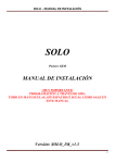
Start the Personal Communicator, for instance by selecting the program icon in the Start
Menu – Programs – Symbol for Windows – Personal Communicator. When you run the
Personal Communicator for the first time, you will see an image similar to this:
By default, the program shows an empty chart with a grid. You can read a previously
saved chart from disk, or start making a new chart either blank or with a grid. (How to
create and edit blank charts, read chapter 7 “Free Layout”.)A “chart" indicates the entire
set of pages.
Settings the program remembers
When closing, the program stores all user settings and will use those settings the next
time you open the program.
1.1
Application modes
The Personal Communicator has two modes:
• User mode or running mode – this is the normal mode the user uses to communicate
• Facilitator mode or settings mode – this mode allows a parent, therapist or technician
to change communication charts, scan settings, speech synthesizer options etc.
The program starts in User mode once you have filled out which files to use (Options –
User files). It will use the chart and the optional command bar.
Otherwise the program starts in Facilitator mode.
Press Alt + F10 to change between the two modes:
You can switch to user mode by pressing Alt + F10.
You can switch back to facilitator mode by pressing Alt + F10.
Page 4
© 2011 Handicom, NL
User Manual
SfW Personal Communicator
28 December 2011
For touch-screen computers, a special alternative has been developed: Press in rapid
sequence the corners of the communication chart in this order:
1. Top Left
2. Top Right
3. Bottom Right
4. Bottom Left
The sentence bar is not visible in facilitator mode, only in running mode. In running
mode it will be visible on every page for which the option 'Sentence bar visible on this
page' is checked (see section 4.3, Sentence bar options).
1.2
Menu and toolbar
Through the menu (below the blue caption) you can operate the program and change all
settings.
The toolbar gives access to a selection of the program’s facilities (see chapter 13,
Toolbar buttons).
1.3
Colorbar
The Colorbar provides an efficient way to set background colors of fields on a page (see
section 6.1.1, Color). The Personal Communicator offers a choice of colors from a palette
of 64 colors. You can change sixteen colors.
You can assign any of these 64 colors to a field, using the toolbar – click on the small
arrow that points downwards - or using the Colorbar.
The hatched box (in the Colorbar located at the top) deletes the field’s background color,
making it transparent.
1.3.1 Define custom colors
The 48 basic colors in the program can’t be changed. But you can define 16 custom
colors. Choose Options – Colors… from the menu or click the toolbar button Select
Color. The standard Windows Color Dialog appears.
1.3.2 Colorbar settings
Choose Options – Colorbar in the menu, to change the colorbar’s settings. A dialog
appears. Through this dialog you can:
• hide or unhide the Colorbar
• position the Colorbar to the top, left, bottom or right of the chart
• set the number of bars (to one or two)
• change the size of the color boxes.
1.4
The chart
A complete communication chart has one or more pages. You can only see one page at a
time. Each page has a number of fields, arranged in a grid of columns and rows, or a
collection of symbols placed freely on the page (with or without a background picture). On
a page with a grid, you can set the number of rows and columns, but all fields will always
be the same size.
Each field, whether it is placed on a grid page or a blank page, can contain one or more
symbols from a database, texts, and images from your own image files. You can also
place a text label, set the background color etc.
Each field can have a link to another page, allowing navigation through the chart by
selecting fields. On a grid page, fields with a link have a folded corner. On a free layout
page, a field with a link has a small paperclip in the top right-hand corner.
Of course each field can also have its own piece of speech or sound, that has to be
played back when the user selects the field.
1.4.1 Navigating
You can select a field by clicking on it with the mouse or by using the cursor keys. There
are different parts of the screen. Only the part of the screen that has the focus (indicated
© 2011 Handicom, NL
Page 5
User Manual
SfW Personal Communicator
28 December 2011
by a thick red line around that section) will react to the keys you press on the keyboard or
the scanningbuttons. Use Tab to shift the focus clockwise, Shift + Tab to move it the other
way round. More about alternative control types can be found in chapter 10.3 “Inputoptions: standard or scanning“.
There are many different ways to go to another page in the chart. You can:
• Press the Ctrl key, hold it down and left-click on a field that refers to another page
• Press Ctrl + G, select a page and click OK
• Use the menu: Find – Go To Page; select a page and click OK
• Press the little arrow next to the page name in the toolbar, and select a page
• Richt-click on a field and choose Go To Page from the pop-up menu; select a page
and click OK.
Tip: use the Backspace key in the facilitator mode to go back to the previous page.
1.4.2 Finding symbols and images in the chart
To find a symbol in the chart,
• Select 'Find – Find' from the menu, or
• Press Ctrl + F, or
• Press the toolbar button ‘Find’
With the dialog that appears you can look for symbols (first two pages) or for images (last
page).
Method 1: Type a name
On the first tab card you can type the name of the symbol you are looking for, or just a few
characters that must form part of the name of the symbol.
Method 2: Browse the categories
When you press the button with the text ‘Select a symbol’ the dialog with the category
structure will be opened. The use of this dialog is explained in section 5.1, Placing
symbols: Select Symbol dialog .
Method 3: Look for a certain file
A Chart can contain imported images. You can look for a particular image if you know the
file name. Type the name of the file or use the browse button to look on the harddisk, a
CD, DVD or USB stick. You can also find imported images through the images/files
manager. For more information on this, read paragraph 11.3 “”.
When you press Enter; the dialog disappears; the Vocabulary displays the first page that
contains a symbol with the given name (method 1), the selected symbol (method 2) or the
given file name (method 3).
Find Next, Find Previous
The symbol, symbol name or imported image may occur in the Chart more than once, on
different pages.
• Choose Find – Find next (or Find previous), from the menu, or
• Press the Find Next toolbar button or the Find Previous toolbar button.
The Chart will display the next match, until the last one is displayed.
1.5
Vocabulary
You can use a Reference Vocabulary to find and place symbols (from symbol databases)
and images (from your computer).
The Vocabulary (also called a graphic menu or a selection set) can give access to:
- A standard vocabulary with all symbols in one symbol database (presuming he has
a license for it). The symbols are arranged according to the standard Symbol for
Windows category structure.
- A special user vocabulary.
- files (such as images and sounds) on the computer, possibly only files in one
folder.
Page 6
© 2011 Handicom, NL
User Manual
SfW Personal Communicator
28 December 2011
And there’s more.
When a page in the Vocabulary is meant to be used for word prediction, the Word
Prediction module will be started (in the Vocabulary window).
When a page in the Vocabulary is meant to be used for grammatical support, the
Grammatical Support module will be started.
See for more information chapter 2.3.1, Page (viewer) type, chapter 4.2, Page type and
page layout, and the appendices.
Tip! With the Image Manager you can make new Symbol for Windows databases, create
a vocabulary based on a new database and use that as reference vocabulary.
1.5.1 Open, hide, unhide or close a Reference Vocabulary
Open a vocabulary
If you want to open an individual vocabulary, choose Tools – Reference Vocabulary –
Open Vocabulary, from the menu.
Vocabulary files have the extension .mnu. .Pcc files can be opened as a reference
vocabulary as well. Select a vocabulary and click OK or press Enter. The reference
vocabulary will be loaded into memory, and will be shown on screen.
Hide/unhide the vocabulary
You can hide the reference chart by closing the window (click the little cross) or by clicking
on the Vocabulary toolbar. The data of the reference chart will still remain in memory; the
reference chart is only hidden.
To unhide it, click the toolbar button again or check the menu option Tools – Reference
Vocabulary – Vocabulary visible.
Close a vocabulary
If you want to release the memory used by the reference chart (e.g. if the system warns
you that the system is running low on memory, or when you notice that the computer
becomes slower), select Tools – Reference Vocabulary – Close Vocabulary. This will
really unload the reference vocabulary from memory, and release the allocated resources.
Note that this is usually not necessary.
1.5.2 Change a Reference Vocabulary
Creating a User Vocabulary with the Vocabulary Maker
In the Vocabulary Maker you can drag-and-drop symbols, images (or image files) and
entire pages or sets of pages from a vocabulary to the User Vocabulary. You can also
print the Vocabulary.
When you have made a user vocabulary, it can be applied to Document Maker. Click on
the menu item Vocabulary – Load… and select the file that you have made for the user.
Creating or editing a User Vocabulary in the Personal Communicator
In the Personal Communicator it is not possible to fill the user vocabulary using another
vocabulary, but it is very well possible to make or edit a User Vocabulary.
First, click on Vocabulary in the menu and then on Allow editing.
Note: Take care to switch off this facility before the end user starts working with
Personal Communicator. The user could accidentally change the individual
vocabulary.
Right-click on the vocabulary to edit it.
Tip: You can open the manual ‘How to make a selection set’ directly
from the Personal Communicator. Right-click on the vocabulary and
choose Vocabulary – Help. Alternatively, you can also find the manual
(Menu.doc and Menu.pdf) in the directory
Handicom/SymforWin/Manuals and open it with Word or the Adobe
Acrobat Reader.
© 2011 Handicom, NL
Page 7
User Manual
SfW Personal Communicator
28 December 2011
1.5.3 Browse a symbol database using the vocabulary window
Instead of an individual vocabulary you can browse a symbol database, using the
vocabulary window.
Choose Tools – Reference Vocabulary – Concept browser. The COMPIC database
will be opened in the vocabulary window with the symbols arranged according to the
Symbol for Windows category structure.
If you want the Concept browser to show another database, choose Properties –
Concept browser. Now you can select a database from a list.
Note: If you don’t have a license for the database, you will see very few symbols.
You can also change the layout of the Concept Browser. Chapter 8.1.2, Layout settings,
explains what you can change and how to do that.
Tip: The user can be given the possibility to switch to the Concept Browser from
the chart or from an individual vocabulary. Choose the field in the chart or
vocabulary and in the field properties choose ‘Switch to Concept Browser’ as the
link type.
The top left field of the Concept Browser refers back to the chart or the individual
vocabulary.
1.5.4 View files or play sounds via the Vocabulary
Choose Reference Vocabulary in the menu Tools and click on Explore folder or Sound
Player.
The reference vocabulary window will now show the contents (images or sounds,
respectively) of one folder on the computer.
By default this is the folder C:\Program Files\Handicom\Symforwin\Images or C:\Program
Files\Handicom\Symforwin\Sounds.
But you can also choose another folder and change many other settings, both for the
content and the layout. An explanation of the settings can be found in chapter 8.2, Images
on the computer (link to the Folder Explorer.
•
1.5.5 Resize the Vocabulary
You can resize reference chart using the splitter between the Communicator Chart and
the reference chart:
• click on the border between the reference chart and the communication chart, the
mouse cursor will change
• if the mouse cursor looks like two lines with to arrows pointing outwards, press and
hold the left mouse button, and move the mouse.
• release the mouse button on the location where you want to have the dividing line
Note: if the area for the reference chart is too small, it will disappear. Find the splitter at
the edge of the window, and move it further inward from the edge.
1.5.6 Browse the Vocabulary
The Vocabulary is structured like a grid of boxes. Each box in the grid can have three
states:
1. It can be empty
2. It can hold one or more symbols, images and texts. When the Vocabulary is used to
view files on the computer, each field contains only one file.
3. It can hold a reference to another page (sub-menu) with symbols or to another folder
on the computer.
The boxes with a reference to another page or to another folder on the computer have a
folded edge like a paper page.
Page 8
© 2011 Handicom, NL
User Manual
SfW Personal Communicator
28 December 2011
When you click on such a field you go to the other page in the vocabulary or to the other
folder on the computer.
The reference in the top left corner returns you to the previous page or the parent folder.
You can select a field by clicking on it with the mouse or by using the cursor keys and
pressing [Enter]. If you have selected a box with a reference to another page, the other
page will be displayed.
Chapter 5.2.2, Finding symbols and images in the Reference Vocabulary, explains how to
find a symbol, image or text in a vocabulary.
© 2011 Handicom, NL
Page 9
User Manual
2.
SfW Personal Communicator
28 December 2011
Charts and chart settings for grid pages
A Communicator Chart is an article of use. So before you start making a chart, you have
to think about the use of it. What is the purpose of this chart? Who is going to use it?
What are the user’s wishes and needs and what are his or her possibilities?
It’s a good idea to put the structure of the chart down on paper, before actually making it.
Don’t add too many pages or too many links, if the user can’t handle a complex structure.
Write the page names down too. To keep the chart neatly arranged, it is important to use
clear page names. Write down which pages have to be grid pages and which ones blank
(free layout) pages. In chapters 2 through 6 you can find information about creating grid
pages. In chapter 7 you can read more about creating free layout pages.
See for more tips and tricks the special guide to making a Vocabulary.
2.1
Vocabulary Global Properties
Adjust the chart settings before adding any grid pages; the chart settings affect the looks
and the settings of every new grid page.
With the Vocabulary Global Properties dialog you can set the overall options for the entire
Communication Chart. If you want to change e.g. the font used for field labels of all fields,
change the label font in the Vocabulary Options dialog. All fields will use this font unless
the setting is overruled on a more detailed level (that is, if a page has its own settings for
fields, or if a field has its own settings).
To open the Vocabulary Properties Dialog, do one of the following:
• Select Properties – Vocabulary Properties, in the menu
• Press the right mouse button and select Vocabulary Properties in the pop-up menu.
• Press the toolbar button Vocabulary Properties.
The following pages are available in the dialog:
• Field – default settings for fields
• Page – default settings for pages
• Speech
• Global – to set the start page
• Sentence bar
2.2
Default settings for fields
The page ‘Field’ allows you to set the default field layout. You can set:
• the default background color
• the place, font and scaling of the labels
• graphic drawing options
• the font to use for text that comes in the place of symbols.
The option ‘stretch’ (graphic settings) means the image is stretched so that it takes up all
space in the field.
2.3
Default settings for pages
2.3.1 Page (viewer) type
The tab menu Page allows you to set the default page type, at the bottom.
Vocabulary
For ‘normal’ Vocabulary pages you can choose between ‘Grid: one image per field’ and
‘Grid: multiple images per field’. The second one is the default type.
Word prediction
Page 10
© 2011 Handicom, NL
User Manual
SfW Personal Communicator
28 December 2011
Though it is possible to choose this viewer type as the default, it will almost never happen
that most pages in a chart are of this type. This page type is usually the setting for an
individual page; see chapter 4.2, Page type and page layout.
Grammar guidance
When a page in a Vocabulary is of the type Grammar Guidance, the program will try (in
running mode) to run Grammar Guidance (one part of FlexLex, a module for linguistic
support) to show this page.
If Grammar Guidance isn’t available, the page will be shown as a normal Vocabulary page
(with multiple images per field). Special Grammar Guidance commands will be ignored.
In a chart with grammar guidance all pages will usually be of this type.
Tips:
- when making a grammar guidance chart it is very useful to open a command bar with
the commands ‘Previous page’ and ‘Start page’;
- to go to the previous page you can also use the Backspace key.
2.3.2 Page layout
The tab menu Page allows you to set the default layout for pages. The default layout
applies to all pages that don’t have their own settings and to every new page.
You can set:
• the number of rows and columns; when creating a new page, it will get the number of
rows and columns set here
• the default page color; note that this color is not visible if the field spacing is set to
zero
• the default link color; fields that refer to another page will by default get this color
• the field border width
• the field border color – note that this color won’t be visible if the field border width is
zero!
• the field spacing (spaces between the fields).
You can not set a default name, because each page name has to be unique in the entire
Communication Chart.
2.4
Default settings for speech
In running mode, the program can say or play something when the user navigates through
the chart, ‘walking over’ the fields, command bar and/or sentence bar. Some users need
this audible feedback to know where the cursor is, because they can’t see it. (More on this
option in paragraph 10.4 “Speech options”)
You can make feedback messages for every field and every page. On this dialog page
you can set a default feedback message for the chart (‘Vocabulary’).
The message will be said when the cursor indicates the whole chart, for instance when
the user has to choose between the sentence bar and the chart.
You can also type feedback messages for fields that refer to
• another page
• the start page
• the previous page.
Note: %s is a formula that extends the text of the feedback message with the name of the
page the field links to. So when the field refers to a page ‘Food’, the text of the feedback
message will be ‘food’ where you type %s.
2.5
Start page
The Start page is the page that will be shown to the user as the start page. When the user
mode starts, this page will be activated.
This setting can also be changed using the Page Manager (Tools – Page Manager in the
menu).
© 2011 Handicom, NL
Page 11
User Manual
2.6
SfW Personal Communicator
28 December 2011
Default settings for the sentence bar
On the tab menu Sentence bar you can change the default settings for the sentence bar:
• Visibility: If the option ‘Sentence bar visible for this page’ is checked, the sentence
bar will by default be visible when a page is displayed in running mode.
• Content: Decide whether the content of fields must be added to the sentence bar
when the user selects them.
• Spaces: Choose if you want the program to add spaces while building the sentence
bar text.
Note: the content of fields with a link is by not placed in the sentence bar when you select
the field. To change this, so that the content of the field with the link will be added to the
sentence bar as well, you have to adjust the settings of the field, see 6.5.4, Option: add
content to sentence bar.
2.7
Create, save and open charts
2.7.1 Creating a new chart (with a grid)
Select File - New from the menu to create a new grid chart. (To create a new blank chart
to fill using free layout, read chapter 7 “Free Layout”.) If the current chart has changed,
you will be asked if you want to save these changes. Alternatively you can press [Ctrl]+N
on the keyboard or press the 'New' toolbarbutton.
2.7.2 Opening an existing chart
Select File - Open from the menu to open an existing chart. If the current chart has
changed, you will be asked if you want to save these changes. Next, locate the file
containing the chart you want to open. Alternatively you can press [Ctrl]+O on the
keyboard or press the 'Open' button on the toolbar.
2.7.3 Saving a chart
Select File - Save or File - Save As from the menu to save the current chart. The first
('Save') saves the chart under the same name, overwriting the existing file.
If you are editing a new chart, the 'Save' function automatically activates the 'Save As'
function. 'Save As' saves the chart, but allows you to enter a new name.
Select the directory you want to save your file in, enter a filename for the chart and press
OK. Alternatively for the 'Save' function you can press [Ctrl]+S on the keyboard or press
the 'Save' button on the toolbar.
The charts that you create with the Personal Communicator version 4.0 and newer,
are by default saved with extension .pccx. This is a new file type, different from
versions 3.4 and older. It means that all imported images are saved with the chart. It is
no longer necessary to move the image files with the chart, when you move the chart
to another computer or send it to a colleague or friend. Choosing the old file format
remains possible. Files with extension .pcc can be opened by older versions of Symbol
for Windows, files with extention .pccx cannot! Furthermore, charts that have been
created using the free layout function, can’t be opened by older versions, even if they
have been given the extension .pcc.
It is advisable to save any document frequently, while you are working on it. Press [Ctrl]+S
as a convenient way to quickly save your document.
Page 12
© 2011 Handicom, NL
User Manual
3.
SfW Personal Communicator
28 December 2011
Managing pages
Managing pages is easy using the Page Manager. To open it, choose Tools – Page
Manager in the menu. Which buttons are enabled depends on the selected page(s).
Note: Links can not be added or deleted using the Page Manager. A link is a reference to
another page. Only fields can hold a reference to another page, so in fact, a link is a
field’s property. See section 6.5, Links, to find out how to add or delete a link (in other
words: how to edit this property).
3.1
Add a page
To add a page,
• select a field and choose Field - Add Page in the menu, or
• richt-click on a field and choose Add page, from the pop-up menu, or
• open the Page Manager (Tools – Page Manager), and click the button ‘Create empty
page’.
A dialog will appear with a suggested name of the new page, e.g. ‘Page 5’. This
suggested name is guaranteed to be unique, but it is not very descriptive. It is a very good
custom to change this name into something more descriptive.
If the new page name is not unique, the Personal Communicator will inform you about
that, and you will have to change the name.
If you have used the Page Manager to add a page, don’t forget to make at least two links:
one from another page in the chart to the new page, and one from the new page to one of
the other pages.
3.2
Delete a page
You must use the Page Manager to delete pages. Open the Page Manager (Tools –
Page Manager), select the page you want to delete and click the ‘Delete’ button.
The page will be deleted and all links to it will be deleted in the entire Communication
Chart.
3.3
Import a page
Personal Communicator pages, saved separately, can be imported in a Personal
Communicator Chart.
A Paper Chart Maker chart, exported as vocabulary page, can be imported in a Personal
Communicator chart as well.
To add such a page to the Personal Communicator chart, you can
• select a field and choose Field – Add page from template, from the menu, or
• richt-click on a field and choose Add page from template, from the pop-up menu
• open the Page Manager (Tools – Page Manager), and click the button ‘Create page
from template’.
Choose a file of the type .vcp and click OK. The program suggests a new page name (in
this case, the filename minus the extension), that you can change if you want. When you
click on OK again, the page is added to the chart. It is stored in the chart file, like all other
pages, so the changes that you make to this page won’t affect the template.
If you have used the Page Manager to add a page from template, don’t forget to make at
least two links: one from another page in the chart to the new page, and one from the new
page to one of the other pages.
Notes:
• From Paper Chart Maker charts only the visual content of the fields will be copied.
Symbols, images, photo’s, texts and the colors used will appear in the new Personal
Communicator page. The other information that the Paper Chart Maker saves in a
© 2011 Handicom, NL
Page 13
User Manual
•
3.4
SfW Personal Communicator
28 December 2011
chart (such as commands that are linked to a field and the size of the chart) will be
neglected.
To a Paper Chart Maker chart, the Personal Communicator will always automatically
add an extra row on top with a link to the “previous page” in the top left field.
Export a page
You must use the Page Manager to export pages from the Personal Communicator
chart.. An exported page can be imported in another Personal Communicator template
page or as a Paper Chart Maker chart.
Open the Page Manager (Tools – Page Manager), select the page you want to export
and click the button ‘Save page as template’. The program suggests a filename that you
can change. You can also change the directory in which the file must be saved, but don’t
change the extension.
Click on OK to save the page in a separate file.
Note:
In a Paper Chart Maker chart only the visual content of the fields will be saved. Symbols,
images, photo’s, texts and the colors used will appear in the new Paper Chart Mkaer
chart. The other information that the Personal Communicator can store in a field (such as
commands that are linked to a field) will be neglected.
3.5
Rename a page
To rename a page, you can use the Page Manager (Tools – Page Manager). Select the
page you want to give another name, click the button ‘Rename page’ and type the new
name. The new name must be unique.
You can also change a page’s name in the Page properties dialog, tab menu ‘Page’, see
section 4, Page settings.
Page 14
© 2011 Handicom, NL
User Manual
4.
SfW Personal Communicator
28 December 2011
Page settings
The default Chart settings, such as the number of rows and columns on a page, can be
overruled by a page’s own settings.
First go to the page of which you want to change the settings.
You can use the Page Manager to do this. To open it, choose Tools – Page Manager in
the menu. Click on the page that you want to change. Then close the Page Manager.
You can also go to another page using the menu Find. Click on Go to page... and
choose the page from the list.
A third possibility is to follow the links in the chart; hold the Ctrl key pressed down and
click on a field that links to another page, to follow the link.
Tip: To go to the previous page you can press the Backspace key.
To change the settings of the page,
• select Properties – Current page, in the menu, or
• press the right mouse button and select Current page, in the pop-up menu, or
• press the toolbar button Page properties.
With the Page properties dialog that opens up, you can set the options for one page in the
Communication Chart. If you want to change e.g. the font used for field labels in all fields
on this page, change the label font of the page. All fields on this page will use this font,
unless the setting is overruled on a more detailed level (that is, in the field settings for one
field).
Setting the options to 'Default' will result in using the options set for the Chart (Properties
- Vocabulary Global Properties, in the menu or pop-up menu).
All the pages that are available in the dialog are discussed in the paragraphs below.
4.1
Field layout
This is very much like the Field properties you can set for the entire communication chart,
but here you set them for one page and not for the whole chart. See section 2.2, Default
settings for fields.
The main difference is that now you can use the default options set for the entire chart.
4.2
Page type and page layout
Apart from the page name, the page properties you can set here are all the same as the
page properties you can set for the entire communication chart. The difference is that you
set them here for one page. See section 2.3, Default settings for pages.
Word Prediction
When a page in a Vocabulary is of the type Word prediction, the program will try (in
running mode) to run Word prediction (one part of FlexLex, a module for linguistic
support) to show this page.
If Word prediction isn’t available, the page will be shown as a normal Vocabulary page
(with multiple images per field). Special Word prediction commands, such as ‘Accept
word’, will be ignored.
Note:
If you reduce the number of rows or the number of columns, the contents of the fields at
the right or bottom edge of the page may get lost.
4.3
Sentence bar options
In the Field Properties dialog, page ‘Sentence bar’, you can change the page settings for
the sentence bar. These are the same as the sentence bar properties that you can set for
the entire communication chart. See section 2.6, Default settings for the sentence bar.
By default, the content of a field with a link is not placed in the sentence bar. To find out
how to change this, read paragraph 6.5.4, Option: add content to sentence bar.
© 2011 Handicom, NL
Page 15
User Manual
4.4
SfW Personal Communicator
28 December 2011
Speech
Open the Page Properties dialog, tab menu ‘Speech’ to set the speech properties for a
page.
Suppress speaker speech
The speaker is the voice that represents the user in communication with other people. It is
possible to suppress the speaker speech for an entire page. This might be useful e.g.
when a page is used for environment control only.
Check the option ‘Suppress speaker speech for entire page’.
Note that the Speaker will not be suppressed for the sentence bar. But you can hide the
sentence bar as well.
Page feedback message
When the user is navigating the chart, the program can generate feedback messages to
let the user know where he or she ‘is’ in the chart. The feedback can be given during
navigation or as a respond to selection.
By default, the feedback message for a page is the page name. But it can also be
something else: the message you type here.
4.5
Commands
The Personal Communicator can execute a series of commands when the user enters or
exits a certain page. The commands should be linked to that page using the Page
Properties dialog, tab menu ‘Commands’.
Press the ‘Edit’ button to add or change the commands for the current page. A dialog will
open where you can select commands from the currently loaded command list.
If no Command is loaded, you will first have to load a Command set: press the ‘Load’
button and select one of the command files (file extension: .cmds) (see section 9.1, About
commands).
Press the Clear button to erase all ‘on enter’ or ‘on exit’ commands from this page.
Note:
If you select commands in the Page Properties dialog, the commands will be copied into
the page. The program executes the command when the user enters or exits the page in
running mode. The file containing the command list is no longer needed, and it is not
necessary to have the file present on the computer of the end-user.
4.6
Re-arrange the content of a page: move and copy fields
You can easily move fields on one page using the drag-and-drop feature:
• Move the mouse over the field you want to move, and press and hold the left mouse
button
• Move the mouse over the field you want to move the other field to
• Release the left mouse button.
The fields will be exchanged.
Tip! Hold the Ctrl key while dragging, to copy the content of the first field and add
it to the second field.
Using the Edit menu or the popup menu you can either copy a field including its content –
choose Copy – or without its content – choose Copy Settings. Then click on the field
where you want to copy to and choose (Edit - ) Paste.
Page 16
© 2011 Handicom, NL
User Manual
5.
SfW Personal Communicator
28 December 2011
Fields: visual content
Fields can be filled with visible and invisible information. This chapter is about the visual
content of each field.
Field properties dialog
With one dialog all field options can be set: the Field Properties dialog.
To open it, do one of the following:
• Double-click on a field
• Select a field, and press Ctrl + Enter on a field
• Select Properties – Current field in the menu
• Press the right mouse button and select Current ffield in the pop-up menu
• Click on the toolbar button Field properties.
Tab menu ‘Contents’
With the first tab menu, ‘Contents’, you can edit the graphical content of the field: one or
more symbols, imported images and texts.
There are three buttons to add graphics:
• Add symbol from database – this will open the Select Symbol dialog described in
below.
• Add image from file – a file open dialog will be opened where you can select the image
you want to use
• Add text – a dialog will be opened where you can type the text you want to use in the
field
The other buttons on the page are
• Left / Right – with these you can re-arrange the graphics: select one graphic (it will get
a blue background) and then select Left or Right
• Delete – delete the selected graphic
• Clear – delete all graphics
This tab menu will be mentioned in every paragraph of this chapter.
5.1
Placing symbols: Select Symbol dialog
To open the Select Symbol dialog you can:
• Press the Select Symbol button on the ‘Contents’ page of the field properties dialog
(see the introduction of this chapter)
• Select a field and choose Field – Select Symbol, from the menu
• Select a field and click the Select Symbol button on the toolbar
• Right-click on a field and choose Select Symbol from the pop-up menu
• Select a field and start typing the name of the symbol you want to place. As soon as
you press a letter or number key (a through z, 1 through 0), the dialog is displayed.
Note: use the ‘Select Symbol’ button in the Field Properties dialog if you don’t want to
replace the field’s contents by the symbol you select!
Concept names and synonyms
The list in the middle contains not symbol names but concepts instead. Of one database,
several symbols can be linked to one concept. For instance, if there are several symbols
for the concept ‘house’, they are all linked to the concept ‘house’.
When you click on a concept name in the list in the middle, only the first symbol that is
linked to the concept is shown in the preview box to the right. If there are more symbols
available for the chosen concept, the buttons Show Previous Synonym and Show New
Synonym will be enabled, indicating the synonym number and the total number of
synonyms available for this concept.
© 2011 Handicom, NL
Page 17
User Manual
SfW Personal Communicator
28 December 2011
Databases
On the right, a list shows which database is currently selected. You can choose another
database, selecting one from the list that unfolds when you click the small arrow key at
the right of the list. The list will only show names of databases that are available for you.
Categories
On the left you see the Symbol for Windows category structure. When you click on the
name of a category, the list in the middle is filled with all concepts that occur in that
category and in the chosen database.
A [+] placed before the name of a category means that there are sub-categories. Click
with the left mouse button on the [+] to unfold a category. Now you can select one of the
sub-categories to be able to browse a smaller selection.
Below the category structure you will find two options which can make searching easier:
1. If the first option is activated, the category structure functions as follows. When you
click on the name of a category that contains subcategories, the list in the middle will
be filled with all concepts, which occur in the chosen database as well as in the chosen
category, and in all its sub-categories. (This is always the case when you click on the
main category, whether this option is activated or not.)
2. When a symbol database doesn’t contain too many symbols, many categories and
sub-categories will be empty or almost empty. Check this option to remove the empty
categories from the category structure and to place the contents of very small subcategories in their ‘parent’-category. When you choose another symbol database, the
category structure will be adapted to that database.
3. The option ‘Remember current category’ makes the dialog remember which category
was open when the dialog is closed. Next time you open the dialog, it will open with the
same category.
Finding a symbol
You can browse the list in the middle very quickly by typing the first letters of the
concept/symbol you look for. First click in the list or in the box on top of that list.
You could also use the Find- and Find Next button to look for a word or the part of a word.
The (part of the) word is looked for in all categories. If a name is found in which the (part
of the) word occurs, the category-list shows to which category it belongs, adding a gray
background to the name of that category.
Note: Keep in mind that the names of concepts can differ from the original symbol names
that are used within each database. And, if you are looking for a particular symbol, don’t
forget to check for synonyms!
Place a symbol
Select a concept name (and if necessary, a synonym) and press Enter or click OK to
place it in the field. The name of the symbol will be used as label of the field. Click Cancel
or press Esc to return to the chart without placing a symbol.
5.2
Placing symbols: Reference Vocabulary
5.2.1 How to place symbols using the Reference Vocabulary
First open a Reference Vocabulary; see chapter 1.5.1, Open, hide, unhide or close a
Reference Vocabulary.
With the mouse, you can simply drag the symbol to the field. Left-click on the symbol,
keep the left mouse button down and move the mouse to the field on the chart before you
release the mouse button.
If you press and hold down the Ctrl key while dropping a field from the reference chart on
a field in the Communication Chart, the contents of the field dragged from will be inserted
in or added to the contents of the field dropped on.
You can also use another method:
1. Right-click on a symbol in the Vocabulary
Page 18
© 2011 Handicom, NL
User Manual
SfW Personal Communicator
28 December 2011
2. Choose Copy from the pop-up menu
3. Right-click on a field on the chart
4. Choose Paste from the pop-up menu
With the keyboard you can only use the Copy and Paste-method.
1. First make sure the Vocabulary is focused (use the Tab key).
2. Browse the database using the cursor keys and the [Enter] key.
3. Select the symbol you want to place and choose Edit - Copy from the menu.
4. Use the Tab key to move the focus to the chart
5. Select the field you want to place the symbol in.
6. Choose Edit - Paste from the menu. The symbol is placed in the field, together with its
name.
Note: It is possible to change a Reference Vocabulary to a limited extent. See chapter
1.5.2, Change a Reference Vocabulary.
5.2.2 Finding symbols and images in the Reference Vocabulary
To find a symbol or image in the Vocabulary, you can use the Find function.
• Select Find – Find in Vocabulary from the menu, or
• richt-click on the Vocabulary and select Find from the pop-up menu.
The dialog that appears is described in paragraph 1.4.2, Finding symbols and images in
the chart.
Find next
The symbol, symbol name or file name that you are looking for may occur in the
Vocabulary more than once, on different pages. To make the Vocabulary display the next
match,
• Choose Find – Find next in Vocabulary, from the menu, or
• rigt-click on the Vocabulary and choose Find next from the pop-up menu.
5.3
Adding images from files
Images can be imported using the Reference Vocabulary, the Field properties dialog, the
menu or pop-up menu, or Windows Explorer.
Tip! If you don’t want the imported image to replace the
content of the field (so, if you want to add it to the field)
then you must use the dialog Field Graphics or the Windows
Explorer.
Using the Reference Vocabulary
This method is the quickest, especially if there are several images in files on the computer
that you want to place in the chart.
1. First make sure that the Vocabulary shows the files in a folder on the computer.
Choose Reference Vocabulary in the menu Tools and click on Explore folder. To
learn more about the different settings for the Folder explorer, read paragraph 8.2
“Images on the computer”.
2. Browse through the folders to find the image file. Drag the image file to a field on the
chart or copy it into a field. The previous paragraph explains in detail how to do that.
Note: If the loaded vocabulary contains imported images, you can copy them into the
Communication Chart just like the other symbols in the vocabulary.
Using the Field Properties dialog
The Field Properties dialog can also be used to import images. Right-click on the field,
select Current field from the pop-up menu and click the button Import Image on the
tab menu ‘Contents’.
The imported image will be added to the field’s contents.
Using the menu/pop-up menu or toolbar
© 2011 Handicom, NL
Page 19
User Manual
SfW Personal Communicator
28 December 2011
Alternatively, you can select a field and then…
• select Field – Import Picture from the menu, or
• press the right mouse button, and select Import Picture from the pop-up menu, or
• click the toolbar button Import Picture.
A dialog will appear where you can browse your computer, looking for the file
containing the image you want to use.
Note! the image you select this way will replace the contents of the active field. If you
don’t want that you will have to open the Field Properties dialog first.
5.4
Opposite indicator
Every single symbol and image can be drawn with a ‘opposite indicator’ in the form of a
cross or a line in one of the colors black, white or red.
Right-click on a field and choose Current field from the pop-up menu; go to the tab menu
Content and select the symbol or image. Then click on the button Options and select the
desired indicator.
For explanation about the other drawing options, see 6.1.3, Settings per symbol or image.
5.5
Adding text
You can have text at the position where usually symbols and images will appear.
The quickest way to add text
• Click the field you want to place an image in and select Field – Text Representation
from the menu, or
• press the right mouse button; select Text Representation from the pop-up menu, or
• select the field you want to add text to, and press Ctrl+R, or
• select the field you want to add text to and click the toolbar button Text
Representation.
A dialog will appear where you enter the text you want to use.
Note! The text you type this way will replace the contents of the selected field.
You can also add text with the Field Properties dialog.
Open the dialog (tab menu ‘Content’) and click the button Add text; then you can type a
text.
If the loaded Vocabulary contains text instead of graphics, you can copy the text into the
Communication Chart just like all symbols in the vocabulary.
5.6
Re-arrange the content of a field
You can use either the field properties dialog, or the drag-and-drop method to move
symbols, images or texts in a field.
To delete one symbol, image or text from a field that contains more than one
symbol/image/text, you have to use the Field Properties dialog. Open the dialog, page
‘Content’; select the symbol, image or text you want to remove and click the button
‘Delete’. The ‘Clear’ button wipes all contents off the field.
Drag and drop: Ctrl-key.
You can rearrange symbols, images or text in a field using the Ctrl key:
Left-click on the symbol, image or text.
Press and hold down the Ctrl key.
Move the mouse until the position is right.
Release the mousebutton.
While dropping on another field, the contents of the field dragged from will be inserted
in or added to the contents of the field dropped on.
Field Properties dialog
Page 20
© 2011 Handicom, NL
User Manual
SfW Personal Communicator
28 December 2011
The tab menu ‘Content’ in the Field Properties dialog contains two buttons to move
symbols, images or text to another position in the field. Select a symbol, image or piece of
text and click the ‘Right’ button to move it one step to the right; or click the ‘Left’ button to
move it one place to the left.
5.7
Text of the label
Each field can have a label. Whether the label is visible or not, and whether its position is
on top of or below the symbol, depends on:
- the chart settings (see section 2.2, Default settings for fields)
- the page settings for fields (see section 4.1, Field layout) and
- the field’s own settings (see section 6.1.2, Settings for label and graphic).
The label will be generated when you place the first symbol in a field, but you can always
change the label of the field. Select the field you want to change the label of, and…
• select Field – Text Label from the menu, or
• press the right mouse button and select Text Label from the pop-up menu, or
• press Ctrl+T, or
• click the ‘Text label’-button in the toolbar.
A dialog will appear where you can type the text for the label.
Alternative:
Set the field label using the Field Properties dialog. Type the text for the label on the tab
menu ‘Content’ (under ‘Field label’).
5.8
Fields with dynamic content
In the case of fields with dynamic content, the visible information depends on the invisible
information...
This is how it works.
To the user, a field with dynamic content looks like a field with a stack of symbols on it.
Every time the user selects the field, the next symbol is shown.
But technically a field with dynamic content is a field with a link to another page. The
symbols of the other page are shown one by one through this field.
To link dynamic content to a field, rightclick on the field and choose Edit dynamic
content. Or, if the page that you want to use as dynamic content already exists, change
the link type of the field; see chapter 6.5.3, Link type.
If no dynamic content was linked to the field before, a new page will be made after you
type a name for the page. Then the new page is opened. On this page static fields will be
visible, but they will (just like links) be ignored by the field with dynamic content.
To edit the dynamic content later on, rightclick on the field and choose Edit dynamic
content again. The underlying page will be opened. Or go to that page using the Page
Selector: look for the name of the current page in the toolbar, click on the arrow next to
the page name, and choose the page from the list that appears.
The fields can be filled just like any other fields with symbols, images and text.
© 2011 Handicom, NL
Page 21
User Manual
6.
SfW Personal Communicator
28 December 2011
Fields: settings
With one dialog all field options can be set: the Field Properties dialog.
To open it, do one of the following:
• Double-click on a field
• Select a field, and press Ctrl + Enter on a field
• Select Properties – Current field in the menu
• Press the right mouse button and select Current field in the pop-up menu
• Select a field and press the toolbar button Field Properties.
All settings that can be done on the first tab menu in the dialog (the tab menu Content)
have been mentioned in chapter 5.
With the second tab menu, ‘Field’, you can edit the general field layout options: the
background color, appearance of the label, graphic drawing options and the font to
use.
The last three pages influence the way the field responds in running mode:
• Speech: specify what speech to use for this field
• Commands: specify any commands to execute when this field is selected
• Link: specify the page this field links to.
6.1
Layout (per field and per symbol or image)
6.1.1 Color
The color of fields can be set in a number of ways.
The Colorbar provides a quick and easy way to color fields. When it is visible, you can
activate a color by clicking on it. (Read section 1.3, Colorbar, to find out how to
hide/unhide the Colorbar and how to change the settings of the Colorbar.)
A small cross in one of the colored boxes shows which color is the active color. If there is
an active color, every mouseclick on a field changes the color of that field into the
currently activated color. You can disable a color by clicking again on the color's box in the
Colorbar, or by selecting another color.
To color a field you can also
• select the field you want to color and choose Field – Field color from the menu, or
• richt-click on the field and choose Field clor from the pop-up menu, or
• click the small arrow next to the toolbar button Color and pick a color.
You can also use the Field properties dialog, tab menu Field. Read the instructions at the
beginning of this chapter to find out how to open that dialog. Click the ‘Select’ button
under ‘Field color’.
6.1.2 Settings for label and graphic (per field)
The tab menu Field of the Field Properties dialog allows you to change the
• Label Settings (placement, scaling and font),
• Graphic Settings (scaling for symbols/images, and font for text), and the
• Color of a field.
The label can be omitted, or placed above or below the symbols.
When a label is too long to fit in a field, a smaller font size will be used if the option ‘Shrink
long labels’ is checked.
The option ‘stretch’ (graphic settings) means the image is stretched so that it takes up all
space in the field.
Default
Every setting has an option 'default'. The default options of a field are first defined in the
Vocabulary Global properties, see section 2.2, Default settings for fields.
Page 22
© 2011 Handicom, NL
User Manual
SfW Personal Communicator
28 December 2011
These default settings can be overruled by a page’s own settings for fields, see section
4.1, Field layout.
6.1.3 Settings per symbol or image
Select the field and choose Properties – Current field (or choose Current field from the
pop-up menu). Go to the tab menu Content. Select the symbol or image and click on the
button Options.
You can set the scaling and the use of colors.
Scaling: Symbols and images can keep their own aspect ratio, or they can be stretched
up automatically so that they take up as much space as possible.
Colors: You can force the symbol or image to be drawn in black-and-white.
Opposite indicator: you can add an opposite indicator (see chapter 5.4, Opposite
indicator).
6.2
Sentence bar options
In the Field Properties dialog, tab menu ‘Sentence bar’, you can change the settings
concerning the sentence bar.
When the user selects this field, should the content of the field be added to the sentence
bar or not?
If you answer this question with ‘Yes’, you can also choose if you want the program to add
a space while building the sentence bar text.
6.3
Speech and sounds
The speech for each field is by default determined by the field label. You can override this
setting by changing the speech options of a field.
Tip:
You can test the speech output of a field in Facilitator Mode: select the field and choose
Field – Test Speech Output, in the menu.
In the Field Properties dialog, page ‘Speech’, you will find three smaller pages: Speaker,
Feedback on select, and Feedback on navigation.
The speaker (one of the two voices you can configure) represents the user in
communication with other people.
Feedback messages give the user audible feedback, to let him or her know where the
cursor is or what selection he or she has just made.
To find out which voice will be heard in what situation, see section 10.4, Speech options.
On each of the three pages you can choose:
• Automatic text. This is the field label.
• Text – type a different text to send to the speech synthesizer.
• Pre-recorded speech in file – you can select an audio file (click on the button Browse)
or record a sound n audio file. If you want to record a sound or piece of speech, click
on the button Record, click on the button with the red dot to start recording, on the
button with the red rectangle to stop recording and on Save to save the recorded
sound. The new sound file will be selected for use automatically.
• Database – a recorded piece of audio stored in a Symbol for Windows database.
• None.
By default, the feedback on selection is the same as the speaker’s speech; the
feedback on navigation is the same as the feedback on selection.
© 2011 Handicom, NL
Page 23
User Manual
6.4
SfW Personal Communicator
28 December 2011
Commands
The Personal Communicator can execute one or more commands when the user selects
a field. Using the Commands page, you can indicate which commands should be
executed when the field is selected in running mode.
Press the edit button to change the commands for this field. A dialog will open where you
can select commands from the currently loaded command list.
If no Command set is currently loaded, you will first have to load a Command set: press
the ‘Load’ button and select one of the command files (file extension: .cmds) (see section
9.1, About commands).
Note:
If you select commands in the Field settings dialog, the commands will be copied into the
field. The file containing the command list is no longer needed, and it is not necessary to
have the file present on the computer of the end-user.
6.5
Links
6.5.1 Add a link
To add a link to a field, you can
• select a field and select Field – Add Link in the menu, or
• press the right mouse button on a field and select Add Link in the pop-up menu.
A dialog will appear with a list of all the pages present in the Communication Chart. Select
the page you want to link to, and press enter or Select OK.
When you add a link to a field, it always gets a folded corner.
If the field already had its own color setting, the color remains the same; otherwise the
field gets the default link color (set for the chart or for the current page).
If the field was empty, the program copies the content of the first field on the linked page
into the empty field. If the field already contained one or more symbols, images or text, the
content stays the same.
The content of the field is not changed, when you use the Field Properties dialog to add a
link:
• Open the tab menu Link.
• Specify a link type.
• Click the small arrow next to the edit box ‘Link to page’. A list shows up with all the
pages present in the Communication Chart.
• Select the page the field should link to.
Note: It is not allowed to create a link that refers to a page itself.
6.5.2 Delete a link
To remove a link,
• select the field with the link that should be broken and select Field – Delete link in the
menu, or
• press the right mouse button on a field and select Delete link in the pop-up menu.
Alternatively you can open the Field Properties dialog, tab menu Link. Set the link type to
‘none’.
The link to the page will be broken, but the page itself will remain present in the
Communication Chart. You can make a new link from the same page, or from another
page.
6.5.3 Link type
On the Link page (in the Field Properties dialog) you can not only set or clear a link, but
you can also change the type of the link.
There are three link types:
Page 24
© 2011 Handicom, NL
User Manual
SfW Personal Communicator
28 December 2011
• Go to page – go to another page; the field links to another page (select one from the
list below). This is the default type of link.
• Go to start page – this link type will bring the user back to the start page.
• Go to previous page – this type of link will bring the user back to the page he came
from. To make this possible, the program keeps track of the pages the user visits.
• Stay in field – the field sort of ‘links to itself’. This can be useful for scan users if they
want to repeat a certain selection, e.g. volume control. The cursor will stay on the field;
in fact it returns to the field continuously.)
• Switch to Concept browser – when the user follows this link the COMPIC database will
be opened with the symbols arranged according to the Symbol for Windows category
structure. You can change the settings for the Concept browser, e.g. which database it
should show.
The next chapter explains how to change the settings for the Concept browser.
• Switch to Folder explorer - to display files on the computer (see paragraph 1.5.4, View
files or play sounds via the Vocabulary). The next chapter explains how to change the
other settings for the Folder explorer.
• Switch to Sound player – to display sound files on the computer in the Vocabulary, with
a play and stop button. The next chapter explains how to change the other settings for
the Sound player.
• Dynamic content. To the user, a field with dynamic content is a field with a stack of
symbols that he can browse through. But technically a field with dynamic content is a
field with a link to another page. When the user selects this field, the fields of the other
page are shown through this field one by one. Select a page from the list below. See
also chapter 5, Fields: visual content.
Note: You can find the Concept browser and the Folder explorer in Edit mode in the
menu Tools – Reference Vocabulary.
6.5.4 Option: add content to sentence bar
When you add a link to a field, it’s appearance changes. On a grid page, fields with a link
get a folded corner. On a free layout page, fields with a link get a small paper clip in the
top right-hand corner.
When you click on a field with a folded corner, the other page is shown. By default, the
content of the field will not be placed in the sentence bar.
But you can change that!
Right-click on the field that links to another page in the chart and choose Current Field
(or left-click on the field and choose Properties – Current Field, from the menu).
Go to the tab menu Link. On this tab menu you can check the option Add content to
output.
If this option is checked, the field has one corner cut off (at the top right). It doesn’t only
work as a link. When the user selects this field, it’s content will be added to the sentence
bar and the page that the field links to will be shown.
© 2011 Handicom, NL
Page 25
User Manual
SfW Personal Communicator
7.
Free Layout
7.1
How to start with a free layout chart
28 December 2011
7.1.1 Making a new, empty chart
To start with a new, empty chart, with a starting page that has no rows and columns,
choose File – New – Blank.
To add a page without rows and columns to an existing chart, rightclick on a field and
choose add blank page…
Or select the field to which you want to add a link to a new free layout page and choose
Field – Add Freelayout page… from the menu. A link to the new page will be added to
the selected field.
To follow the link, click on the field while keeping the Ctrl key pressed down.
In the new, blank page there are no rows and columns. Directly above the paper, there
are a couple of extra buttons. To the left of the paper, you can see a bar in the same
colour as the paper. This bar is empty, except for one small box. This will change when
you start filling the page (See chapter 7.2 “Cells”).
7.1.2 Colouring the chart
By default, the page is light blue.
You can change the color of the page through the page properties dialogue.
From the menu, choose Properties – Current page…,
Or rightclick the page and choose Page-properties.
In the dialogue that appears, click the tab Page.
In the box Page color, click the button Select and choose a color. Click OK.
7.1.3 The background image
Choosing a background image is not obligatory, but it can make your page look nice and
even come in handy. A background picture can provide the symbols and texts on the
page with a meaningful context.
Choosing a background image goes like this. Click this button:
A dialogue appears:
Page 26
© 2011 Handicom, NL
User Manual
SfW Personal Communicator
28 December 2011
This dialogue can also be opened through the menu by clicking Properties – Current
page…
Using a symbol as background
Click the button Add image from database.
The standard Symbol for Windows symbol selection dialogue appears. (Read more about
this dialogue in paragraph 5.1 “Placing symbols: Select Symbol dialogue”.)
© 2011 Handicom, NL
Page 27
User Manual
SfW Personal Communicator
28 December 2011
Choose a symbol
Click the OK button.
The selected symbol is placed in the example box.
Click OK again to use the symbol as background.
A picture or photograph as background
To choose a picture or photograph from your computer as background, click this button:
Click the button Add image from file.
A dialogue appears where you can select a picture file from your computer.
By default, the folder My Documents is opened. Note that your pictures are automatically
placed in your My Pictures folder by Windows.
Tip: In the folder My Pictures, you will find Example Images.lnk. By double clicking this,
you will open a folder with examples of pictures that have been installed during the
Symbol for Windows installation.
Now choose a picture or photograph and click OK.
The picture is now in the example box. Any previously selected symbol or picture will have
been replaced, because only one picture or symbol can serve as background.
Click OK again to use the picture as background for your chart.
7.1.4 The default cell colour
The default field color is white.
To alter the default colour of the cells (so that every new cell gets that colour), choose
Properties – Current page from the menu.
Below the word Field colour, click the button Select. Select a colour and click OK.
Click OK again to close the dialogue.
7.1.5 Label settings
Choose Options – Current page in the menu, or right-click on the page and choose
Page-settings. In the dialogue that appears, click the tab Field.
Page 28
© 2011 Handicom, NL
User Manual
SfW Personal Communicator
28 December 2011
In the section Label settings, you can change several Label settings.
Putting labels above or below symbols or hiding all labels
Below the word Placement, click one of the possibilities: No labels, Above the symbols, or
Below the symbols.
Font type of the label
Click the button Font to select a font type, size, colour and style for the labels.
Note: some of the rarer fonts may not be installed on other computers. If you want to
open a chart on another computer, and the specified font is not installed there, the Paper
Chart Maker will substitute a font that looks like it.
7.1.6 Settings for symbols, pictures and other text
Choose Options –Current page from the menu, or right-click on the page and choose
Page settings. In the dialogue that appears, click the tab Field.
Scaling
By default, all symbols etc. retain their own proportions. The Paper Chart Maker can also
stretch the contents of a cell to fill the entire cell. To do this, choose Stretch in the Scaling
section.
Note: You can stretch a single symbol, too. It works the same as with symbols in a normal
chart with rows and columns. Read more in paragraph 6.1.2.
Text font
The font of the text that is placed in the middle of the cell (not the label text) can be
changed. Click the button Font to select font, size, colour and style for the texts inside the
cells.
Note: some of the rarer fonts may not be installed on other computers. If you want to
open a chart on another computer, and the specified font is not installed there, the Paper
Chart Maker will substitute a font that looks like it.
7.2
Cells
After choosing the page colour and the background image, you can start putting symbols,
pictures and text on the page.
7.2.1 Creating a new cell
On a new page with free layout, there is always one cell to start with. To add more cells,
simply click this button:
7.2.2
Deleting a cell
Deleting a cell is just as easy. Select the cell and press this button:
Or press the Delete key on the keyboard.
7.2.3 Moving a cell
To move a cell, you can drag it with your mouse. Click on the cell, keep the left mouse
button pressed down and drag it to the spot you want to move it to.
To position a cell very precisely, click the cell and enter the exact position at the top of the
page in these boxes:
The left box indicates the horizontal position, the right box indicates the vertical position.
© 2011 Handicom, NL
Page 29
User Manual
SfW Personal Communicator
28 December 2011
7.2.4 Enlarging or shrinking a cell
There are two ways to enlarge or shrink a cell.
With the mouse: click the edge of a cell, keep the left mouse button pressed down and
drag the edge of the cell inward or outward to make the cell smaller or bigger respectively.
To indicate the precise measures of the cell, click the cell to select it and indicate the size
in these boxes:
The left box indicates the width, the right cell indicates the height of the cell.
7.2.5
Colouring a cell
You can give each cell it’s own background colour.
Make sure the colourbar is visible (choose View – Colourbar in the menu), choose a
colour and click the cell. Don’t forget to inactivate the colour in the colourbar by clicking
the same colour again, otherwise every cell you click on will be coloured accordingly.
A different way to colour a cell, is through the field properties dialogue. From the menu,
choose Options – Current field, or right-click on the field and choose Field-properties.
In the dialogue that appears, click the Field tab. In the dropdown box Field colour, click
the Select button and choose a colour. Click OK. Click OK again to close the dialogue.
The default colour of the cells is white. How to change the default colour of cells is
described in paragraph 7.1.4.
7.2.6 Making a cell transparent
To make a cell transparent, select the cell and click this button:
To undo the transparency and give the cell it’s own background colour back, select the
cell and click this button:
Remember to select the right cell first!
7.2.7 Adding symbols, pictures or text to a cell
You can add items to a cell in the same way you would when using a page with rows and
columns.
Each field can be filled with one or more symbols from different symboldatabases, one or
more pictures from your computer, text or all of these things together.
A field can also function as a link to another page, which can be a normal grid page, or a
free layout page. Read more about filling cells in chapter 5. (To create a link from a field
to a new page with free layout, read paragraph 7.1.1 of this manual)
7.2.8 Scanning on a page with free layout
To the left of the page you can find the cell bar. Whenever you start working on a chart, it
is empty, except for one single box. This box represents the first cell on the page. When
you add cells, more boxes are added to the cell bar. Each box is a miniature
representation of the cell on the page.
The boxes are placed in a specific order: whenever you add a cell to the page, it is placed
on top of the previous cells, so newer cells are placed in the front, whereas older cells are
placed in the back. If the page is in a chart that is controlled by scanning, the order
of the boxes is not only based on their placement (from front to back), but also the
scanning order! This means it is important to check if this is the order you want the
page to be scanned in.
Page 30
© 2011 Handicom, NL
User Manual
SfW Personal Communicator
28 December 2011
When you click and drag the boxes up or down, you can move the corresponding cells
backwards or forwards on the page respectively.
Another way to do this is to select a cell and move it forwards or backwards by clicking
these buttons:
In this way, you can determine which cell is on top when two cells overlap.
As you can see, it is important to keep in mind these two orders: the scanning order and
the order of the boxes from front to back. The front boxes are always scanned first, then
the ones at the back. In other words: first the top most box in the left bar is scanned, and
then the second, going all the way to the last field at the bottom.
Tip: While editing a Personal Communicator chart with free layout, it’s sometimes difficult
to select a field that is placed behind another field. It’s easier to select the corresponding
box in the bar of boxes to the left of the screen.
7.3
Saving your chart
Choose File – Save from the menu or File – Save as… to save the chart.
Save saves the chart under the same name. The existing file is overwritten or replaced. If
the chart has never been saved before, you will be prompted to give the chart a file name.
Save as… saves the chart under a different name. Select the folder where you want your
file to be stored, enter a name and click OK.
To save a chart, you can also click the Save button on the toolbar or press the Ctrl+S
keys on the keyboard.
A Personal Communicator chart that has been created with the Gold version (version 4
and up), is always saved with the extension .pccx. All imported pictures are saved along
with the file, so the chart can easily be moved to another computer. It is possible to save
the chart as a .pcc file (the old format). In that case imported pictures are not saved with
the file. When moving the file to another computer, these pictures will have to be moved
to exactly the same location as on the first computer, to make sure the Personal
Communicator can load them into the file when it’s opened. Charts with extension .pcc
can be opened by older versions of the Personal Communicator, but note that free layout
pages can’t be viewed in older versions. This means you can only exchange free layout
files with other computers, if that computer has a Gold version installed.
© 2011 Handicom, NL
Page 31
User Manual
SfW Personal Communicator
28 December 2011
8.
Give the user access to symbols and files outside the
chart
8.1
Symbols (link to the Concept Browser)
The Concept Browser is a browser for a Symbol for Windows database. The symbols are
arranged according to the Symbol for Windows category structure. The Concept Browser
temporarily replaces the chart when the user switches from the chart to the Concept
Browser by clicking on a field in the chart. The top left field in the Concept Browser refers
back to the chart.
Right-click on the field in the chart that should be used to switch to the Concept Browser,
and choose Current Field from the popup menu. Or left-click on the field and choose
Properties – Current Field, from the menu.
Go to the tab menu Link. Choose ‘Switch to Concept Browser’ as the link type.
8.1.1 Database setting
By default the COMPIC database is shown. If you want the Concept browser to show
another database, choose Properties – Concept browser, or right-click on a field in the
vocabulary and choose Viewer Properties. Now you can select a database from a list.
8.1.2 Layout settings
You can also change the layout of the Concept Browser: how many (rows and columns) it
shows at a time, with what background colour, et cetera.
First open the Concept Browser, following the link in the chart. Then make sure that the
Concept Browser is editable. Right-click on a field in the Concept Browser and choose
Editable in the pop-up menu.
Then right-click on a field in the Concept Browser and choose Page properties from the
menu.
You can now change a number of settings.
On the tab menu Page:
• The number of rows and columns
• The background colour of the page; this will only be visible when there is a space
between the fields
• The space between the fields
• The colour and the width of the borders around the fields
• The background colour of the fields that refer to another folder.
On the tab menu Field:
• The background colour of the fields
• Font, placing and scaling of the label (this is the file name)
• Scaling of the image.
Finally click on OK. The settings will be saved and will be used even the next time you run
the program.
8.2
Images on the computer (link to the Folder Explorer)
The Folder Explorer is a browser that shows the image files that are found in (part of) the
folders on the computer. The Folder Explorer temporarily replaces the chart when the
user switches from the chart to the Folder Explorer by clicking on a field in the chart. The
top left field in the Folder Explorer refers back to the chart.
Right-click on the field in the chart that should be used to switch to the Folder Explorer,
and choose Current Field from the popup menu. Or left-click on the field and choose
Properties – Current Field, from the menu.
Go to the tab menu Link. Choose ‘Switch to Folder Explorer’ as the link type.
Page 32
© 2011 Handicom, NL
User Manual
SfW Personal Communicator
28 December 2011
8.2.1 Folder Explorer content settings
First switch to Explore folder (Tools – Reference Vocabulary – Folder Explorer).
Right-click on a field in the graphic menu and choose Viewer properties from the pop-up
menu.
In the window that appears you can choose which folder will be shown first, but also
• If the user can explore other folders
• Which folders the user is allowed to look in (only the given folder and the folders
therein).
• The type of files that should be shown (possibly only files with a certain extension)
• What other information becomes visible: the name of the folder, file name, extension.
Finally click on OK. The settings will be saved and will be used even the next time you run
the program.
A subfolder field has a folded corner and it shows the first two images that are
present in the underlying folder. If you want the folder to be represented by
another image, you have to place an image called Folder.xxx (xxx being a valid
graphical extension: BMP, GIF, JPG, JPEG, WMF or EMF) in the underlying
folder.
8.2.2 Folder Explorer layout settings
You can also change how the files are shown: how many (rows and columns) at a time,
with what background colour, et cetera.
First make sure that the graphic menu is editable. Right-click on a field in the graphic
menu and choose Editable in the pop-up menu.
Then right-click on a field in the graphic menu and choose Page properties from the
menu.
You can now change a number of settings.
On the tab menu Page:
• The number of rows and columns
• The background colour of the page; this will only be visible when there is a space
between the fields
• The space between the fields
• The colour and the width of the borders around the fields
• The background colour of the fields that refer to another folder.
On the tab menu Field:
• The background colour of the fields
• Font, placing and scaling of the label (this is the file name)
• Scaling of the image.
Finally click on OK. The settings will be saved and will be used even the next time you run
the program.
8.3
Sounds and music (link to the Sound Player)
The Sound Player is a browser that shows sound files that are found in (part of) the
folders on the computer.
The Sound Player temporarily replaces the chart when the user switches from the chart to
the Folder Explorer by clicking on a field in the chart. The top left field in the Folder
Explorer refers back to the chart.
There is a Play button to play a sound file.
Right-click on the field in the chart that should be used to switch to the Sound Player, and
choose Current Field from the popup menu. Or left-click on the field and choose
Properties – Current Field, from the menu.
Go to the tab menu Link. Choose ‘Switch to Folder Explorer’ as the link type.
The settings for the content and the layout can be changed in the same way as the
settings for the Folder Explorer; see the previous paragraph.
© 2011 Handicom, NL
Page 33
User Manual
SfW Personal Communicator
9.
Commands and command bars
9.1
About commands
28 December 2011
The Personal Communicator can execute one or more commands when the user
• selects a field
• enters or exits a page
• selects a command bar button.
Adding commands to fields and pages
To add commands to a field or page, you must edit the properties of the field or the page.
Use the menu (Properties) or the pop-up menu to open the Field Properties or Page
Properties dialog. On the Commands page you can list the commands to be executed;
see also section 4.5, Commands (page settings) and section 6.4, Commands (field
settings).
Section 9.2, Command bars, explains how to create a command bar.
9.1.1 Light version and normal version
The Light version of the Personal Communicator can only execute commands which are
related to the application itself, e.g. a command to turn the volume up, or to raise the scan
speed, or to print the content of the sentence bar. It cannot execute commands to control
other software or to communicate with other hardware (e.g. a system for environment
control).
The normal version of the Personal Communicator can execute many other commands,
such as environment control commands, keyboard commands and mouse commands.
With these it is possible to create e.g. a virtual keyboard page, an environment control
center page or a configuration page in a chart.
9.1.2 Command sets
Command files can be made with the Command Editor.
The following command files for the Personal Communicator are always supplied with
Symbol for Windows:
-
For both the Light and the Standard version: Democmds.cmds, SentenceBar.cmds,
Speaker.cmds, Feedback.cmds, Speaktime.cmds, Scanning.cmds.
-
The commands in the following command sets can only be used in the Standard
version: Local_keyboard.cmds, Local_mouse.cmds, Serialkeys_keyb.cmds,
Serialkeys_mouse.cmds, VirtualKeyboard.cmds, and all the command files with a
name that begins with Gewa_.
9.1.3 Detailed information about commands
Some remarks, per group of commands:
Application:
Delay1000 means: wait one second. One second is 1000 milliseconds. So, delay500
means: wait half a second; etc. With the Command Editor you can make other versions of
this command, to make the program wait shorter or longer (the time is always given in
milliseconds).
Go to Page 1: with the Command Editor you can make other versions of this command,
that refer to other pages.
SfW:
Switch to Document Maker: with the Command Editor you can make other versions of this
command, to run other SfW modules.
Page 34
© 2011 Handicom, NL
User Manual
SfW Personal Communicator
28 December 2011
System:
ShutdownSystem and PowerOffSystem can both be used to shut down Windows. When
ShutdownSystem is used, the user still has to push the On/Off button of the computer.
If you use PowerOffSystem, the option “Reboot after power loss” must be disabled in the
BIOS, otherwise the computer will restart immediately!
Sentence Bar:
Print all Sentence Bar lines: print all lines from the Sentence Bar’s hismory plus the line on
screen
Save: Save the content of the sentence bar in a field in the chart
Scroll Down: go to the next line in the Sentence Bar history
Scroll Up: go to the next line in the Sentence Bar history.
9.2
Command bars
A command bar is a toolbar with a special selection of buttons on it. It can be used in edit
mode as well as in running mode.
This toolbar is ‘scanable’, so users who operate the Personal Communicator through
switches can use the buttons on this toolbar.
It can also be helpful to make a command bar for yourself to use when editing the chart,
e.g. with buttons to go back to the Start page and to go to the previous page.
You can create several command bars, and in running mode you can change between
them if required (depending on the active page).
9.2.1 Create a new command bar or edit the current one
Select Command bar – New, to make a new command bar, or Command bar – Edit, to
edit the currently loaded command bar.
A dialog will open where you can determine which buttons are available and what the
command bar should look like.
1. Command bar settings
Open the dialog tab menu ‘General’ to change the settings for the command bar.
The button size can be set between 24 and 150 pixels.
You can pick one of the program’s 64 colors to be used as background color for the
buttons or for the button bar. All buttons will have the same background color.
The font you choose will be used for the text on all buttons.
Note:
The options for text alignment and shrinking/wrapping long text can’t be used yet.
2. Buttons
Open the dialog tab menu ‘Buttons’ to add or edit the buttons in the command bar.
For each button, you can define
• one or more commands to execute when the button is selected
• the symbol, image or text to show on the button
• the feedback message.
Description of the available buttons on this dialog page:
• Edit – edit the currently selected button
• Add – add a new button
• Delete – delete the selected button
• Clear – delete all buttons
• Move Up – re-arrange the buttons, moving the selected button one place up
• Move Down – re-arrange the buttons, moving the selected button one place down
© 2011 Handicom, NL
Page 35
User Manual
SfW Personal Communicator
28 December 2011
Notes:
1. If you want to use commands, you will first have to load a Command set: select File –
Load Command List to open a set of commands.
2. The command you select for a command bar will be copied into the command bar.
The file containing the command list is no longer needed, and it is not necessary to
have the file present on the computer of the end-user. It is, however, required that you
have the file containing the command bar definition present on the end-user's
computer.
9.2.2 Save a command bar
In the menu, select Command bar – Save, to save the current command bar, or
Command bar – Save as, to save it under a new name.
9.2.3 Specify a command bar for a user
Select Options – User Files, in the menu.
Enter the file name of the command bar in the box 'Initial command bar for this user'
This filename is stored together with the other settings for this user. This happens every
time when the program is closed; the user settings are stored in the registry.
You can also save user settings in a file, see section 10.7, Import/export user settings.
9.2.4 Load or close command bars in running mode
With the Command Editor you can create a command to load a specific command bar.
This command can be linked to a field, page or command bar button. When the user
selects that field or button, or when the user enters or exits that page, the command will
be executed. That way you can load and/or close command bars in running mode. For
instance when the user leaves the start page, replacing it by another command bar, and
to re-open the first one when the user enters the start page again.
Page 36
© 2011 Handicom, NL
User Manual
10.
User settings
10.1
Cursor
SfW Personal Communicator
28 December 2011
By changing the appearance of the cursor you can influence the user-friendliness and
effectiveness of the program very much.
To change it, choose Options – Cursor appearance in the menu.
Pick the style (Frame, Led or Hatched), size and color that best meet the user’s needs.
10.2
Sentence bar
The sentence bar is not visible in facilitator mode, only in running mode. In running mode
it will be visible except on pages for which the option 'Sentence bar visible on this page' is
unchecked (see section 4.3, Sentence bar options).
10.2.1 Settings
Choose Options – Sentence bar, page Appearance, to change the sentence bar's
appearance and the number of lines it can keep in memory.
What the sentence bar looks like, depends on the settings for the sentence bar, not on
the page settings; the sentence bar looks the same on every page.
Location: the location of the sentence bar can be at the top or at the bottom of the
screen.
Color: select one of the program's 64 colors. Keep in mind that some symbols don't have
their own background color.
Font: this is the font used for all text that is placed in the sentence bar. Labels are not
copied into the sentence bar, but the text representation is (see section 5.5, Adding text).
Number of lines in history: the sentence bar can keep up to 20 lines in memory. The
lines in the sentence bar’s memory can only be used if the option 'scroll buttons visible' is
checked, because the user needs the up and down scroll buttons to view the lines in
memory.
Scroll buttons visible: check this option if you want the user to be able to scroll the
sentence bar to the left and to the right, and to browse the lines in the sentence bar's
memory.
10.2.2 Feedback messages
Go to Options – Sentence bar in the menu, page ‘Speech’, to change the feedback
messages the user can get in scanning mode. The feedback message will be played
when the cursor indicates the sentence bar area (scroll buttons included), the sentence
bar or one of the scroll buttons (left, right, up, down).
Note that all forms of feedback can be switched off with one option! See section 10.4,
Speech options.
10.2.3 How to operate the sentence bar
When the user selects the sentence bar in running mode, the following things happen:
1. the content of the sentence bar is sent to the speech synthesizer
2. the line is put into the sentence bar's memory
3. the sentence bar is cleared when the user makes the next selection.
© 2011 Handicom, NL
Page 37
User Manual
SfW Personal Communicator
28 December 2011
You can give the user the possibility to hide and unhide the sentence bar. Link the
command to a field (section 6.4, Commands), a page (section 4.5, Commands) or to a
button in the command bar (see section 9.2.1, Create a new command bar or edit the
current one). The command can be found in the command set file 'SentenceBar.cmds'.
10.3
Input options: standard or scanning
It depends on the input mode and the settings for the input mode, to which signals the
program reacts in running mode and in what way it reacts.
Click Options – Input type, in the menu. There are three input types to choose from:
standard, scanning and joystick
Note: not on all operating systems the program works well with a joystick.
Tip: you can temporarily stop the scanning by pressing the Scroll Lock key.
Then you can use the mouse and keyboard (standard input). Press the Scroll
Lock key again to resume the scanning.
Scanning
If the user can’t handle a mouse, set the input mode to scanning. The section 'Scan
options' explains all options for this input mode.
Standard
If the user can handle a mouse, you can set the input mode to standard. It may be
necessary to set a tremor delay and a debounce delay for the mouse buttons, to prevent
reactions when the user clicks the mouse by accident (for instance because of a tremor).
Click the button ‘Options’.
• The program does not react to mouseclicks, which are shorter than the tremor delay.
• After a mouseclick, the program doesn’t notice mouseclicks for the time of the
debounce delay.
10.4
Speech options
In running mode, the program can say or play something whenever
• the user navigates through the chart (option: feedback on navigation)
• the user selects a field (option: feedback on selection)
• the sentence bar is selected.
The Personal Communicator can control two voices, a speaker voice and a feedback
voice. (It depends on your speech synthesizer if you can select and configure one or two
voices, see section 10.5, Synthesizer settings.)
The speaker voice represents the user when he wants to communicate to other people.
The feedback voice can give the user audible feedback when navigating the chart and/or
when selecting fields/pages. Blind or sight-impaired people will need this voice to know
where the cursor is. The feedback voice will usually not be as loud as the speaker voice,
because the user doesn’t use this voice to communicate to other people.
If the program is not allowed to interrupt the speaker, it puts all messages for the speaker
in a queue. If it is allowed to interrupt the speaker, the program will interrupt the speaker if
there is a new message for the speaker to pronounce.
10.4.1 Feedback on selection
Select Options – Speech. The speech options dialog appears in which you can turn
feedback on selection on or off.
Which voice will be heard?
1. When the user selects a field
In almost all cases, the feedback voice will be used.
The Speaker voice is heard only when
Page 38
© 2011 Handicom, NL
User Manual
•
•
SfW Personal Communicator
28 December 2011
the sentence bar is not visible and
the speaker speech is not suppressed (this is one of the properties of a page).
When the option ‘Speak even if added to the sentence bar’ is checked (choose Options –
Speech in the menu to check or uncheck this option), the Speaker voice will be used to
read a field’s content after selecting the field.
When both options (‘feedback on selection’, and ‘Speak even if added to the sentence
bar’) are checked, the Speaker voice is used to read a field’s content after selecting the
field.
When the sentence bar is visible and the option ‘feedback on selection’ is turned off,
neither of the voices will be heard when the user selects a field, unless the option ‘Speak
even if added to the sentence bar’ is checked.
2. When the user selects the sentence bar
For the content of the sentence bar, the speaker voice will be used - unless the speaker
speech is suppressed for the page.
10.4.2 Feedback on navigation
Select Options – Speech. The speech options dialog appears in which you can turn
feedback on navigation on or off.
Which voice will be heard?
When the user navigates through the chart, the feedback voice will be heard, unless
‘feedback on navigation’ is turned off.
Tip: when using scanning and automatic movement of the cursor, you have to make sure
that the step time is long enough to hear the feedback.
10.4.3 Interrupt speaker speech
Select Options – Speech. The speech options dialog appears in which you can turn
‘interrupt speaker speech’ on or off.
If the program is not allowed to interrupt the speaker, it puts all messages for the speaker
in a queue. If it is allowed to interrupt the speaker, the program will interrupt the speaker
at the moment the user selects the sentence bar.
10.5
Synthesizer settings
Select Options – Synthesizer, in the menu. A dialog will open where you can select one
or two speech synthesizers and one or two voices.
•
•
•
•
•
Depending on the engine and the voice of your choice, you can change a number of
voice parameters:
volume
rate (speed)
pitch (central voice frequency)
voice dynamics (frequency alteration)
aspiration
For clipboard readers no voice can be chosen. This also means it is not possible to
change the voice by setting the parameters.
Notes:
The 16-bit versions of the InfoVocs can be used, but they function like a clipboard reader;
the text is copied to the clipboard and then sent to the speech synthesizer.
The name and settings of the speech synthesizer(s) will be stored in the computer’s
registry.
© 2011 Handicom, NL
Page 39
User Manual
10.6
SfW Personal Communicator
28 December 2011
Start up with a certain chart and command bar
Normally the program starts up with an empty chart, in facilitator mode. To change that
and make the program start up with a certain chart and (optionally) a certain command
bar, use the menu: Options – User Files.
In the small dialog that appears you can fill out the file name of the chart and the
command bar for the user.
When you click OK, the program wants to know if you want to load that chart and
command bar immediately (in edit mode). If you don't want that, the program will load that
chart and command bar the next time you run the program. Then it will start in running
mode.
10.7
Import/export user settings
It is useful to save user settings in separate files, when different end users work with the
Personal Communicator on the current computer, or when the current user wants to
switch to another computer. The files containing user settings are called configuration
files. They can be imported and exported via the menu, Tools – User settings– Import
user settings/Export user settings.
The following settings are saved in a configuration file:
• input type and all settings for that input type.
• name of the chart file
• name of the command bar
• sentence bar settings and feedback messages
• cursor settings
• speech options
• synthesizer configuration and voice settings.
Page 40
© 2011 Handicom, NL
User Manual
SfW Personal Communicator
11.
Extra and advanced program options
11.1
Print one or more pages
28 December 2011
You can print the entire chart or a part of it.
Choose File – Print.
Now you can choose if you want to print the current page only, or the current page and the
underlying pages, or the entire chart.
Then you can select one of the three styles with 1, 2 or 3 pages per sheet.
You can also adjust the printer settings before you click on OK, using the button Printer
settings. This can also be done via File – Printer settings.
11.2
Translate a chart into another symbol language
You can translate all symbols from any symbol database or from one particular symbol
database, into another database.
Choose Tools – Translate vocabulary…
When you select the option 'translate anyway' for unmatched symbols, the symbols will
disappear, leaving an open space behind. They will become visible again at the moment
they are translated back into the original symbol language.
11.3
View all used files
Select Tools – Images/files manager, to view the user files and all other files that the
chart has in use. This feature can come in handy when searching for pictures in the chart,
or when you want to move (some of) the pictures to another computer. Note that from
version 4.0 onwards, it is no longer necessary to move picture files along with the chart if
you have saved the chart with extension .pccx. It is still necessary however, for charts with
extension .pcc, because this file format only saves a reference to the picture, not the
picture itself.
11.4
Change default directories
Select Tools – Directory manager, to view and change the default file locations. You can
change the user directory, the default images directory, the default sounds directory, the
shared files directory and the support files directory.
11.5
Caching (speed up a slow computer)
On a fast computer, the program will run smoothly. When the computer is slower, the
program runs slower too. If it runs very slow, you can activate the caching system to
reduce the time the user has to spend waiting for pages to show.
The caching system stores whole pages in files on disk and keeps a number of pages in
the working memory (RAM). Loading a page file may cost less time than it costs to load a
non-prepared page, especially when a page contains a lot of images.
Once it is activated, the caching system works in facilitator mode as well as in running
mode. There is one difference: when the user switches from facilitator mode to running
mode, the program asks if it should prepare all pages in advance. Preparing all pages
may take a lot of time; it may also save time, if the caching system is balanced well.
Change the settings to tune the caching system to your computer. The settings for the
caching system can be changed through the menu: Options – Cache.
Compression level (0 to 9)
A higher compression level results in smaller (compressed) files. Raising the compression
level can be useful if you have a slow harddisk or a slow processor.
If the harddisk is slow, you can save time by storing smaller files. It takes more time to
store larger files. Note that it takes more time to open a compressed file than it would take
© 2011 Handicom, NL
Page 41
User Manual
SfW Personal Communicator
28 December 2011
to open a normal file. If your processor is slow, it may cost so much time to open
compressed files that this setting has no effect or a negative effect on the performance of
the program. A computer with a slow processor and a faster harddisk will reach better
performance with a lower compression level.
Max. number of images in memory (2 to 250)
Actually the program stores an image of each page, so you can also read ‘Max. number of
pages in memory’. Note that this is the maximum number of images that the caching
system keeps in the working memory (RAM). You can’t limit the number of pages that are
stored on the harddisk. (If your harddisk is small it might be a good idea to raise the
compression level.)
Max. cache memory size (in kilobytes)
The space the cached pages can take up in the working memory (RAM) is limited by this
setting. Note that you can’t limit the total size of the files that are stored on the harddisk.
Cache directory
Specify a directory to store the files in. By default the program creates and uses a ‘Cache’
directory in the program group directory (usually the directory SymForWin).
Caching active
Check this option to activate caching.
11.6
Command line parameters
Add a command line parameter to run the program using autosave, in facilitator mode,
with a particular chart and/or user settings.
The parameter should be typed without spaces. It can be put between inverted commas,
but this is not obligatory. So "parameterwithoutspaces” and parameterwithoutspaces are
both accepted.
If a parameter doesn’t begin with \ or -, it is interpreted as a filename.
11.6.1 Autosave
Add the parameter -autosave to the command line, to run the program in ‘autosave
mode’. In this mode the program will save without asking.
11.6.2 Specify user/edit mode at startup
Add the parameter -edit to the command line, to run the program in edit mode (‘facilitator’
mode). Without this parameter the program always starts in running mode (‘user mode’).
11.6.3 Specify user options at startup
Add the parameter -u=usersettingsfilename to the command line, to run the program with
the user settings found in the indicated file. The program will look for this file in the
indicated (full) path, in the user root directory and in the program directory.
Note: When the program closes, it stores all user settings in the computer’s registry. If no
user settings parameter has been added to the command line, the program uses the
settings it finds in the registry.
11.6.4 Specify chart to use at startup
Add the chart’s filename to the command line. The program will look for this file in the
indicated (full) path, in the user root directory and in the program directory.
Note: You can also choose Options – User files, in the menu, and fill out the file name of
the chart.
Page 42
© 2011 Handicom, NL
User Manual
11.7
SfW Personal Communicator
28 December 2011
Configure serial port for environment control
The Personal Communicator Plus can be used to operate a device for environment
control. Connect the device to the serial port of the computer. Go to Options –
Environment Control (in the menu) to change the settings for the serial port.
Note: probably you will also have to create commands for this particular device, using the
Command Editor. The Personal Communicator Plus can send commands to the serial
port (to which the device for environment control is connected) when the user selects a
field or button, or enters/exits the page. Link the command to one or more fields, pages
and/or buttons.
© 2011 Handicom, NL
Page 43
User Manual
12.
SfW Personal Communicator
28 December 2011
Scan options
Scanning enables end users to operate Symbol for Windows software (such as the
Personal Communicator and Memory) by themselves. All they need is one or two
switches.
12.1
Switch connection types
The switch(es) can be connected to the printer port or the serial (e.g. USB) port of the
computer. Joystick buttons, mousebuttons and keyboard keys can also be used as
switches; generally they will only be brought into action for testing purposes.
After connecting the switch(es), joystick, mouse or keyboard to the computer, select the
correct kind of switches in the Scanning Options dialog.
12.1.1 Switches on printer port
For switches connected to the printer port you need to give the port number.
Advanced settings
Note for technicians: the ‘Advanced settings’ button opens up a dialog to change the
switch input connection type. For each switch you can choose from: <N.C.>, DNS, OOP.
We’ve already put out the settings for Handicom’s printer port connector. Click the button
of the same name to adjust the settings to this connector type.
12.1.2 Joystick buttons
To be able to use joystick buttons as switches, you have to fill out the right port number.
12.1.3 Switches on serial port
For switches connected to the serial port, you have to give the port number.
Advanced settings
Note for technicians: press the ‘Advanced settings’ button to open a dialog about the
switch input connection type. For each switch you can choose from: <N.C.>, RLSD, RI,
DSR, CTS. Output signals can be DSR and/or CTS.
When you are using Handicom’s serial port connector, the Cameleon 3 or the Wivik
connector, you can press the button of the same name. The settings will be adjusted
automatically. (The button for the Wivik connector is disabled because we don’t have all
the technical specifications for this connector type yet.)
12.1.4 Keys (keyboard)
To fill in a key that should be used as a switch, press the key once.
Notes:
• In running mode the Symbol for Windows software responds only to those keyboard
keys which are indicated as ‘switches’. It won’t react to other keys. However, Alt + F10
can still be used to switch to the facilitator mode.
• When you switch to another program while the Symbol for Windows program is
running in running mode, the other program behaves in precisely the other way: it
responds to all keys like it normally does, except to the two keys which are indicated
as ‘switches’. Despite it’s being put into the background, the Symbol for Windows
program still responds to those two keys.
12.1.5 Mousebuttons
No further information is needed if the mousebuttons are used as switches.
Note: When the mouse is used for scanning purposes, the mouse pointer disappears in
running mode. The program only reacts to mouseclicks, not to the moves of the mouse.
Meanwhile, the mouse can’t be used in other programs, since the Symbol for Windows
program reacts to the mouseclicks!
Page 44
© 2011 Handicom, NL
User Manual
12.2
SfW Personal Communicator
28 December 2011
Switch number and function (scan technique)
One or two switches can be used to operate this Symbol for Windows program. In both
cases there are two scanning techniques to choose from. Each scan technique has its
own characteristics. It depends on the user which scan technique will be best.
In the '2 Switch' scan techniques, it can't be said beforehand which task will be assigned
to which switch. This will show as soon as you start to use the program in the scanning
mode.
1 Switch auto scan: The cursor moves automatically. The user must push the switch at
the right moment to make a selection.
1 Switch user scan: The user must press the switch and keep it pressed down to move
cursor. To make a selection, the user must stop pressing the switch at the right moment.
2 Switch single step: The first switch is used to move the cursor, step by step. With the
other switch the user can select the column/row/field etc. that the cursor indicates.
2 Switch user scan: The cursor moves automatically as long as the first switch is
pressed down. It stops when the user releases the switch. The second switch must be
used to confirm the selection.
12.2.1 Option: balanced input
For users who use two switches it is recommendable to use the balanced input method.
With this method you use one switch per scan level.
Normally one switch is used to move the cursor. The other switch is used to make a
selection or confirm a selection.
With the balanced input method, the switches change functions as soon as a selection is
made or confirmed. So then the other switch is used to move the cursor and the first
switch is used to make a selection or confirm a selection.
This method prevents overburdening of one hand (or foot, or neck, or whatever body parts
are used to handle the switches) because the user has to use both switches about as
many times.
There is a checkbox in the bottom left of the scan settings dialog. Check this to activate
the balanced input method.
12.3
Cursor movement (scan strategy)
This paragraph is about the scanning movement on a grip page and a couple of general
scanning rules that apply to grid pages as well as free layout pages. To learn more about
scanning on a free layout page, read paragraph 7.2.8.
General rule (goes for grid pages AND free layout pages): The cursor always starts by
indicating the elements in the main window of the program. This is scan level 0.
In the Personal Communicator scan level 0 means that the cursor indicates the chart, the
command bar and the sentence bar (including scroll buttons), in that order.
In Memory it means the cursor indicates the charts area, the Restart button (if visible) and
the Player's area (if there are two players who don't change turns automatically).
Level 1 to 4 (only applies to scanning grid pages)
Every time when the user makes a selection, the next scanning level is activated (level 14). For instance, on scan level 0 the user selects the chart. The cursor enters the chart
and the next scanning level becomes active.
On every scan level (higher than 0) the cursor can indicate either…
• halves – the chart is divided in halves. It can split the chart in two halves horizontally
(check this option if you want that) or vertically.
• rows or columns – the cursor goes on by indicating rows, or columns. When the
option 'Row first' is checked, the cursor starts by scanning the rows (a vertical
movement).
© 2011 Handicom, NL
Page 45
User Manual
SfW Personal Communicator
28 December 2011
•
fields – the cursor always ends doing a linear scan, giving the user the possibility to
select a field.
For every scan level you can determine what the cursor must do.
Halves can be divided in half
If a chart is very big, it might be a good idea to use half-scanning on two or more
successive scan levels. For instance, choose half scanning for level 1 (split vertically) and
half-scanning – split horizontally on level 2. The user will now be able to select e.g. the
right half of the chart first; next, the right half is divided in two halves horizontally and the
user can select the upper or lower half.
Linear scanning follows row/column scanning
If the cursor is instructed to indicate rows or columns on a certain level, it must do a linear
scan on the next scan level. The user selects a row or a column; logically the next step is
to choose a field in that row or column.
Maximum number of rounds
Set a maximum number of rounds for each level. When the maximum number of rounds
is reached before the user makes a selection the cursor returns to the previous scanning
level.
Note: the user might have to wait a long time before the cursor has returned to scan level
0, if the number of rounds is high on all levels, and if the default action after selection is
not ‘go outmost’ (see the next paragraph).
12.4
Default action after selection (only for grid pages)
Where does the cursor go after the user has made a selection? This depends on the
setting for the 'default action after selection'.
The cursor can…
• stay at the currently active point; this means the cursor stays at the same scan
level and it resumes the linear scan, moving on from the field the user selected.
• go home; the cursor stays at the same scan level and it resumes the linear scan, but
it doesn't move on from the selected field; it returns to the start of that scan level.
• go out; the cursor falls back to the previous scan level and moves on from the point
where the user made the previous selection.
• go out then home; the cursor falls back to the previous scan level, but it starts at the
beginning of that level instead of moving on from the point where the user made the
previous selection.
• go outmost; the cursor returns to scan level 0. The Start page will become visible.
• go outmost and in again; the cursor returns to scan level 1. The Start page will
become visible.
12.5
Timer settings (for grid pages AND free layout pages)
Step time (in milliseconds)
The Step time is the time the cursor takes for every step. For instance, if the step time is
500 milliseconds, the cursor waits half a second on every item (the button bar, the
sentence bar, a button, the chart, a half, a row, column, or a field).
Restart extra scan time (percentage)
The 'Restart extra scan time' is the time added to the step time for the first step at each
scan level. For instance if the step time is 1000 milliseconds (1 second) and the restart
extra scan time is 100 percent, the cursor waits 2 seconds on the first step of each level.
Tremor delay and Debounce delay (in milliseconds)
Some users who have a tremor can press a switch by accident. If the program would
react to those accidental movements, it would cost the user a lot of time to undo what the
program does next.
Page 46
© 2011 Handicom, NL
User Manual
SfW Personal Communicator
28 December 2011
If you set a tremor delay, the program does not react when the switch is pressed shorter
than the time for the tremor delay.
If you set a debounce delay, the program stops 'listening' to the switches after a
selection until the time for the debounce delay is over.
If there are two switches the tremor delay and debounce delay will be the same for both.
Note: you can also set the tremor delay and the debounce delay for the mouse buttons.
This will enable some users to work with regular mouse input in stead of switches. To
do this, choose Options – Input type from the menu, select standard input and click
the Options button.
© 2011 Handicom, NL
Page 47
User Manual
13.
SfW Personal Communicator
28 December 2011
Toolbar buttons
New: open a new chart
Open: open an existing chart
Save: save the current chart
Find: look for a symbol, image or text representation in the chart
Find next: find the next match in the chart
Find previous: go back to the previous match in the chart
Color: choose a backgroundcolor for the current field
Select symbol: select a symbol and place it in the current field
Import image: import an image and place it in the current field
Text representation: enter or edit the text representation
Text label: enter or edit the text label
Vocabulary global properties: edit the properties of the whole chart
Page properties: edit the properties of the current page
Field properties: edit the properties of the current field
Page 48
© 2011 Handicom, NL
User Manual
14.
SfW Personal Communicator
28 December 2011
Annex 1: Word Prediction
Word Prediction is part of FlexLex, the Symbol for Windows module for linguistic support
in Symbol for Windows applications. FlexLex can support the user in a number of Symbol
for Windows with word prediction, grammar help and concept to text conversion.
Scan users will be able to use the Word Prediction because it is integrated in the
Vocabulary.
The Word Prediction is based on a number of word lists.
The first contains thousands of words, sorted alphabetically. A number behind every word
indicates the place of that word in the list, would it be sorted by frequency of the use of the
words.
The second list contains word pairs. This list helps to predict which words most often
follow a given word.
There is a third list in which you can enter words yourself. Open the file NL_PR.LXS
(usually this file is located in the directory C:\Program Files\Common Files\Handicom
Shared\Databases\FlexLex) with a simple text processor like Notepad. Type one word on
each line. The words in this list will be regarded as topmost frequent words.
14.1
Starting and using Word Prediction
When the Word Prediction is active you will see
- A row above the Vocabulary with the already chosen letters (or words)
- A column at the left side of the Vocabulary with predicted words.
The Word Prediction is activated as soon as you enter a page of the type ‘word prediction’
in a Vocabulary or Chart.
You get a few such pages automatically when you install the Symbol for Windows cd-rom.
The files can be found in the Symbol for Windows user directory (usually C:\program
files\handicom\symforwin\users).
They are called:
1. WP_ABCD.mnu, WP_QWERTY.mnu and WP_BothTypes.mnu. These are
Vocabulary files.
2. WP_ABCD.vcp, WP_QWERTY.vcp and WP_BothTypes.vcp can be imported in a
Personal Communicator Chart.
3. WP_ABCD.pcc, WP_QWERTY.pcc and WP_BothTypes.pcc are Personal
Communicator Charts.
Besides characters, these pages also contain a few fields that act like buttons. With these
buttons the user can delete a character, accept a word and enter a space, move the text
to the document/chart/sentence bar, etc.
There is also a file called FlexLexDemo.pcc. When you open this you can see the
Vocabulary in its different appearances.
Using the word prediction
Select a character (or two; see the Settings paragraph). The column at the left will be filled
with a number of words (how many? Again, see the Settings paragraph). You can select
another character or click on the field New Prediction to get more predictions with the
same first letters.
When you see three dots after a predicted word, this means there are word endings.
When you select that word the column will be filled with the different forms of that word.
You can accept a predicted word by
• clicking on it
• clicking on the button Accept + New Word
• clicking on the button Accept if you want to type another word to follow the chosen
word directly, without a space.
© 2011 Handicom, NL
Page 49
User Manual
14.2
SfW Personal Communicator
28 December 2011
Settings
Different settings affect the Word Prediction’s behaviour. You can change the settings via
the menu Properties – Word Prediction.
14.2.1 Show word endings
De Word Prediction can produce word endings for verbs, nouns and adjectives. When
you check this option, there will be three dots after each word that can be inflected. After a
click on that word the different forms will be shown in the word prediction column.
14.2.2 Lexicon size
The lexicon is a word list with information about the frequency of the use of the words.
With the scroll bar you can limit the size of this lexicon.
When you do this, the lexicon (with the words sorted by frequency) will be shortened. The
words that are left out are less frequently used words.
14.2.3 Maximum number of results
Tell how many results you want to see at a time. The maximum is 99.
If you set the maximum to 5, you can click the New Prediction button (in the supplied
alphabet pages) to see the next 5 predictions.
14.2.4 Minimum word length
Words that are shorter than the minimum word length will not be included in the
prediction.
14.2.5 Prediction font
Click on this button to set the font type and size for the words in the column at the left.
Note: the font of longer words will automatically be reduced so that the word fits in the
field.
14.2.6 Output font
You set the font type and size for the output – the words in the row above the Vocabulary.
14.2.7 Restore defaults
With the button Restore defaults you can set all settings back to the default settings.
14.2.8 Language
The results of the Word Prediction – and if desired, the word endings – will be in the
language that has been chosen in the active application.
Page 50
© 2011 Handicom, NL
User Manual
15.
SfW Personal Communicator
28 December 2011
Annex 2: Grammar Guided Writing
Grammar Guided Writing is part of the module FlexLex, a module that can provide
linguistic support in Symbol for Windows applications.
The Grammar Guided Writing helps users build grammatically correct sentences.
The Grammar Guided Writing is activated automatically when the Vocabulary has to open
a page of the type ‘Grammar Guidance’. When this happens, the Vocabulary will be
replaced by a number of horizontal rows. Every row holds a different kind of information.
How many rows there are depends on the settings. You can change the settings via the
menu: Properties– Grammar Guided Writing.
The row that takes up most of the space is the row in which the user has to make
choiches during the process of building a sentence.
The Backspace key can be used to go one step backwards in this process.
15.1
Navigation file
In the navigation file information is stored about the order of word types in one or more
sentence types.
Navigation files are Personal Communicator Charts with the extension .pcc.
There are different sets of navigation files for English, Dutch, Swedish and Danish. The
file with the appropiate language is automatically installed when you install the cd-rom,
and can usually be found in the directory C:\Program Files\Handicom
Shared\SymforWin\Users.
These sets consist out of a number of navigation files. It is intended that the user learns to
work with the Grammar Guided Writing with these files. The choice of sentence types and
word types is limited in the first file and extensive in the last file.
There is also a file called FlexLexDemo.pcc. Using this file you can see the Vocabulary in
its different appearances.
15.2
Speech output
The Grammar Guided Writing can generate speech output (provided that you have a
speech synthesizer, that the Symbol for Windows application has been instructed to work
with that speech synthesizer, etc.). In the settings dialog you can check the moments on
which you want speech output:
- When the sentence is complete
- When the mouse moves over a sentence or when the focus comes on a sentence
- When the focus moves to another field (using mouse or scanning).
15.3
Preview row
When the option Preview Row is checked, there will be another row below the main row in
which the choices are made. When the focus comes on one of the fields in the main row,
the row below shows from which possibilities you will be able to choose, after selection of
the current field.
15.4
Action history row
When the option Action history row is checked, there will be an extra row that shows all
the choices that have been made in the process of building the current sentence.
15.5
Input for Concept-To-Text conversion
When the option Input for C2T (concept-to-text) conversion is checked, the concept
numbers that belong to the chosen symbols and other commands for the concept to text
conversion will become visible on a separate row. This option is very useful for software
developers and makers of navigation files, but it is not for users.
By default this row will not become visible.
© 2011 Handicom, NL
Page 51
User Manual
15.6
SfW Personal Communicator
28 December 2011
Concept-To-Text result
The Grammar Guided Writing converts symbols (concepts in fact) to fluent text. When the
option C2T- (concept-to-text) result is checked, the preliminary result of this conversion
will be visible in a separate row.
Page 52
© 2011 Handicom, NL