1
AdaptAire
Digital Control System
User Manual
Rev. 7-22-04
1
Table of Contents
Overview................................................................................................................................... 5
Controller Specifications ................................................................................................ 6
Typical Wiring Schematic ............................................................................................. 7
RECIRCULATING CDF MODEL DIAGRAM ........................................................................... 7
NON-RECIRCULATING CDF MODEL DIAGRAM.................................................................. 8
RECIRCULATING DFOA and DFIA MODEL DIAGRAM........................................................ 9
NON-RECIRCULATING DFOA and DFIA MODEL DIAGRAM ............................................ 10
Networking............................................................................................................................ 11
AdaptAire Default Settings......................................................................................... 11
Unit Operating Modes ................................................................................................... 12
OFF MODE .............................................................................................................................. 12
MANUAL MODE ...................................................................................................................... 12
AUTO MODE............................................................................................................................ 12
Scheduling Time Clock......................................................................................................................................12
Heating Night Setback .......................................................................................................................................12
Cooling Night Setback .......................................................................................................................................13
Auxiliary Unit Enable ........................................................................................................................................13
Heating/Cooling Operating Modes ........................................................................ 13
HEATING MODE ..................................................................................................................... 13
General Burner Control......................................................................................................................................13
Energy Savings Mode 1 Recirculating Heaters..............................................................................................14
Energy Savings Mode 1 Non-Recirculating Heaters......................................................................................14
Energy Savings Mode 2 .....................................................................................................................................14
Energy Savings Mode 3 .....................................................................................................................................15
COOLING MODE .................................................................................................................... 15
Damper Control Modes ................................................................................................ 15
MANUAL MODE ...................................................................................................................... 15
MIXED AIR TEMPERATURE MODE...................................................................................... 15
BUILDING PRESSURE MODE ............................................................................................... 16
100% OUTSIDE AIR ................................................................................................................ 16
Minimum Ventilation ..................................................................................................... 16
Freezestat ............................................................................................................................... 16
2
Clogged Filter ...................................................................................................................... 16
User Configured PID Control ................................................................................... 17
DIRECT ACTING ..................................................................................................................... 17
REVERSE ACTING................................................................................................................... 19
Clock Set ................................................................................................................................. 20
Multiplexed Inputs ........................................................................................................... 20
Resets ........................................................................................................................................ 21
ALARM RS ................................................................................................................................ 21
CALIBRATE.............................................................................................................................. 21
FAN COUNT............................................................................................................................. 21
HEATING COUNT ................................................................................................................... 21
COOLING COUNT................................................................................................................... 21
Diagnostics – Critical Fault Codes ......................................................................... 21
FAULT CODE:
Unit off/Fan on ............................................................................................ 22
SOLUTION:
SOLUTION:
If fan is running ....................................................................................................................22
If fan is not running ..............................................................................................................22
FAULT CODE:
Unit on/Fan off ............................................................................................ 22
SOLUTION:
SOLUTION:
If fan/motor is running..........................................................................................................22
If fan/motor is not running....................................................................................................23
FAULT CODE:
Low Discharge Temperature....................................................................... 23
SOLUTION:
SOLUTION:
If burner was operating prior to shutdown (check prior alarm log).......................................23
If burner was not operating prior to shutdown (check prior alarm log).................................25
FAULT CODE:
Safety Circuit Open ..................................................................................... 26
SOLUTION:
SOLUTION:
If fan is not running (check prior alarm log) .........................................................................27
If fan is running (check prior alarm log) ...............................................................................27
FAULT CODE:
Burner Status ............................................................................................... 27
SOLUTION:
Inspect burner control circuit and burner..............................................................................27
FAULT CODE:
Burner Hand................................................................................................ 28
SOLUTION:
Inspect burner control circuit. This fault has the potential to be a very serious problem.
Close the manual gas valves immediately if the fan is not running. ..................................................................28
FAULT CODE:
Flame Failure.............................................................................................. 29
SOLUTION:
Investigate flame relay..........................................................................................................29
Diagnostics – Non-Critical Fault Codes.............................................................. 29
FAULT CODE:
Check Airflow Switches ............................................................................... 29
SOLUTION:
SOLUTION:
If high airflow switch is opening. Do not adjust the switch setpoints ...................................29
If low airflow switch is opening. Do not adjust the switch setpoints ....................................30
FAULT CODE:
Clogged Filter Switch.................................................................................. 30
SOLUTION:
If clogged filter switch is closing...........................................................................................30
3
FAULT CODE:
Energy Save Mode 1.................................................................................... 31
SOLUTION:
SOLUTION:
If setpoints are misadjusted ...................................................................................................31
If setpoints are not misadjusted .............................................................................................31
FAULT CODE:
Energy Save Mode 2.................................................................................... 31
SOLUTION:
If OAT, RoomT or DAT are such that heat is required .........................................................32
FAULT CODE:
Energy Save Mode 3.................................................................................... 33
SOLUTION:
SOLUTION:
If OAT, RoomT or DAT are such that heat is required .........................................................33
If setpoints are misadjusted ...................................................................................................33
FAULT CODE:
Insufficient OA............................................................................................. 33
SOLUTION:
SOLUTION:
If heat is desired.....................................................................................................................34
If less outside air is desired....................................................................................................35
Glossary .................................................................................................................................. 35
Menu Selection Tree ....................................................................................................... 36
UNIT MODES........................................................................................................................... 36
SETPOINTS .............................................................................................................................. 36
STATUS MENU ........................................................................................................................ 37
ALARM...................................................................................................................................... 37
RESETS ..................................................................................................................................... 38
SCHEDULES ............................................................................................................................ 38
USER CONFIGURABLE IO..................................................................................................... 38
CLOCKSET............................................................................................................................... 39
Appendix I ............................................................................................................................. 40
Network Port Setup ................................................................................................................... 40
BACnet Device Parameters ...................................................................................................... 40
BACnet MS/TP Parameters ...................................................................................................... 40
Modbus Device Parameters...................................................................................................... 40
N2 Device Parameters .............................................................................................................. 40
Cache Setup for Modbus and N2 .............................................................................................. 40
Non-Recirculating Cache Table for Modbus and N2 ............................................................... 42
Recirculating Cache Table for Modbus and N2 ....................................................................... 43
Appendix II ........................................................................................................................... 44
10KΩ Thermistor Output Curve ............................................................................................... 44
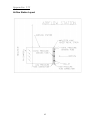
Appendix III ......................................................................................................................... 45
Airflow Station Layout .............................................................................................................. 45
4
Overview
Applied Air’s Digital Control System, AdaptAire, is designed to give the user the ultimate in
heater performance and operational flexibility. Combined with the patent applied for airflow
station used with recirculating heaters, AdaptAire provides flexibility, adaptability, and
reliability in a user-friendly package. Non-recirculating heaters, equipped with the AdaptAire
system, do not have return air capabilities, and all functions related to recirculating heaters
are not relevant. Where a function is similar but different between recirculating and nonrecirculating heaters, the function is explained separately.
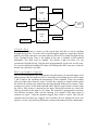
AdaptAire accepts single or multiple heaters on the system network. Each heater is provided
with a local user interface. The operating parameters for individual heaters may be input through
the local interface. A PC may also be connected to the network. This allows the user to configure
each heater separately, or all heaters can be configured simultaneously. A controls contractor can
provide assistance in networking.
Operational modes include time scheduling, filter monitoring, and multiple damper control and
temperature control schemes. All of these modes provide the maximum in heater operational
flexibility.
The patent applied for airflow station imparts unparalleled adaptability into the operation of each
heater. A daily self-calibration enables AdaptAire to detect the total air volume and the exact
ratio of outside and return air entering the heater. Then AdaptAire daily fine-tunes the heater’s
operation based on these new parameters. Air volume can vary because of changes in static
pressure conditions due to loading filters, VAV boxes, and building dynamics. These varying
conditions influence the ventilation air provided by the heater, which in turn impacts the
allowable equivalent temperature rise of the heater. Systems, which do not measure the outside
air/return air ratio and recalibrate themselves accordingly, may cause the burner to shut off when
it is need the most.
AdaptAire diagnostic capabilities insure swift response to abnormal heater conditions. A fault is
generated anytime the operational parameters and actual heater operation are at odds. An
indication of trouble is displayed at the local user interface and system PC in text format. In the
Diagnostics section of this manual is a list of all faults and possible causes and solutions.
All of the features of the AdaptAire system are designed to provide the user with real time
information. At any time the user can display all of the operational parameters, make changes, if
necessary, and observe the various temperature, pressure, and damper readings. The system’s
diagnostic capabilities provide the user with up to the minute status reporting.
5
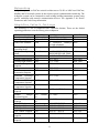
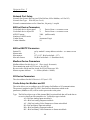
Controller Specifications
OUTPUT ASSIGNMENTS - ANALOG
AO1 Unassigned
AO2 RA or Mixing Damper Control
0 – 10VDC
AO3 Burner firing rate (to Maxitrol A200)
0 – 10 VDC
AO4 User Configured
POWER REQUIREMENTS
24VAC ± 10%, 20VA
NETWORK COMMUNICATION
BACnet, Modbus, or N2 bus at 38.4K or
9600 baud. LonWorks using gateway.
LOCAL USER INTERFACE
BACview 2 line, 16 character display
connected to controller via CAT5 cable and
RJ45 connectors. BACview 4 line, 40
character display required for Modbus, or
N2 bus. Either BACview can be located up
to 1000’ away from the controller.
OUTPUT ASSIGNMENTS - DIGITAL
DO1 Unassigned
DO2 Pilot to Main Flame Sensor
Changeover Switch
DO3 Alarm
DO4 Cooling Enable
DO5 Burner Enable
DO6 Unit Enable
MEMORY
512K bytes of flash memory and 512K
bytes of non-volatile battery-backed
RAM
INPUT ASSIGNMENTS - UNIVERSAL
IN1 Outside Air sensor
IN2 Room Air sensor (no limit on distance
from controller)
IN3 Discharge Air sensor
IN4 Fan Status
IN5 Safety Circuit Status
IN6 Burner Status
IN7 Multiplexed
A) Auxiliary Unit Enable
B) Clogged Filter
IN8 Multiplexed
A) 100% Outside Air Switch
B) Flame Failure from flame
IN9 Pressure Transducer for Building
Pressure Control or User Configured
IN10 Pressure Transducer for Flow Station
REALTIME CLOCK
Battery-backed to keep time in event of
power failure.
TEMPERATURE OPERATING RANGE
-20°F to 150°F, 10% to 95% RH noncondensing
INPUTS/OUTPUTS
10 Universal Inputs
• 0-5 VDC or 0-20 mA
6 Digital Outputs
• Relay contacts rated at 3A Resistive
@ 24VAC
• Hand-Off-Auto switches
• LED indication
4 Analog Outputs
• 0 – 10 VDC or 0 – 20 mA
• LED indication
6
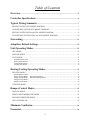
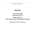
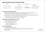
Typical Wiring Schematic
RECIRCULATING CDF MODEL DIAGRAM
7
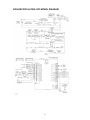
NON-RECIRCULATING CDF MODEL DIAGRAM
8
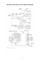
RECIRCULATING DFOA and DFIA MODEL DIAGRAM
9
NON-RECIRCULATING DFOA and DFIA MODEL DIAGRAM
10
Networking
AdaptAire operates on BACnet network architecture at 38.4K or 9600 baud. BACnet,
Modbus and N2 network systems do not require special communication interfacing. The
AdaptAire system can be connected to most existing building automation systems using
special controllers and network communication devices. See Appendix I for Device
Parameters and Cache Setup information.
AdaptAire Default Settings
The following is a list of AdaptAire DDC controller defaults. These are the default
operating parameters set at the factory prior to shipment.
ITEM
Unit Network Address
Unit Operating Mode
Time Clock Schedule
DEFAULT
000 binary dips
OFF
None
Heating/Cooling
Operating Mode
Damper
Operating
Mode
Fuel Selection
Heating Night Setback
Cooling Night Setback
Room
Temperature
Setpoint
Freezestat
Outside
Air
Economizer Setpoint
Minimum Discharge
Temperature Setpoint
Maximum Discharge
Temperature Setpoint
Mixed
Air
Temperature Setpoint
Building
Pressure
Setpoint
Manual
Damper
Position Setpoint
Minimum Ventilation
Setpoint
User PID Select
High Input Value
Low Input Value
User Control Setpoint
Maximum
User
Setpoint
Minimum
User
Setpoint
Heating
Manual
RANGE
000 – 255 binary dips
OFF/MANUAL/AUTO
16 Normal/16 Holiday/8
Override schedules
HEATING/COOLING
RELATED I/O
DO6
DO6
DO5
Natural Gas
55°F
100°F
65°F
MANUAL/BUILDING
PRESS/MIXED AIR TEMP
NATURAL/PROPANE
40°F - 80°F
75°F - 120°F
55°F - 90°F
AO3
DO5, DO6
DO4, DO6
AO2, DO6
45°F
65°F
35°F - 50°F
40°F - 80°F
DO6
DO5
55°F
40°F - 130°F
AO3
100°F
55°F - 130°F
AO3
50°F
30°F - 90°F
AO2
0” W. C.
-0.05” - +0.05” W. C.
IN10, AO2
20%
Outside
Air
20%
Outside
Air
Direct Acting
0.00
0.00
0.00
0.00
0% - 100%
AO2
0% - 100%
AO2
DIRECT/REVERSE
-9999.99 – 9999.99
-9999.99 – 9999.99
-9999.99 – 9999.99
-9999.99 – 9999.99
IN-9,AO1
IN-9
IN-9
IN-9,AO1
IN-9,AO1
0.00
-9999.99 – 9999.99
IN-9,AO1
11
AO2
Unit Operating Modes
There are three different modes which control the supply fan and unit operation: Off,
Manual, and Auto. These operating modes are selected through the UNIT MODES menu
tree of the local user interface or PC.
OFF MODE
Off Mode is the default heater operational mode. To place the unit in Off Mode scroll
through the Unit Modes menu tree, locate the AUTO/OFF/MAN branch, and select OFF.
This will place the unit in the OFF mode. The OFF mode prevents the fan and burner
from starting. This mode will override the Time Clock and Night Setback functions. The
Off mode prevents digital output DO1 from activating and keeps the heater from starting.
MANUAL MODE
Manual Mode allows the supply fan to turn on regardless of the Time Clock or Night
Setback functions. To place the unit in Manual Mode scroll through the Unit Modes
menu tree, locate the AUTO/OFF/MAN branch, and select MANUAL. This will place
the unit in the MANUAL mode. This function activates digital output DO1.
AUTO MODE
Auto Mode has four different functions which control the supply fan and unit operation.
They are a time clock function, heating and cooling night setbacks, and a signal from an
external source to an auxiliary digital input. To place the unit in Auto Mode scroll
through the Unit Modes menu tree, locate the AUTO/OFF/MAN branch, and select
AUTO. This will place the unit in the AUTO mode. This activates the four Auto mode
functions.
Scheduling Time Clock
The primary Auto Mode function is the Time Clock Schedule. The Time Clock function
allows the user to schedule the operational times of the heater. There are three different
schedules available: normal, holiday, and override. Each of these schedules can be
programmed for up to nine separate On/Off events with any combination of days. The
normal schedule sets the typical On/Off times for the heater. The holiday schedule sets
the Off times for holidays and other shutdown periods. The override schedule sets the On
times that will override the holiday schedule. This scheduling system allows the user to
program a diverse array of On/Off operations. An example of a typical schedule would be
to have the heater On Monday through Friday from 6:00 AM to 5:00 PM, except during
the weeks of Thanksgiving and Christmas when the heaters will be Off. However they
will run each weekday during the Thanksgiving shutdown from 8:00 AM until noon
while a maintenance crew is in the building. AdaptAire has no preset operational
schedule. To set the operational times of the heater scroll through the SCHEDULES
menu tree, and locate the desired Normal, Holiday, or Override branch. Enter the days
and times for the heater to operate. In the Normal or Override section these times should
correspond to the desired “on” times for the heater’s operation. In the Holiday section
these times should correspond to the desired “off” times for the heater’s operation.
See the CLOCK SET section of this manual for setting the time, date and Daylight
Savings function.
Heating Night Setback
The Heating Night Setback function automatically cycles the heater “on” if the room
temperature falls below the Heating Night Setback temperature setpoint, and the heater is
12
scheduled to be “off”. If the heater is scheduled to be “off” and the Heating Night
Setback function turns the heater “on”, the heater will be cycled “off” once the room air
temperature has risen 3° above the Heating Night Setback setpoint. This function toggles
digital output DO1. The default for this setpoint is 55°F. To change the Heating Night
Setback setpoint scroll through the SETPOINTS menu tree, locate the Heating Night
Setback setpoint and enter a new temperature. The allowable temperature range is 40°F 80°F.
Cooling Night Setback
The Cooling Night Setback function automatically cycles the heater “on” if the room
temperature rises above the Cooling Night Setback temperature setpoint and the heater is
scheduled to be “off”. If the heater is scheduled to be “off” and the Cooling Night
Setback function turns the heater “on”, the heater will be cycled off once the room air
temperature has fallen 3° below the Cooling Night Setback setpoint. This function
toggles digital output DO1. The default for this setpoint is 100°F. To change the Cooling
Night Setback setpoint scroll through the SETPOINTS menu tree, locate the Cooling
Night Setback setpoint and enter a new temperature. The allowable temperature range is
75°F - 125°F.
Auxiliary Unit Enable
The Auxiliary Unit Enable function overrides all other Auto Mode functions and
automatically cycles the heater into operation. This function is activated whenever a
10,000Ω or 6,667Ω resistance is connected across Universal Input 7. See the Typical
Wiring Schematic and Multiplexed Input sections of this manual for more information.
This function can be used with a twist timer, toggle switch, door switch, exhaust fan
interlock, or any other dry contact to override the time clock schedule.
Heating/Cooling Operating Modes
There are two different modes which control the heating and cooling operation: Heating
and Cooling. These operating modes are selected through the UNIT MODES menu tree of
the local user interface or PC.
HEATING MODE
Heating Mode allows the burner to operate as needed. When heating is required, digital
output DO5 will be activated. To place the unit in Heating Mode scroll through the Unit
Modes menu tree, locate the HTG/CLG/OFF branch, and select Heating. This will place
the unit in the Heating mode.
General Burner Control
In the Heating Mode the burner will modulate to maintain a constant room temperature.
To change the desired heating room temperature scroll through the SETPOINTS menu
tree, locate the Heating Setpoint, and enter a new temperature. The allowable temperature
range is 55°F - 90°F. The burner will modulate using a PID loop to maintain this
temperature. Additionally, the control system modulates the burner to maintain the
supply air temperature within a user defined operating window. This window defines the
maximum and minimum discharge temperatures.
To change the desired minimum supply or discharge air temperature scroll through the
SETPOINTS menu tree, locate the MIN DAT Setpoint, and enter a new temperature.
This temperature must not be greater than the MAX DAT Setpoint. The allowable
temperature range is 40°F - 90°F. This sets the lowest discharge air temperature which
will leave the heater.
13
To change the desired maximum supply or discharge air temperature scroll through the
SETPOINTS menu tree, locate the MAX DAT Setpoint, and enter a new temperature.
This temperature must not be less than the MIN DAT Setpoint. The allowable
temperature range is 55°F - 130°F. This sets the highest discharge air temperature which
will leave the heater.
If the maximum and minimum discharge temperature setpoints are set for the same
temperature, the supply air temperature will be the same as the setpoint regardless of the
room temperature setpoint or actual room temperature.
Direct fired heaters deliver all of their products of combustion directly to the heated air
space. For this reason it is extremely important that the proper ventilation rate be
maintained to dilute these emissions. The AdaptAire system accurately measures the ratio
of outside and return air, calculates the allowable equivalent temperature rise and
automatically limits the burners firing rate. This insures the products of combustion,
delivered to the space by the heater, are held at or below allowable OSHA thresholds.
The outside air percentage is the driving parameter for this function. A greater percentage
of outside air or dilution air enables the heater to generate a higher allowable equivalent
temperature rise.
In order of lowest to greatest priority the burner modulation parameters are: room
temperature, discharge or supply air temperature, and equivalent temperature rise.
There are three Energy Savings modes which could disable the burner.
Energy Savings Mode 1
Recirculating Heaters
Energy Savings Mode 1 will automatically disable the burner if the mixed air temperature
is equal to or greater than the minimum discharge air temperature setpoint, and the room
air temperature is 5°F above the room air temperature setpoint. When the burner is
disabled, digital output DO5 is deactivated. This function is intended to restrain the room
temperature from rising uncontrollably in buildings with internal heat gain. In certain
conditions it may be necessary to readjust the minimum discharge air or room
temperature setpoint upward or adjust the outside/return air ratio to provide a warmer
supply air temperature.
Energy Savings Mode 1
Non-Recirculating Heaters
Energy Savings Mode 1 will automatically disable the burner if the outside air
temperature is equal to or greater than the minimum discharge air temperature setpoint,
and the room air temperature is 5°F above the room air temperature setpoint. When the
burner is disabled, digital output DO5 is deactivated. This function is intended to restrain
the room temperature from rising uncontrollably in buildings with internal heat gain. In
certain conditions it may be necessary to readjust the minimum discharge air or room
temperature setpoint upward or adjust the outside/return air ratio to provide a warmer
supply air temperature.
Energy Savings Mode 2
Energy Savings Mode 2 will automatically disable the burner if the burner’s minimum
firing rate exceeds the allowable equivalent temperature rise. When the burner is
disabled, digital output DO5 is deactivated. This condition is unlikely to occur unless the
burner’s minimum firing rate is misadjusted and set too high, or the inlet air opening is
restricted.
14
Energy Savings Mode 3
Energy Savings Mode 3 will automatically disable the burner if the outside air
temperature is above the Outside Air Economizer setpoint. When the burner is disabled,
digital output DO5 is deactivated. This function is similar to an inlet duct thermostat. The
burner will cycle back on if the supply air temperature drops 3°F below the Outside Air
Economizer setpoint.
To change the desired outside air economizer temperature scroll through the
SETPOINTS menu tree, locate the ECONOMIZER Setpoint, and enter a new
temperature. The default for this setpoint is 65°F. The allowable temperature range is
40°F - 80°F.
COOLING MODE
Cooling Mode allows the cooling to operate as needed. When cooling is required, digital
output DO4 will be activated. To place the unit in Cooling Mode scroll through the Unit
Modes menu tree, locate the HTG/CLG/OFF branch, and select Cooling. This will place
the unit in the Cooling mode. To change the desired cooling operational temperature
scroll through the Setpoints menu tree, locate the Cooling Setpoint, and enter a new
temperature. The allowable temperature range is 55°F - 90°F. The cooling will be
disabled when the room temperature drops 3°F below the Cooling Setpoint.
Damper Control Modes
There are four different modes which control the heater damper operation: Manual,
Mixed Air Temperature, Building Pressure, and 100% Outside Air. Except for the 100%
Outside Air mode, these operating modes are selected through the menu tree of the local
user interface or PC.
MANUAL MODE
Manual Mode is the default damper operational mode. This will set the outside air
damper to a fixed position. To place the damper operation in Manual Mode scroll through
the menu tree, locate the Damper Mode branch and select Manual Pos. Next, scroll
through the menu tree, locate the Setpoints branch, select Man Vent SP, and enter the
desired damper position. The allowable range is 0% to 100%. Any setting below 20%
will cause the burner to automatically cycle off.
MIXED AIR TEMPERATURE MODE
The Mixed Air Temperature mode varies the percentages of outside air and return air to
maintain a constant mixed air temperature. The AdaptAire controller computes the mixed
air temperature using the outside air and return air temperatures and the ratio of their
respective airflows. To place the damper operation in Mixed Air Temperature Mode
scroll through the menu tree, locate the Damper Mode branch and select MA Temp Ctrl.
Next, scroll through the menu tree, locate the Setpoints branch, select Mixed Air SP, and
enter the desired temperature. The allowable range is 30°F - 80°F. Anytime the outside
air drops below 20% the burner will automatically cycle off. See Minimum
Ventilation.
15
BUILDING PRESSURE MODE
The Building Pressure mode varies the percentages of outside air and return air to
maintain a constant pressure within the space. A pressure transducer compares the
pressure outside the space to the pressure inside the space and transmits a corresponding
signal to the AdaptAire controller. The controller compares this signal to the desired
building pressure setpoint and uses a PID loop to modulate the outside air and return air
dampers to maintain the specified building pressure. To place the damper operation in
Building Pressure Mode scroll through the menu tree, locate the Damper Mode branch
and select Bldg Prs Ctrl. Next, scroll through the menu tree, locate the Setpoints branch,
select Bldg Prs SP, and enter the desired pressure. The allowable range is –0.05”wc to
+0.05”wc. Anytime the outside air drops below 20% the burner will automatically
cycle off. See Minimum Ventilation.
100% OUTSIDE AIR
The 100% Outside Air function automatically opens the outside air dampers and closes
the return air dampers. This function is activated whenever a 10,000Ω or 6,667Ω
resistance is connected across Universal Input 8. See the Typical Wiring Schematic and
Multiplexed Input sections of this manual for more information. The 100% Outside Air
function overrides all other damper control functions.
Minimum Ventilation
The Minimum Ventilation function defines the minimum outside air percentage and
automatically prevents the dampers from modulating below this point. This function can
be used in heating or cooling mode. In the heating mode the AdaptAire controller will
attempt to maintain a minimum of 20% outside air by overriding other damper
controls as necessary. Anytime the outside air drops below 20% the burner will
automatically cycle off. To specify the Minimum Ventilation scroll through the menu
tree, locate the Setpoints branch and select Min Vent, and enter the desired outside air
percentage. The allowable range is 0% - 100% outside air.
Freezestat
The Freezestat function automatically cycles the heater off if the supply air temperature
drops below the Freezestat setpoint for 3 continuous minutes. There is an initial 8 minute
delay prior activation on recirculating heaters, and an initial 6 minute delay on nonrecirculating heaters. The Freezestat function prevents digital output DO1 from activating
and keeps the heater from starting. The default for this setpoint is 45°F. To change the
Freezestat setpoint scroll through the menu tree, locate the Setpoints branch, select
Freezestat SP, and enter a new temperature. The allowable temperature range is 35°F 50°F.
Clogged Filter
An optional clogged filter switch is required for this function. The Clogged Filter
function automatically notifies the user of a dirty filter condition. A Clogged Filter
indication will appear on the local user interface. This function is activated whenever a
20,000Ω or 6,667Ω resistance is connected across Universal Input 7. See the Typical
Wiring Schematic and Multiplexed Input sections of this manual for more information.
16
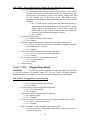
User Configured PID Control
This function is applicable to non-recirculating heaters only. The User Configured PID
Control function allows the user to control an analog output, AO-1, based on a user
defined analog input, IN-9, and setpoint. This function also allows the user to select the
PID type (direct or reverse acting) and establish upper and lower control limits. Five
keypad entries define the operational parameters. These parameters are: User Control
Setpoint, Minimum User Setpoint, Maximum User Setpoint, Low User Input Value, and
High User Input Value. The low and high input values describe the input transducer
range. The control setpoint is the primary operational parameter while the minimum and
maximum setpoints describe the extents of the desired operating range and provide
secondary control as described below. The allowable range for all of these parameters is
–9999.99 - +9999.99.
The analog input must be connected to IN-9. Terminal A on the IN-9 input is the positive
terminal. Terminal B on the IN-9 input is the negative terminal. This input must be
configured for either of two different types of input signals:
0-5Vdc: The output impedance must not exceed 10KΩ. The input impedance of
the controller is 1MΩ.
0-20mA or 4-20mA: The input resistance on the “A” terminal is 250Ω. The “B”
terminal supplies a voltage source to power the transducer. The “B” terminal is
capable of supplying 18-24Vdc, but the total current of all “B” terminals must not
exceed 200mA. If the voltage measured from the “B” terminal to Gnd is less than
18Vdc, an external power supply is required. See the wiring diagrams for
recirculating model heaters for typical connections of transducers.
The IN-9 configuration jumpers on the controller must be set for the
appropriate input signal. A thermistor or RTD must not be used.
The analog output is AO-1 and is 0-10Vdc. Polarity is identified at AO-1 by “Gnd” and
“+”. A contact closure across IN-8 will drive the output to 100%.
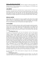
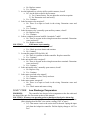
DIRECT ACTING
The controller output AO-1 is modulated by a PID loop from 0% to 100% based on the
User Control setpoint and the input signal to IN-9. As the input signal increases the
output voltage increases. Additionally, a secondary control acts to override the PID loop
to scale the output as follows.
If the input variable equals the User Control setpoint, the output will be determined by
the PID loop. In this situation the override has no effect on the output value.
If the input variable is above the User Control setpoint, the output could increase from
0% to 100% as the input variable increases from the User Control setpoint to the Max
User setpoint. In this situation the output value is the greater of the PID output or the
override output.
If the input variable is below the User Control setpoint, the output could decrease from
100% to 0% as the input variable decreases from the User Control setpoint to the Min
17
User setpoint. In this situation the output value is the lesser of the PID output or the
override output. See the following example.
Assume the user wishes to control a chilled water valve using a temperature transducer.
The control variable will be supply air temperature. As the supply air temperature
increases, the chilled water valve should open to lower the temperature. The temperature
transducer has a range of 50ºF - 85ºF. The user would like the supply air temperature to
be 75ºF but does not want it to drop below 70ºF or go above 80ºF. The parameters
entered on the keypad display will be:
PID Select
High Input Val
Low Input Val
User Ctrl SP
Max User SP
Min User SP
Direct (as input increases output increases)
85ºF
50ºF
75ºF
80ºF
70ºF
The temperature transducer senses the supply air temperature and sends a corresponding
signal to the AdaptAire controller. The controller compares this signal to the desired user
control setpoint (75ºF) and uses the PID loop to modulate the output from 0-100% (010Vdc). The output is connected to the chilled water valve which opens or closes to
maintain the specified supply air temperature.
If the supply air temperature is 75ºF, the output from the controller will be determined by
the PID control sequence, and the override will have no effect on the output.
If the supply air temperature is more than 75ºF, the output from the controller will be
determined by the PID control sequence or the override whichever is less.
If the supply air temperature is less than 75ºF, the output from the controller will be
determined by the PID control sequence or the override whichever is more.
Max User SP
80ºF
100%
Input > 75ºF?
override
scaler
75ºF
User Ctrl SP
0%
>
=
<
75ºF PID 0-100%
75ºF
100%
override
scaler
Min User SP
70ºF
Input < 75ºF?
0%
18
0-100%
Output
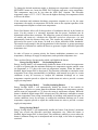
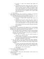
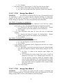
REVERSE ACTING
The controller output AO-1 is modulated by a PID loop from 0% to 100% based on the
User Control setpoint and the input signal to IN-9. As the input signal increases the
output voltage decreases. Additionally, a secondary control acts to override the PID loop
to scale the output as follows.
If the input variable equals the User Control setpoint, the output will be determined by
the PID loop. In this situation the override has no effect on the output value.
If the input variable is above the User Control setpoint, the output could decrease from
100% to 0% as the input variable increases from the User Control setpoint to the Max
User setpoint. In this situation the output value is the lesser of the PID output or the
override output.
If the input variable is below the User Control setpoint, the output could increase from
0% to 100% as the input variable decreases from the User Control setpoint to the Min
User setpoint. In this situation the output value is the greater of the PID output or the
override output. See the following example.
Assume the user wishes to control the fan speed using a variable frequency drive (VFD).
The VFD input is 0-10Vdc. The control variable will be building pressure. As the
building pressure increases, the fan speed should decrease. The building pressure
transducer has a range of –0.1” to +0.1”. The user would like the building pressure to be
+0.03” but does not want it to drop below 0.0” or go above +0.05”. The parameters
entered on the keypad display will be:
PID Select
High Input Val
Low Input Val
User Ctrl SP
Max User SP
Min User SP
Reverse (as input increases output decreases)
0.10
-0.10
0.03
0.05
0.00
The pressure transducer compares the pressure outside the space to the pressure inside the
space and transmits a corresponding signal to the AdaptAire controller. The controller
compares this signal to the desired user control setpoint (0.03”) and uses the PID loop to
modulate the output from 0-100% (0-10Vdc). The output is connected to the VFD which
changes speed to maintain the specified building pressure.
If the building pressure is 0.03”, the output from the controller will be determined by the
PID control sequence, and the override will have no effect on the output.
If the building pressure is more than 0.03”, the output from the controller will be
determined by the PID control sequence or the override whichever is less.
If the building pressure is less than 0.03”, the output from the controller will be
determined by the PID control sequence or the override whichever is more.
19
Max User SP
.05”
0%
Input > .03”?
override
scaler
.03”
User Ctrl SP
100%
>
=
<
.03” PID 0-100%
.03”
0%
override
scaler
Min User SP
.00”
0-100%
Output
Input < .03”?
100%
Clock Set
The Clock Set function is used to set the current time and date as well as enabling
Daylight Saving Time. To set the clock scroll through the menu tree, locate the Clockset
branch, select Date, and enter a new date and time. Select DST to enable Daylight Saving
Time. Daylight Saving Time is the default. If the unit is installed in the southern
hemisphere, Sou Hem must be enabled. The default is not Sou Hem. For you
convenience Daylight Saving Time has been preprogrammed for the next several years.
To reset the starting and ending DST dates scroll through the DST menu tree, locate the
desired year, and enter a new date.
Multiplexed Inputs
The I/O 6104 Automated Logic controller has 6 digital outputs, 10 universal inputs, and 4
analog outputs, thus, the name I/O 6104. Connecting two switching devices each to input
7 and to input 8 has expanded the functionality of this controller. These two switches
effectively share their respective input. To allow the controller to identify which switch
has closed, the switches are connected to the input through different size resistors. These
resistors have values of 10K ohms and 20K ohms. When a single switch is closed, either
the 10K or 20K resistor is connected to the input. When both switches are closed, the
effective resistance at the input is 6,667 ohms. The controller is programmed to associate
each different resistance with a specific function. For example a 20K ohm resistor is
connected to input 7 when the optional clogged filter switch is closed. This tells the
controller that the filters are clogged, and it notifies the user through the local user
interface. See the Typical Wiring Schematic section of this manual for more information.
20
Resets
This section should assist the user in resetting alarms and cycle counters which have been
displayed on the local user interface.
ALARM RS
Alarm RS is the alarm reset. To reset an alarm scroll through the menu tree, locate the
Resets branch and select Alarm RS. Press the Enter key. The word OFF should flash.
Now press the INC key and the word ON should flash on the display. Press the Enter key
again and ON should stop flashing. Repeat this process so the word OFF is displayed and
not flashing. The alarm has now been cleared and the Alarm RS function has been
rearmed.
CALIBRATE
The Calibrate function forces the controller to recalibrate the return air flow station. The
recalibration will occur immediately if the fan is running or at the next fan start. To
recalibrate scroll through the menu tree, locate the Resets branch and select Calibrate.
Press the Enter key. The word OFF should flash. Now press the INC key and the word
ON should flash on the display. Press the Enter key again and ON should stop flashing.
Repeat this process so the word OFF is displayed and not flashing. The calibration has
now been initiated and the Calibration function has been rearmed.
FAN COUNT
Fan Count records each fan start. To reset a fan count scroll through the menu tree, locate
the Resets branch and select Fan Count. Press the Enter key. The word OFF should flash.
Now press the INC key and the word ON should flash on the display. Press the Enter key
again and ON should stop flashing. Repeat this process so the word OFF is displayed and
not flashing. The fan count has now been cleared and the Fan Count function has been
rearmed.
HEATING COUNT
Heating Count records each burner start. To reset a heating count scroll through the menu
tree, locate the Resets branch and select Heating Count. Press the Enter key. The word
OFF should flash. Now press the INC key and the word ON should flash on the display.
Press the Enter key again and ON should stop flashing. Repeat this process so the word
OFF is displayed and not flashing. The heating count has now been cleared and the
Heating Count function has been rearmed.
COOLING COUNT
Cooling Count records each cooling start. To reset a cooling count scroll through the
menu tree, locate the Resets branch and select Cooling Count. Press the Enter key. The
word OFF should flash. Now press the INC key and the word ON should flash on the
display. Press the Enter key again and ON should stop flashing. Repeat this process so
the word OFF is displayed and not flashing. The cooling count has now been cleared and
the Cooling Count function has been rearmed.
Diagnostics – Critical Fault Codes
This section should assist the user in troubleshooting critical fault codes messages which
have been displayed on the local user interface.
21
FAULT CODE:
Unit off/Fan on
PROBLEM:
The controller has not activated DO6 to start the fan, but the fan
status input, IN4, is receiving a signal that the fan is running.
SOLUTION:
If fan is running
1. Is controller output LED for DO-6 lit?
a. Yes. There is a problem with the controller program. Call factory.
b. No. Continue.
2. Is controller output contact for DO-6 closed?
a. Yes. Turn off the power to the controller and recheck. If contact is still
closed the controller output is shorted. Replace the controller.
b. No. Continue.
3. Is the unit enable relay energized?
a. Yes. There is a short or jumper in the wiring. Determine cause and
rectify.
b. No. Continue.
4. Is motor starter energized?
a. Yes. There is a short or jumper in the wiring. Determine cause and
rectify.
b. No. Continue.
5. Is the fan status relay energized?
a. Yes. There is a short or jumper in the wiring. Determine cause and
rectify.
b. No. Continue.
6. Is the fan status relay’s normally open contact, closed?
a. Yes. Replace relay.
b. No. Continue.
7. Is there continuity between both IN-4 terminals 7 and 8?
a. Yes. There is a short in the wiring between these terminals. Determine
cause and rectify.
b. No. Replace controller.
SOLUTION:
If fan is not running
1. Is the fan status relay’s normally open contact, closed?
a. Yes. Replace relay.
b. No. Continue.
2. Is there approximately 5VDC at both IN-4 terminals 7 and 8?
a. Yes. There is a short in the wiring between these terminals. Determine
cause and rectify.
b. No. Replace controller.
FAULT CODE:
Unit on/Fan off
PROBLEM:
The controller has activated DO6 to start the fan, but the fan status
input, IN4, is not receiving a signal that the fan is running.
SOLUTION:
If fan/motor is running
1. Is the BACview remote indicating an alarm?
a. Yes. Check previous alarms and continue.
b. No. Continue.
2. Is the motor starter’s normally open auxiliary contact, closed?
22
a. No. Replace contact.
b. Yes. Continue.
3. Are the high and low velocity airflow switch contacts, closed?
a. No. Are the belts on and is the fan motor.
1) Yes. Contact factory. Do not adjust the switches setpoints.
2) No. Determine cause and rectify.
b. Yes. Continue.
4. Is the fan status relay energized?
a. No. There is an open or break in the wiring. Determine cause and
rectify.
b. Yes. Continue.
5. Is the fan status relay’s normally open auxiliary contact, closed?
a. No. Replace relay.
b. Yes. Continue.
6. Is there continuity between both IN-4 terminals 7 and 8?
a. No. There is an open in the wiring between these terminals. Determine
cause and rectify.
b. Yes. Replace controller.
SOLUTION:
If fan/motor is not running
1. Is the BACview remote indicating an alarm?
a. Yes. Check previous alarms and continue.
b. No. Continue.
2. Is controller output LED for DO-6 lit?
a. No. There is a problem with the controller. Replace controller.
b. Yes. Continue.
3. Is the unit enable relay energized?
a. No. There is an open in the wiring between these terminals. Determine
cause and rectify.
b. Yes. Continue.
4. Is the unit enable relay’s normally open contact, closed?
a. No. Replace relay.
b. Yes. Continue.
5. Is the motor overload relay tripped?
a. Yes. Determine cause, rectify and reset.
b. No. Continue.
6. Is the motor starter energized?
a. No. There is an open or break in the wiring. Determine cause and
rectify.
b. Yes. Check motor and motor wiring.
FAULT CODE:
Low Discharge Temperature
PROBLEM:
The controller has detected a low temperature at the fan outlet and
has shut off the unit. See Freezestat section of this manual.
SOLUTION: If burner was operating prior to shutdown (check prior alarm log)
1. Is the outside air (OAt), room air (RoomT), or discharge air temperature
(DAt), displayed on the BACview remote, reading 150°F or more?
a. Yes. That sensor circuit or the sensor itself is shorted. Unplug the input
jack from the AdaptAire controller. Did the display change to -40°F or
less?
23
2.
3.
4.
5.
1) No. There is a short in the controller input. Replace the
controller.
2) Yes. Disconnect the sensor wiring at the sensor. Connect an
ohmmeter to the sensor. If it is shorted replace the sensor. At
70°F the resistance should be 10KΩ. See thermistor output
curve for other temperatures. If it is not shorted, there is a short
in the wiring between the sensor and the input plug. Determine
cause and rectify. Refer to Appendix II for a typical 10KΩ
thermistor output curve.
b. No. Continue.
Is the outside air (OAt), room air (RoomT), or discharge air temperature
(DAt), displayed on the BACview remote, reading -40°F or less?
a. Yes. That sensor circuit or the sensor itself is open. Jumper the input
for the sensor. Did the display change to 150°F or more?
1) No. There is an open in the controller input. Replace the
controller.
2) Yes. Disconnect the sensor wiring at the sensor. Connect an
ohmmeter to the sensor. If it is open replace the sensor. At
70°F the resistance should be 10KΩ. See thermistor output
curve for other temperatures. If it is not open, there is a break
in the wiring between the sensor and the input plug. Determine
cause and rectify.
b. No. Continue
Reset the alarm. Check and note the DC voltage at AO-3. Set the Heating
Setpoint for 90°F. Set the MAX DAT and MIN DAT Setpoints for 130°F. Did
the Burner VDC, displayed on the BACview remote, increase??
a. No. Unless the outside air temperature is extremely warm the Burner
VDC should have increased to 7.5VDC or more. Close the manual
main gas valve closest to the burner and measure the discharge air
temperature. Is it less than 130°F?
1) Yes. There is a problem with the controller program or
controller itself. Contact the factory.
2) No. The outside air temperature is too hot to determine the
actual cause of the problem. Reset the alarm and recheck when
the outside air temperature is much cooler.
b. Yes. This signal is fed to the Maxitrol A200 signal conditioner.
Disconnect the wires from terminals 5 and 6 on the A200 and measure
the voltage on the wires. Is it the same as the voltage coming from the
controller?
1) No. There is an open in the wiring from the controller output.
Correct wiring and reconnect the wires to the terminals on the
A200. Be sure the wire from AO-3 terminal number 6 is
connected to the A200’s terminal number 5.
2) Yes. Continue.
Is there 24VAC on the A200 terminals 1 and 2?
a. No. Determine cause and rectify.
b. Yes. Continue.
Is there twice the DC voltage on the A200 terminals 3 and 4 as there is on
terminals 5 and 6?
a. No. Replace the A200.
b. Yes. Continue.
24
c. Yes. Continue.
6. Is the DC voltage on the Maxitrol modulating valve terminals the same as the
DC voltage on the A200 terminals 3 and 4?
a. No. There is a break in the wiring between the A200 and the
modulating valve terminals. Determine cause and rectify.
b. Yes. The electronics are working to this point. Continue.
7. Is there sufficient temperature rise for the amount of outside air that is being
delivered to the space?
a. No. Follow the instructions in this manual for placing the heater in
Manual Pos. damper control. Adjust the Man. Vent setpoint to 20%
outside air. Is there sufficient temperature rise for the amount of
outside air that is being delivered to the space?
1) No. Contact the factory.
2) Yes. Continue.
b. Yes. Continue.
8. Verify there is sufficient inlet gas pressure. Verify the modulating valve is
properly adjusted. Verify the burner orifices are clear of obstruction. Contact
the factory.
SOLUTION: If burner was not operating prior to shutdown (check prior alarm log)
1. Is there a prior alarm such as Safety Ckt., Airflow Sw., or Flame Failure?
a. Yes. See the Diagnostic section for the previous alarm.
b. No. Continue.
2. Is the room air (RoomT) or discharge air temperature (DAt), displayed on the
BACview remote, reading 150°F or more?
a. Yes. That sensor circuit or the sensor itself is shorted. Unplug the input
jack from the AdaptAire controller. Did the display change to -40°F or
less?
1) No. There is a short in the controller input. Replace the
controller.
2) Yes. Disconnect the sensor wiring at the sensor. Connect an
ohmmeter to the sensor. If it is shorted replace the sensor. At
70°F the resistance should be 10KΩ. See thermistor output
curve for other temperatures. If it is not shorted, there is a short
in the wiring between the sensor and the input plug. Determine
cause and rectify. Refer to Appendix II for a typical 10KΩ
thermistor output curve.
b. No. Continue.
3. Is the discharge air temperature (DAt), displayed on the BACview remote,
reading -40°F or less?
a. Yes. The discharge air temperature sensor circuit or the sensor itself is
open. Jumper the input for the sensor. Did the display change to 150°F
or more?
1) No. There is an open in the controller input. Replace the
controller.
2) Yes. Disconnect the discharge air temperature sensor wiring at
the sensor. Connect an ohmmeter to the sensor. If it is open
replace the sensor. At 70°F the resistance should be 10KΩ. See
thermistor output curve for other temperatures. If it is not open,
there is a break in the wiring between the sensor and the input
plug. Determine cause and rectify.
b. No. Continue
25
4. Reset the alarm. Check and note the DC voltage at AO-3. Set the Heating
Setpoint for 90°F. Set the MAX DAT and MIN DAT Setpoints for 130°F. Did
the Burner VDC, displayed on the BACview remote, increase??
a. No. Unless the outside air temperature is extremely warm the Burner
VDC should have increased to 7.5VDC or more. Close the manual
main gas valve closest to the burner and measure the discharge air
temperature. Is it less than 130°F?
1) Yes. There is a problem with the controller program or
controller itself. Contact the factory.
2) No. The outside air temperature is too hot to determine the
actual cause of the problem. Reset the alarm and recheck when
the outside air temperature is much cooler.
b. Yes. This signal is fed to the Maxitrol A200 signal conditioner.
Disconnect the wires from terminals 5 and 6 on the A200 and measure
the voltage on the wires. Is it the same as the voltage coming from the
controller?
1) No. There is an open in the wiring from the controller output.
Correct wiring and reconnect the wires to the terminals on the
A200. Be sure the wire from AO-3 terminal number 6 is
connected to the A200’s terminal number 5.
2) Yes. Continue.
5. Is there 24VAC on the A200 terminals 1 and 2?
a. No. Determine cause and rectify.
b. Yes. Continue.
6. Is there twice the DC voltage on the A200 terminals 3 and 4 as there is on
terminals 5 and 6?
a. No. Replace the A200.
b. Yes. Continue.
c. Yes. Continue.
7. Is the DC voltage on the Maxitrol modulating valve terminals the same as the
DC voltage on the A200 terminals 3 and 4?
a. No. There is a break in the wiring between the A200 and the
modulating valve terminals. Determine cause and rectify.
b. Yes. The electronics are working to this point. Continue.
8. Is there sufficient temperature rise for the amount of outside air that is being
delivered to the space?
a. No. Follow the instructions in this manual for placing the heater in
Manual Pos. damper control. Adjust the Man. Vent setpoint to 20%
outside air. Is there sufficient temperature rise for the amount of
outside air that is being delivered to the space?
1) No. Contact the factory.
2) Yes. Continue.
b. Yes. Continue.
9. Verify there is sufficient inlet gas pressure. Verify the modulating valve is
properly adjusted. Verify the burner orifices are clear of obstruction. Contact
the factory.
FAULT CODE:
Safety Circuit Open
PROBLEM:
circuit.
The controller has detected a failure in the safety
26
SOLUTION: If fan is not running (check prior alarm log)
1. Is there a prior alarm such as Unit On/Fan Off or Airflow Sw?
a. Yes. See the Diagnostic section for the previous alarm.
b. No. Continue.
2. Set Unit Mode to Manual. Did fan start?
a. No. See the Diagnostic section for Unit On/Fan Off.
b. Yes. Continue.
SOLUTION: If fan is running (check prior alarm log)
1. Is the high temperature limit tripped?
a. Yes. Determine cause and rectify.
b. No. Continue.
2. Is the low gas pressure switch closed?
a. No. Verify the inlet gas pressure is as specified on the gas piping
diagram. The low gas pressure switch setpoint should not be
adjusted. The inlet gas pressure must remain as specified when unit
fires at full input. Correct gas pressure and reset switch. If the switch
cannot be reset, replace it. See Installation, Operation and Owners
Manual for more information.
b. Yes. Continue.
3. Is the high gas pressure switch closed?
a. No. Verify the firing rate pressure at full input is as specified on the
unit rating plate. The high gas pressure switch setpoint should not
be adjusted. The firing rate pressure must remain as specified when
unit fires at full input. Correct gas pressure and reset switch. If the
switch cannot be reset, replace it. See Installation, Operation and
Maintenance Manual for more information.
b. Yes. Continue.
4. Is the safety circuit relay energized?
a. No. Check for loose wiring and rectify.
b. Yes. Continue.
5. Is the safety circuit relay’s normally open contact closed?
a. No. Replace the relay.
b. Yes. Continue.
8. Is there continuity across both IN-5 terminals 9 and 10?
a. No. There is an open in the wiring between these terminals. Determine
cause and rectify.
b. Yes. Replace controller.
FAULT CODE:
Burner Status
PROBLEM:
The controller has activated DO5 to start the burner, but
the burner status input, IN6, is not receiving a signal that the burner is on.
SOLUTION:
Inspect burner control circuit and burner
1. Is there a prior alarm such as Unit On/Fan Off, Airflow Sw., or Safety
Circuit?
a. Yes. See the Diagnostic section for the previous alarm.
b. No. Continue.
2. Is the burner enable relay energized?
a. No. There is an open in the 24VAC circuit. Determine
cause and rectify.
27
3.
4.
5.
6.
7.
8.
b. Yes. Continue.
Is the burner enable relay’s normally open contact closed?
a. No. Replace relay.
b. Yes. Continue.
Is there a pilot flame present?
a. No. Refer to the Installation, Operation and Maintenance
Manual for guidance in troubleshooting the flame relay or
ignition module.
b. Yes. Continue.
Is the flame relay or ignition module main valve terminal
energized?
a. No. Refer to the Installation, Operation and Maintenance
Manual for guidance in troubleshooting the flame relay or
ignition module.
b. Yes. Continue.
Is the gas valve/burner status relay energized?
a. No. There is an open in the main valve control circuit.
Determine cause and rectify.
b. Yes. Continue.
Is the gas valve/burner status relay’s normally open contact
closed?
a. No. Replace relay.
b. Yes. Continue.
Is there continuity across both IN-6 terminals 11 and 12?
a. No. There is an open in the wiring between these terminals. Determine
cause and rectify.
b. Yes. Replace controller.
FAULT CODE:
Burner Hand
PROBLEM:
The controller has not activated DO-5 to start the
burner, but the burner status input, IN6, is receiving a signal that the burner is
on.
SOLUTION:
Inspect burner control circuit. This fault has the potential to be
a very serious problem. Close the manual gas valves immediately if the fan is not
running.
1. Is the controller output DO-5 LED lit?
a. Yes. Close manual gas valves. There is a problem with the
controller program. Contact factory.
b. No. Continue.
2. Are the main automatic gas shutoff valves energized?
a. No. The main automatic gas shutoff valves are leaking.
Turn off unit and close manual gas valves. Determine cause
of valve failure and rectify.
b. Yes. Continue.
3. Is the flame relay energized?
a. No. There is a short in the wiring of the gas valves. Close
manual gas valves. Determine cause of short and rectify.
b. Yes. Continue.
4. Is the burner enable relay energized?
28
a. Yes. There is a short in the wiring of the flame relay. Close
manual gas valves. Determine cause of short and rectify.
b. No. Continue.
5. Is the burner enable relay’s normally open contact closed?
a. Yes. Close manual gas valves. Replace the relay.
b. No. Continue.
6. Unplug the input terminals from the input jack. Is there continuity
between IN-6 terminals 11 and 12
a. No. Close manual gas valves. There is a short in the wiring
between the burner status relay and IN-6. Determine cause
and rectify.
b. Yes. Close manual gas valves. Replace the controller.
FAULT CODE:
Flame Failure
PROBLEM:
DFOA and DFIA Models Only. The controller has
received a signal from the flame relay at input, IN8, indicating a flame failure.
SOLUTION:
Investigate flame relay
1. Is there a prior alarm such as Unit On/Fan Off, Airflow Sw., or Safety
Circuit?
a. Yes. See the Diagnostic section for the previous alarm.
b. No. Continue.
2. See flame relay troubleshooting information in unit Installation,
Operation, and Maintenance Manual.
Diagnostics – Non-Critical Fault Codes
This section should assist the user in troubleshooting non-critical fault codes messages
which have been displayed on the local user interface.
FAULT CODE:
Check Airflow Switches
PROBLEM:
The controller has activated DO6 to start the fan, and detected that
the fan is running from a signal at the fan status input, IN4. Subsequently, the controller
has detected a momentary opening of the fan status input, IN4. The momentary opening
must occur within two seconds of the previous closure for this fault to occur.
SOLUTION: If high airflow switch is opening. Do not adjust the switch setpoints
1. Are all of the filters in place?
a. No. Install filters and continue.
b. Yes. Continue.
2. Does the external static pressure match that listed on the rating plate?
a. No. Verify all associated ductwork is installed and continue.
b. Yes. Continue.
3. Does the fan RPM match that listed on the Spec. Sheet?
a. No. Correct to reduced fan speed and continue.
b. Yes. Continue.
4. Are the airflow switches’ sensing tubes obstructed?
a. Yes. Clear and continue.
b. No. Continue.
5. Contact factory.
29
SOLUTION: If low airflow switch is opening. Do not adjust the switch setpoints
1. Does low airflow switch open when the burner is off
a. No. Disconnect both pressure sensing tubes from one of the airflow
switches and measure the differential pressure by connecting the high
sensing port of a manometer to one of the airflow sensing tubes and
the low sensing port to the other. Is the differential pressure
approximately the midpoint between the high and low airflow switch
setpoints?
1) No. Close the profile opening until the differential pressure is
approximately the midpoint between the high and low airflow
switch setpoints. Reconnect the sensing tubes, restart the
burner, and verify the airflow switch remains closed when the
burner is at the maximum rated input. Continue.
2) Yes. Continue.
2. Are all of the filters dirty?
a. Yes. Install clean filters and continue.
b. No. Continue.
3. Does the external static pressure match that listed on the rating plate?
a. No. Verify all associated ductwork is installed as designed, and there
are no obstructions. Continue.
b. Yes. Continue.
4. Does the fan RPM match that listed on the Spec. Sheet?
a. No. Correct to increased fan speed and continue.
b. Yes. Continue.
5. Are the airflow switches’ sensing tubes obstructed?
a. Yes. Clear and continue.
b. No. Continue.
6. Contact factory.
FAULT CODE:
Clogged Filter Switch
PROBLEM:
The filter air pressure switch has closed and connected a 20,000Ω
or 6,667Ω resistance at controller input IN7. See the Typical Wiring Schematic,
Multiplexed Input, and Clogged Filter sections of this manual for more information.
SOLUTION: If clogged filter switch is closing.
1. Are the filters dirty?
a. Yes. Install clean filters and continue.
b. No. Continue.
2. Are the airflow switch sensing tubes obstructed?
a. Yes. Clear and continue.
b. No. Continue.
3. Is the airflow switch setpoint properly adjusted?
a. No. Adjust setpoint.
b. Yes. Continue.
4. Are the wires connected to the air pressure switch’s normally open contact?
a. No. Rewire switch and continue.
b. Yes. Continue.
5. Is the air pressure switch’s normally open contact open?
a. No. Disconnect the sensing tubes and recheck. Replace the switch if
contacts do not open.
30
b. Yes. Continue.
6. Disconnect the wire from terminal 13 of IN7 Does this clear the alarm?
a. Yes. There is short in the wiring. Determine cause and rectify.
b. No. There is an internal short in the controller. Replace the controller.
FAULT CODE:
Energy Save Mode 1
PROBLEM:
The controller has turned off DO5 because it determined the mixed
air temperature is equal to or greater than the minimum discharge air temperature
setpoint, and the room air temperature is 5°F above the room air temperature setpoint.
See the Energy Savings Mode 1 section of this manual for more information.
SOLUTION: If setpoints are misadjusted
1. Is the mixed air temperature (MAt), displayed on the BACview remote,
greater than or equal to the minimum discharge air temperature setpoint?
a. Yes. Increase the MIN DAT setpoint. See Heating Mode – General
Burner Control section of this manual for more information.
b. No. Continue.
2. Is the room temperature more than 5°F above the room air temperature
setpoint?
a. Yes. Increase the Roomt SP setpoint. See Heating Mode – General
Burner Control section of this manual for more information.
b. No. Continue.
SOLUTION: If setpoints are not misadjusted
1. Is there a prior alarm such as Insufficient OA?
a. Yes. See the Diagnostic section for the previous alarm.
b. No. Continue.
2. Is the discharge air temperature (DAT), displayed on the BACview remote,
reading 150°F or more?
a. Yes. That sensor circuit or the sensor itself is shorted. Unplug the input
jack from the AdaptAire controller. Did the display change to -40°F or
less?
1) No. There is a short in the controller input. Replace the
controller.
2) Yes. Disconnect the sensor wiring at the sensor. Connect an
ohmmeter to the sensor. If it is shorted replace the sensor. At
70°F the resistance should be 10KΩ. See thermistor output
curve for other temperatures. If it is not shorted, there is a short
in the wiring between the sensor and the input plug. Determine
cause and rectify. Refer to Appendix II for a typical 10KΩ
thermistor output curve.
b. No. Contact factory.
FAULT CODE:
Energy Save Mode 2
PROBLEM:
The controller has turned off DO5 because it determined the
burner’s minimum firing rate exceeds the allowable equivalent temperature rise. See the
Energy Savings Mode 2 section of this manual for more information.
31
SOLUTION: If OAT, RoomT or DAT are such that heat is required
1. Are the outside air hood filters or bird screen or any associated outside air
ductwork obstructed?
a. Yes. Clear obstruction or change filters.
b. No. Continue.
2. Are the outside air and return air dampers and actuators working properly?
a. Yes. Continue.
b. No. Make necessary adjustments and force the unit to recalibrate. See
Calibrate in the Resets Section of this manual.
3. Are the AdaptAire flow measuring station pitot tubes and pressure tubing
clear?
a. Yes. Continue.
b. No. Clean and force the unit to recalibrate. See Calibrate in the Resets
Section of this manual.
4. Do the dampers track with a change in the %OA setpoint? The dampers
utilized on the heater are not linear with respect to airflow and openness, and
as such, the proportion of outside air damper movement will not be exactly
equal to the %OA setpoint. However, at 20% OA the dampers should be
approximately ½” open.
a. Yes. Continue.
b. No. Check the damper motor and linkage connections. When 24VAC
is powering the damper actuator and the control signal is 0VDC, the
outside air damper should be close to a “rattle tight” position and the
return air damper should be open. If the 24VAC power is removed, the
actuator will draw the outside air damper tightly closed and the return
air damper tightly open. When 24VAC is powering the damper
actuator and the control signal is 10VDC, the outside air damper
should be fully open and the return air damper should be closed.
1)
c. No. Contact factory.
5. Do the dampers track with a change in the %OA setpoint? The dampers
utilized on the heater are not linear with respect to airflow and openness, and
as such, the proportion of outside air damper movement will not be exactly
equal to the %OA setpoint. However, at 20% OA the dampers should be
approximately ½” open.
a. Yes. Continue.
b. No. Check the damper motor and linkage connections. When 24VAC
is powering the damper actuator and the control signal is 0VDC, the
outside air damper should be close to a “rattle tight” position and the
return air damper should be open. If the 24VAC power is removed, the
actuator will draw the outside air damper tightly closed and the return
air damper tightly open. When 24VAC is powering the damper
actuator and the control signal is 10VDC, the outside air damper
should be fully open and the return air damper should be closed.
6. Is there approximately 24VAC at the COM and EXC terminals on the airflow
station pressure transducer?
a. Yes. Continue.
b. No. Is there 120VAC on the primary side of the low voltage
transformer and 24VAC volt at the transformer secondary?
1) Yes. There is an open in the wiring between the transformer
and the transducer. Locate the wiring problem and rectify.
32
2) No. If there is 120VAC on the primary and 0VAC on the
secondary, replace the transformer. If there is 0VAC on the
primary, there is an open in the wiring supplying power to the
transformer. Locate the wiring problem and rectify.
7. Remove both of the plastic tubes from the airflow station pressure transducer
and gently blow into the HIGH side port. Is there approximately 5VDC across
the COM and OUT terminals of the pressure transducer?
a. Yes. Continue.
b. No. The pressure transducer is defective. Replace it.
8. Remove both of the plastic tubes from the airflow station pressure transducer
and gently blow into the HIGH side port. Is there approximately 5VDC across
the IN-9 terminals 17 and 18 terminals?
a. Yes. There is a problem with the controller. Replace it.
b. No. There is an open in the wiring between these pressure transducer
and the AdaptAire controller terminals. Locate and rectify.
FAULT CODE:
Energy Save Mode 3
PROBLEM:
The controller has turned off DO5 because it determined the inlet
air temperature exceeds the Economizer setpoint. See the Energy Savings Mode 3 section
of this manual for more information.
SOLUTION: If OAT, RoomT or DAT are such that heat is required
1. Is the outside air temperature (OAT), displayed on the BACview remote,
reading 150°F or more?
a. Yes. The outside air sensor circuit or the sensor itself is shorted.
Unplug the input jack from the AdaptAire controller. Did the display
change to -40°F or less?
1) No. There is a short in the controller input. Replace the
controller.
b. Yes. Disconnect the sensor wiring at the sensor. Connect an ohmmeter
to the sensor. If it is shorted replace the sensor. At 70°F the resistance
should be 10KΩ. See thermistor output curve for other temperatures. If
it is not shorted, there is a short in the wiring between the sensor and
the input plug. Determine cause and rectify. Refer to Appendix II for a
typical 10KΩ thermistor output curve.
2. Is the outside air sensor in the direct sunlight?
a. Yes. Provide shade for the sensor so it is not affected by the direct sun.
b. No. Contact factory.
SOLUTION: If setpoints are misadjusted
1. Is the Econmzr Setpoint set for 80°F?
a. Yes. The outside air temperature is over 80°F and there should be no
need for heat. If this is not the case, contact factory.
b. No. Increase the ECONMZR SP setpoint. See Heating Mode – Energy
Savings Mode 3 section of this manual for more information.
FAULT CODE:
Insufficient OA
PROBLEM:
The controller has turned off DO5 because the percentage of
outside air has dropped below 20% for more than five minutes, and the unit is in the
Heating mode.
33
SOLUTION: If heat is desired
1. Are the outside air hood filters or bird screen or any associated outside air
ductwork obstructed?
a. Yes. Clear obstruction or change filters.
b. No. Continue.
2. Are the outside air and return air dampers and actuators working properly?
a. Yes. Continue.
b. No. Make necessary adjustments and force the unit to recalibrate. See
Calibrate in the Resets Section of this manual.
3. Are the AdaptAire flow measuring station pitot tubes and pressure tubing
clear?
a. Yes. Continue.
b. No. Clean and force the unit to recalibrate. See Calibrate in the Resets
Section of this manual.
4. Do the dampers track with a change in the %OA setpoint? The dampers
utilized on the heater are not linear with respect to airflow and openness, and
as such, the proportion of outside air damper movement will not be exactly
equal to the %OA setpoint. However, at 20% OA the dampers should be
approximately ½” open.
a. Yes. Continue.
b. No. Check the damper motor and linkage connections. When 24VAC
is powering the damper actuator and the control signal is 0VDC, the
outside air damper should be close to a “rattle tight” position and the
return air damper should be open. If the 24VAC power is removed, the
actuator will draw the outside air damper tightly closed and the return
air damper tightly open. When 24VAC is powering the damper
actuator and the control signal is 10VDC, the outside air damper
should be fully open and the return air damper should be closed.
5. Is there approximately 24VAC at the COM and EXC terminals on the airflow
station pressure transducer?
a. Yes. Continue.
b. No. Is there 120VAC on the primary side of the low voltage
transformer and 24VAC volt at the transformer secondary?
1) Yes. There is an open in the wiring between the transformer
and the transducer. Locate the wiring problem and rectify.
2) No. If there is 120VAC on the primary and 0VAC on the
secondary, replace the transformer. If there is 0VAC on the
primary, there is an open in the wiring supplying power to the
transformer. Locate the wiring problem and rectify.
6. Remove both of the plastic tubes from the airflow station pressure transducer
and gently blow into the HIGH side port. Is there approximately 5VDC across
the COM and OUT terminals of the pressure transducer?
a. Yes. Continue.
b. No. The pressure transducer is defective. Replace it.
7. Remove both of the plastic tubes from the airflow station pressure transducer
and gently blow into the HIGH side port. Is there approximately 5VDC across
the IN-9 terminals 17 and 18 terminals?
a. Yes. There is a problem with the controller. Replace it.
b. No. There is an open in the wiring between these pressure transducer
and the AdaptAire controller terminals. Locate and rectify.
34
SOLUTION: If less outside air is desired
1. Is heat required?
a. Yes. The AdaptAire control system must be in the Heating mode. In
this mode the smallest allowable amount of outside air is 20%. Verify
the system is in the Heating mode and the MIN VENT SP is set for
20%. See Heating/Cooling Mode and Minimum Ventilation Sections
of this manual.
b. No. Continue.
2. Is cooling or ventilation required?
a. Yes. The AdaptAire control system must be in the Cooling mode. In
this mode the smallest allowable amount of outside air is 0%. Verify
the system is in the Cooling mode and the MIN VENT SP is set for the
desired percent of outside air. See Heating/Cooling Mode and
Minimum Ventilation Sections of this manual.
b. No. Contact factory.
Glossary
Equivalent temperature rise – Simply stated this value is the actual temperature rise
generated by the heater at any given time. More precisely stated, it is the quantity of
outside air raised to the discharge air temperature, plus, the quantity of return air raised to
the discharge air temperature. It is equivalent to the heat actually delivered to the space.
The purpose for this in the burner control scheme is to limit the burner’s firing rate, based
on the percentage of outside air, and thus the carbon monoxide generated by the heater.
Expressed mathematically it is: Teq = %OA (Tda – Toa) + %RA (Tda – Tra)
Local User Interface – The BACview, two line by sixteen character display used to
change setpoints and monitor the unit’s operation.
PID Control or loop– Proportional, Integral, Derivative, a common control scheme used
in modulating HVAC systems.
35
Menu Selection Tree
UNIT MODES
•
•
•
•
•
•
Auto/Off/Man
o Auto
o Off
o Man
Htg/Clg
o Heating
o Cooling
Damper Mode
o MA Temp Ctrl
o Bldg Prs Ctrl
o Manual Pos
Fuel Select
o Natural Gas
o Propane Gas
Home
Previous
SETPOINTS
•
•
•
•
•
•
•
Roomt SP
o °F
range 55-90
o Home
o Previous
Htg Setback SP
o °F
range 40-80
o Home
o Previous
Clg Setback SP
o °F
range 75-130
o Home
o Previous
Max DAt SP
o °F
range 55-130
o Home
o Previous
Min DAt SP
o °F
range 40-130
o Home
o Previous
Mixed Air SP
o °F
range 30-80
o Home
o Previous
Bldg Prs SP
o “WC range –0.05-+0.05
36
•
•
•
•
•
•
o Home
o Previous
Man Vent SP
o %
range 0-100
o Home
o Previous
Min Vent SP
o %
range 0-100
o Home
o Previous
Econmzr SP
o °F
range 40-80
o Home
o Previous
Freeze SP
o °F
range 35-80
o Home
o Previous
Home
Previous
STATUS MENU
•
•
•
•
•
•
•
•
•
•
•
•
•
•
•
•
•
•
•
•
Roomt
OAt
DAt
MAt
MaxEQ
ActEQ
%OA
Bldg P
Dmprs
Burner
User In
User Out
Fan Hrs
Fan Cyc
Htg Hrs
Htg Cyc
Clg Cyc
Clg Hrs
Home
Previous
°F
°F
°F
°F
°F
°F
%
“WC
VDC
VDC
%
ALARM
•
Alarm History
o Critical
o Non-Critical
o Return-Normal
37
o
Previous
RESETS
•
•
•
•
•
•
Alarm RS
Calibrate
Fan Count
Htg Count
Clg Count
Previous
SCHEDULES
•
•
•
Normal
o Schedule1 (typical 1 through 16)
Start hr:min
Stop hr:min
DAYS SUN, MON, TUE, WED, THU, FRI, SAT
Prev
Next
Holiday
o Holiday1 (typical 1 through 16)
MM:DD
month:day
Start hr:min
Stop hr:min
Prev
Next
Override
o Override1 (typical 1 through 8)
MM:DD
month:day
Start hr:min
Stop hr:min
Prev
Next
USER CONFIGURABLE IO
•
•
•
•
PID Select
o PID Type
Direct Acting
Reverse Acting
o Home
o Previous
Hi Input Val
o Home
o Previous
Lo Output Val
o Home
o Previous
User Control SP
o Home
o Previous
38
•
•
Max User SP
o Home
o Previous
Min User SP
o Home
o Previous
CLOCKSET
•
•
•
•
Date dd-mm-yy
Time hh:mm:ss
Prev
DST
o Enable
N
no
Y
yes
o Sou Hem
N
no
Y
yes
o 03Beg
Apr/06
o 03End
Oct/26
o 04Beg
Apr /04
o 04End
Oct /31
o 05Beg
Apr /03
o 05End
Oct /30
o 06Beg
Apr /02
o 06End
Oct /29
o 07Beg
Apr /01
o 07End
Oct /28
o 08Beg
Apr /06
o 08End
Oct /26
o 09Beg
Apr /05
o 09End
Oct /25
Prev
39
Appendix I
Network Port Setup
Network Port Owner: BACnet (use B for BACnet, M for Modbus, or N for N2)
Network Port Type: EIA-485 (use 2 or 4)
Network communications set for 8 data bits, No parity, 1 stop bit
BACnet Device Parameters
Use default device object name?
Use default device object ID?
APDU Timeout
Number of APDU retries
Vendor Name
Vendor Identifier
Y
Device Name = see status screen
Y
Device Name = see status screen
3000 (milliseconds)
0
Automated Logic
24
BACnet MS/TP Parameters
Station ID
Master node
Max masters
Max info frames
set by module’s rotary address switches – see status screen
Y
127 (1-127, BACnet default = 127)
50 (BACnet default = 1. Should not be 0)
Modbus Device Parameters
Modbus address for this device is 1 Slave (use 0 for master)
The transmission mode is RTU (use A for ASCII)
Reverse order of high and low words for FLOAT data type: NO
Master response timeout
1 x 100ms (default = 100ms)
N2 Device Parameters
The slave address for this N2 device is 255 (use 1-255)
Cache Setup for Modbus and N2
The cache allows you to configure up to 200 points for Modbus or N2 communications.
The protocol assigned to the I/O 6104’s Network Port determines which cache
parameters (Modbus or N2) will be used to process the cache point.
Type The BACnet object type of thie internal BACnet microblock that will send data to
or receive data from an external device. Valid object types include:
AI = BACnet Analog Input microblock
AO = BACnet Analog Output microblock
AV = BACnet Analog Value Parameter or Status microblock
BI = BACnet Binary Input microblock
BO = BACnet Binary Output microblock
BV = BACnet Binary Value Parameter or Status microblock
40
ID
The BACnet Object ID assigned to the BACnet microblock. This must be a
decimal value in the range 1 to 999,999.
Description
Optional text describing the cache point.
Action This determines how the cache line is processed. Valid actions depend on whether
the module is configured as a Master or Slave device. Use ‘-‘ to disable the cache
line.
Mod Fmt
This describes the Modbus format for the object. Valid Modbus formats
are:
UINT = 16 bit unsigned integer
SINT = 16 bit signed integer
FLOAT = 32 floating point number in two adjacent registers
BITn = where n = {0…15}, BIT0 being the least significant
DO = discrete output
DI = discrete input
ES = exception status
DEV = device type
COMERR = communication error
Mod Obj
This is the data address on the Modbus device.
N2 Fmt
The Network Point type. Valid Modbus formats are:
AI = Exposed as an Analog Input
BI = Exposed as an Binary Input
AO = Exposed as an Analog Output
BO = Exposed as an Binary Output
ADF = Exposed as an Analog Data Float
ADI = Exposed as an Analog Data Integer
BYT = Exposed as a Data Byte
N2 Obj
The N2 Network Point address (1-255).
41
Non-Recirculating Cache Table for Modbus and N2
Non-Recirc Only
N
N
N
N
N
N
N
N
N
N
N
N
N
N
N
N
N
N
N
N
N
N
N
N
N
N
N
N
N
N
N
N
N
N
N
N
N
N
N
N
N
N
N
N
N
N
N
POINT ID
TYPE
AI
AI
AI
AI
AO
AO
AV
AV
AV
AV
AV
AV
AV
AV
AV
AV
AV
AV
AV
AV
AV
AV
AV
AV
AV
AV
AV
AV
BI
BI
BI
BO
BO
BO
BO
BO
BV
BV
BV
BV
BV
BV
BV
BV
BV
BV
BV
INSTANCE
DESCRIPTION
NUMBER
13001
Space Temp
13002
OA Temp
13003
DA Temp
13006
User PID Input
14002
14003
16001
16002
16003
16011
16012
16019
16020
16021
16023
16024
16025
16027
16028
16029
16030
16031
16038
16040
16041
16043
16044
16045
12001
12002
12003
11001
11002
11003
11004
11005
15001
15002
15003
15004
15006
15008
15009
15011
15013
15016
15017
Gas Valve
User Output
Htg Nite SP
Unit Enable A/O/M
Freeze Stat SP
Fan Cycles
Fan Hours
Bnr Cycles
Bnr Hours
Inlet Duct SP
Heating SP
Gas % Open
Min DAT SP
Cooling Cycles
Cooling Hours
Cooling SP
Max DAT SP
Clg Nite SP
User Ctrl SP
Low User Range
Hi User Range
% User Output
Min User SP
Max User SP
Blower Status
Burner Status
Safety Limits
Unit Enable
Burner Enable
FSG Alarm Enable
Cooling Enable
Flame Rod Switch
Fan Cntr Clear
Reset
Fan Fault Status
Bnr Cntr Clear
Cool Cntr Clear
Aux On
Filter Dirty
FSG Alarm
H/C/ Mode Select
Network Enable
User PID Select
42
ACTION
Expose to
Expose to
Expose to
Expose to
MOD
FMT
FLOAT
FLOAT
FLOAT
FLOAT
MOD
OBJ
30001
30003
30005
30038
N2
FMT
AI
AI
AI
AI
N2
OBJ
4
5
6
60
Expose to
Expose to
Expose to
Expose to
Expose to
Expose to
Expose to
Expose to
Expose to
Expose to
Expose to
Expose to
Expose to
Expose to
Expose to
Expose to
Expose to
Expose to
Expose to
Expose to
Expose to
Expose to
Expose to
Expose to
Expose to
Expose to
Expose to
Expose to
Expose to
Expose to
Expose to
Expose to
Expose to
Expose to
Expose to
Expose to
Expose to
Expose to
Expose to
Expose to
Expose to
Expose to
Expose to
FLOAT
FLOAT
UINT
UINT
UINT
UINT
UINT
UINT
UINT
UINT
UINT
FLOAT
UINT
UINT
UINT
UINT
UINT
UINT
FLOAT
FLOAT
FLOAT
FLOAT
FLOAT
FLOAT
DI
DI
DI
DI
DI
DI
DI
DI
DO
DO
DI
DO
DO
DI
DI
DI
DO
DO
DI
30013
30040
40012
40013
40011
30028
30029
30030
30031
40002
40001
30015
40004
30032
30033
40005
40008
40014
40017
40019
40021
40023
40025
40027
10001
10002
10003
10004
10006
10008
10007
10005
1
7
10009
2
3
10012
10013
10011
4
8
10014
AO
AO
ADI
ADI
ADI
ADI
ADI
ADI
ADI
ADI
ADI
ADF
ADI
ADI
ADI
ADI
ADI
ADI
ADF
ADF
ADF
ADF
ADF
ADF
BI
BI
BI
BO
BO
BO
BO
BO
BO
BO
BI
BO
BO
BI
BI
BI
BO
BO
BI
15
61
33
34
32
45
46
47
48
24
23
37
26
49
50
27
29
35
62
63
64
65
66
67
1
2
3
9
11
13
12
10
16
22
52
17
18
55
56
54
19
57
68
Recirculating Cache Table for Modbus and N2
Recirc Only
R
R
R
R
R
R
R
R
R
R
R
R
R
R
R
R
R
R
R
R
R
R
R
R
R
R
R
R
R
R
R
R
R
R
R
R
R
R
R
R
R
R
R
R
R
R
R
R
R
R
R
R
R
R
R
R
R
R
R
POINT ID
TYPE
AI
AI
AI
AI
AI
AO
AO
AV
AV
AV
AV
AV
AV
AV
AV
AV
AV
AV
AV
AV
AV
AV
AV
AV
AV
AV
AV
AV
AV
AV
AV
AV
AV
AV
AV
AV
AV
AV
BI
BI
BI
BO
BO
BO
BO
BO
BV
BV
BV
BV
BV
BV
BV
BV
BV
BV
BV
BV
BV
INSTANCE
DESCRIPTION
NUMBER
13001
Space Temp
13002
OA Temp
13003
DA Temp
13004
Flow Stn Prs
13005
Bldg Prs x 100
14001
VDC Dampers
14002
Gas Valve
16001
Htg Nite SP
16002
Unit Enable A/O/M
16003
Freeze Stat SP
16004
Flow Stn Avg Prs
16005
Return Air %
16006
Outside Air %
16007
Act EQ Temp Rise
16008
Max EQ Temp Rise
16009
Max Disch Temp
16010
Mixed Air Temp
16011
Fan Cycles
16012
Fan Hours
16013
Mix Air Temp SP
16014
Bldg Press SP
16015
Manual Damper SP
16016
Recirc Mode Select
16019
Bnr Cycles
16020
Bnr Hours
16021
Inlet Duct SP
16022
Min Vent SP
16023
Heating SP
16024
Gas % Open
16025
Min DAT SP
16027
Cooling Cycles
16028
Cooling Hours
16029
Cooling SP
16030
Max DAT SP
16031
Clg Nite SP
16032
Bldg Press
16033
Calb Time (secs)
16034
Calb Time (mins)
12001
Blower Status
12002
Burner Status
12003
Safety Limits
11001
Unit Enable
11002
Burner Enable
11003
FSG Alarm Enable
11004
Cooling Enable
11005
Flame Rod Switch
15001
Fan Cntr Clear
15002
Reset
15003
Fan Fault Status
15004
Bnr Cntr Clear
15006
Cool Cntr Clear
15008
Aux On
15009
Filter Dirty
15010
All Vent
15011
FSG Alarm
15013
H/C/ Mode Select
15014
Fuel Select
15015
Force Calibrate
15016
Network Enable
43
ACTION
Expose to
Expose to
Expose to
Expose to
Expose to
Expose to
Expose to
Expose to
Expose to
Expose to
Expose to
Expose to
Expose to
Expose to
Expose to
Expose to
Expose to
Expose to
Expose to
Expose to
Expose to
Expose to
Expose to
Expose to
Expose to
Expose to
Expose to
Expose to
Expose to
Expose to
Expose to
Expose to
Expose to
Expose to
Expose to
Expose to
Expose to
Expose to
Expose to
Expose to
Expose to
Expose to
Expose to
Expose to
Expose to
Expose to
Expose to
Expose to
Expose to
Expose to
Expose to
Expose to
Expose to
Expose to
Expose to
Expose to
Expose to
Expose to
Expose to
MOD
FMT
FLOAT
FLOAT
FLOAT
FLOAT
FLOAT
FLOAT
FLOAT
UINT
UINT
UINT
FLOAT
UINT
UINT
FLOAT
FLOAT
FLOAT
FLOAT
UINT
UINT
UINT
FLOAT
UINT
UINT
UINT
UINT
UINT
UINT
UINT
FLOAT
UINT
UINT
UINT
UINT
UINT
UINT
FLOAT
UINT
UINT
DI
DI
DI
DI
DI
DI
DI
DI
DO
DO
DI
DO
DO
DI
DI
DI
DI
DO
DO
DO
DO
MOD
OBJ
30001
30003
30005
30007
30009
30011
30013
40012
40013
40011
30021
30023
30024
30019
30017
30027
30025
30028
30029
40010
40006
40009
40015
30030
30031
40002
40003
40001
30015
40004
30032
30033
40005
40008
40014
30034
30036
30037
10001
10002
10003
10004
10006
10008
10007
10005
1
7
10009
2
3
10012
10013
10010
10011
4
5
6
8
N2
FMT
AI
AI
AI
AI
AI
AO
AO
ADI
ADI
ADI
ADF
ADI
ADI
ADF
ADF
ADF
ADF
ADI
ADI
ADI
ADF
ADI
ADI
ADI
ADI
ADI
ADI
ADI
ADF
ADI
ADI
ADI
ADI
ADI
ADI
ADF
ADI
ADI
BI
BI
BI
BO
BO
BO
BO
BO
BO
BO
BI
BO
BO
BI
BI
BI
BI
BO
BO
BO
BO
N2
OBJ
4
5
6
7
8
14
15
33
34
32
40
41
42
39
38
44
43
45
46
31
28
30
36
47
48
24
25
23
37
26
49
50
27
29
35
51
58
59
1
2
3
9
11
13
12
10
16
22
52
17
18
55
56
53
54
19
20
21
57
Appendix II
10KΩ Thermistor Output Curve
Typical 10,000 Ohm Thermistor Output Curve
180000
170000
160000
150000
140000
130000
120000
110000
100000
90000
80000
70000
60000
50000
40000
30000
20000
10000
0
-22
-4
14
32
41
50
59
68
77
86
95
104 113 122 131 140 149
Temperature in Degrees F
Typical 10,000 Ohm Thermistor Output Curve
30000
25000
20000
15000
10000
5000
0
32
41
50
59
68
77
86
Temperature in Degrees F
44
95
104
Appendix III
Airflow Station Layout
45