1
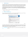
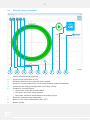
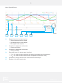
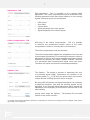
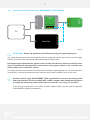
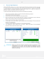
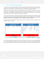
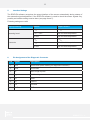
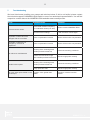
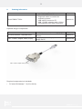
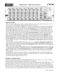
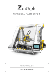
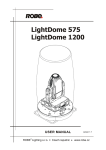
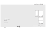
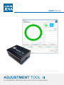
SIMPLY PRECISE
USER MANUAL
ADJUSTMENT TOOL
For NUMERIK JENA Encoders with Online Compensation
2
Index
1.
Features and Applications ���������������������������������������������������������������������������������������������������� 3
1.1
1.2
1.3
1.4
2.
EPIFLEX Software ������������������������������������������������������������������������������������������������������������������ 4
2.1
2.2
3.
Wiring Diagram ���������������������������������������������������������������������������������������������������������������������� 8
3.1
3.2
4.
Electronic Signal Adjustment ��������������������������������������������������������������������������������������������� 10
4.1
5.
Interface Settings ����������������������������������������������������������������������������������������������������������������� 12
6.
Pin Assignment of the Diagnostic Connector ������������������������������������������������������������������ 12
Functions of the ADJUSTMENT TOOL ������������������������������������������������������������������������
Dynamic Offset and Amplitude Control (Online Compensation) ����������������������������������
Scope of Delivery ���������������������������������������������������������������������������������������������������������
Suitable Encoders ��������������������������������������������������������������������������������������������������������
3
3
3
3
EPIFLEX - Installation Guide ��������������������������������������������������������������������������������������� 4
EPIFLEX - Range of Functions ������������������������������������������������������������������������������������ 5
Connecting Variants of the Diagnostic Connector ������������������������������������������������������� 8
Connection of the Encoder to the ADJUSTMENT TOOL Hardware ���������������������������� 9
Hints to the Automatic Signal Adjustment ������������������������������������������������������������������ 11
7.Troubleshooting ������������������������������������������������������������������������������������������������������������������� 13
8.
Ordering Information ����������������������������������������������������������������������������������������������������������� 14
SIMPLY PRECISE
3
1.
Features and Applications
Before delivery the encoders from NUMERIK JENA will be tested and electronically adjusted under
ideal mounting conditions. Furthermore, the sensor modules offer the possibility of an electronic signal
adjustment after the mounting into the application. This allows the user optimize the encoder signals
regarding to the mechanical mounting conditions (tolerances).
The ADJUSTMENT TOOL and the related EPIFLEX software was designed to simplify and make the
signal adjustment more effective.
1.1
•
•
•
•
•
•
Functions of the ADJUSTMENT TOOL
Representation of the sinusoidal counting signals with amplitude, offset and phase position
Representation of the position and width of the index signal
Evaluation of the mechanical mounting conditions
Automatic signal adjustment and programming of the sensor module
Electronic readjustment of the amplitude and offset of the sensor signals
Adjustment of the position and width of the index signal
1.2
Dynamic Offset and Amplitude Control (Online Compensation)
The encoders of NUMERIK JENA are equipped with a dynamic amplitude and offset control (online
compensation). The analog diode signals will be corrected to their nominal values in real time. This
reduces measuring errors caused by contamination of the scale tape as well as from inaccuracies in
the guide way. The phase position between the sine and cosine signals and the position of the index
signal are not influenced by the online compensation.
With help of the EPIFLEX Software the preadjusted nominal values of the online compensation can be
influenced (see page 7, “Online Compensation - Tab”).
1.3
•
•
•
•
•
Scope of Delivery
ADJUSTMENT TOOL black box
Diagnostic cable to connect the measuring system
USB cable to connect a PC
USB - D-SUB - adapter cable (15-pin)
Exchangeable 8-pin plug connectors
1.4
Suitable Encoders
The ADJUSTMENT TOOL is suitable for the following NUMERIK JENA - products:
LIA 20
LIA 21
LIA 22
LIK 11
LIK 21
LIK 22
LIK 23
LIK 41
Kit L2
Kit L4
LIK 2D
RIK 4
Kit R
RIA
SIMPLY PRECISE
4
2.
EPIFLEX Software
The EPIFLEX software was especially designed for the ADJUSTMENT TOOL. It offers the user versatile
possibilities to bring the encoder into service. It also allows the user to display the sensor signals and
evaluate them without using an oscilloscope or other expensive hardware. Furthermore it is possible
to program respectively optimize the encoder to the existing mounting conditions automatically.
The EPIFLEX software is available for free via download on the NUMERIK JENA website under
www.numerikjena.de. Furthermore, one can order the software with an optional USB flash drive
(see chapter 9).
The EPIFLEX software is suitable for the following operating systems:
•
Windows 7 / 8 (32 or 64 bit)
2.1
EPIFLEX - Installation Guide
Unzip the downloaded installation file or connect the optional USB flash drive to your PC. Run the
setup file and follow the instructions shown in the installation window.
Image 1
For software updates please visit our website. In our download portal you will always find the latest
version for free. We provide these software packages usually as a zipped folder. Please unzip this
folder after the download, run the setup file and follow the installation instructions. If an older software
version is installed, it is not necessary to uninstall it before.
ATTENTION! Please installl the software first, only then connect the ADJUSTMENT TOOL to
your PC!
SIMPLY PRECISE
5
2.2
EPIFLEX - Range of Functions
1
1
2
3
4
5
6
7
8
9
2
3
4
5
6
7
8
9
Image 2
Opens a file with saved parameter
Saves current parameters to a file
Reads the data from the connected sensor module
Saves the current parameters to the connected sensor module permanently
Undoes the last changed settings after connecting / saving
Window for counting signals
• Green area: shows the tolerance limits
• Red circle: shows the signal optimum
• Blue circle: shows the actual signal as a Lissajous figure
Starts the automatic signal adjustment
Button for the online compensation (ON / OFF)
Sensor number
SIMPLY PRECISE
6
Index Signal Window
10
11
12
13
14
Image 3
15
10
Signal window for the index impulse
• Green signal period: Sine signal
• Red signal period: Cosine signal
• Blue signal: Index impulse
11
Controller for adjustment of the index
• Change of position
12
Controller for adjustment of the index
• Change of width
13
Drop-down menu for signal output (interface)
• 1 VPP (for sensor modules with and also without integrated signal interpolation)
• 3 VPP (for sensor modules with external interpolation electronics / PCB)
14
Controller to change the time base of the software oscilloscope
15
Readout for the time-based value
SIMPLY PRECISE
7
Adjustment - Tab
With Adjustment - Tab it is possible to do a manual signal
adjustment. The online compensation must be deactivated. The
following parameter which have direct influence to the counting
signals (Lissajous-figure) can be adjusted:
•
•
•
•
•
LED current
Sine offset
Cosine offset
Signal amplitude of the sine signals*
Signal amplitude of the cosine signals
Image 4
Online Compensation - Tab
With help of the Online Compensation - Tab it is possible
to influence the preadjusted nominal values of the online
compensation. However, normally this is not necessary.
The online compensation must be activated.
The online compensation adjusts the amplitudes of the sine and
cosine signals dynamically. For monitoring functions the range of
adjustment of the sine and cosine amplitude parameters can be
visualized by activating the option “Update Controls”. Because
of a permanent data communication signal errors can occur.
Therefore this option should not be activated permanently.*
Image 5
Options - Tab
The Options - Tab allows to activate or deactivate the error
or monitoring signal (NAS). Furthermore the interface of the
scanning head (1 VPP or RS 422), the speed index of the sensor
module and the counting direction can be changed.*
By using a RS 422 sensor w/o signal interpolation it is necessary
to adjust the interface. Only then the counting signals can be
displayed. If the automatic signal adjustment will be started this
adjustment is not necessary. In this case the interface will be set
automatically.
Image 6
Among other things the Options - Tab displays ID and serial
number of the sensor module.*
* Encoders with external interpolation electronics or depending on the kind of the integrated sensor amplifier, these options
will possibly not be supported.
SIMPLY PRECISE
8
3.
Wiring Diagram
The encoders from NUMERIK JENA have an 8-pin diagnostic connector for signal evaluation and for
adjustment. Depending on the model, this connector is either in the scanning head (LIA 20 measuring
systems only) or in the D-Sub connector. The code on the ID label indicates the location of the connector.
ATTENTION! The power supply must be shut off when connecting or disconnecting the
diagnostic connector! Connect the diagnostic connector to the diagnostic socket
as shown in the graphics with the connecting variants. Please pay attention to
the white marking on the diagnostic connector!
For encoders with signal processing (interpolation) in the scanning head, the head’s housing cover
must be removed carefully. If the signal is processed in the connector, then the connector must be
opened.
Connecting Variants of the Diagnostic Connector
D-Sub connector
scanning head
2
diagnostic socket
connector
PCB
diagnostic socket
Connector PCB: RS 422 with interpolation
Please use diagnostic socket „2“!
Scanning head PCB: 1VPP or RS 422 without interpolation
Scanning head PCB: RS 422 with interpolation
diagnostic socket
diagnostic socket
Scanning
head PCB
(LIA 20)
Connector PCB: 1VPP or RS 422 without interpolation
Scanning
head PCB
(LIA 20)
D-Sub connector
scanning head
1
connector
PCB
3.1
Image 7
SIMPLY PRECISE
9
Connection of the Encoder to the ADJUSTMENT TOOL Hardware
or
Scanning
head PCB
(LIA 20)
diagnostic socket
diagnostic socket
D-Sub connector
adapter cable
connector
PCB
D-Sub connector
scanning head
3.2
USB
PC
USB
diagnostic socket
USB
Black Box
Image 8
ATTENTION! Please pay attention to the following during the signal adjustment:
Any noise disturbances which are interfering with the measuring system can lead to incorrect signal
settings. This will cause non-optimal signal parameters during function.
During the signal adjustment the signals of the encoder should not be used to control the drive
motor. Unintentional misadjustments could cause wrong signal values in the controller and
lead to malfunction of the drive system.
The stage should be moved without motorized drive during the signal adjustment. If a motorized drive
is necessary, a manual operation has to be used and the encoder feedback must not be used.
Encoder system, stage, ADJUSTMENT TOOL and controller must have the same ground
and earth potential. Use the included USB - D-SUB - adapter cable during the adjustment
to supply the measuring system with power over your PC, not over your controller!
If you are not in possession of the USB - D-SUB - adapter cable, you can order it separately
from NUMERIK JENA (see chapter 8).
SIMPLY PRECISE
10
4.
Electronic Signal Adjustment
With the EPIFLEX software you are able to adjust signal influencing parameters manually (see page
7). Ocassionally, that can be inconvenient, time-consuming and imprecise. Therefore, the EPIFLEX
software provides an automatic adjustment function which allows you to adjust and optimize all
parameter settings automatically very fast as well as easy.
To start the automatic adjustment please proceed as described in the following:
1.
Click on the green Start - Button to start the automatic adjustment procedure.
Subsequently a status window appears.
2.
Please follow the instructions displayed in the status window!
3.
Move the read head to the scale back and forth. In doing so it is important to cross a reference
mark to ensure that the system can also adjust this parameter correctly.
Please cross the reference mark in both directions!
4.
At the bottom of the main window a green progress bar will be displayed. This bar shows the
progress of the adjustment.
The status window displays the progress of each adjusted parameter.
5.
If the adjustment is done, please click on the Save - Button. By doing so the new adjusted
parameter will be saved to the sensor module.
Image 9
ATTENTION! Before you start the electronic adjustment please pay attention to any
contamination on the scale. This can affect the adjustment process
negatively. Clean the surface of the scale with a soft microfibre cloth and
acetone if necessary.
SIMPLY PRECISE
11
4.1
Hints to the Automatic Signal Adjustment
The movement of the measuring system during the automatic signal adjustment should be as steady
as possible. In the window for the index impulse 2 to 6 signal periods should be displayed. Otherwise
adjust the movement speed or regulate the time base of the software oscilloscope, please.
If the status window displays the message “Missing signals or too less/many periods to calculate the
parameters”, it is an indication that the movement of the measuring system is too slow or too fast.
In this case please adjust the movement speed in an appropriate way. Furthermore, you should pay
attention that you cross the reference mark during the movement.
If you get error messages in the status window after the adjustment it may have several reasons. In this
case please start the automatic adjustment procedure again to verify a legitimate failure. Additionally,
please pay attention to our mounting instructions in the data sheet of the measuring system. Often,
problems occur because of a transgression of the mechanical mounting tolerances.
In chapter 8 we have compiled some potential error causes. If these error causes do not apply to your
application, please contact us.
Image 10
If the automatic adjustment procedure is finished successfully, you can use the encoder at full capability.
If you change something regarding your mounting conditions afterwards, e.g. disassembling and
renewed assembling of the scanning head, it is recommended to do the automatic adjustment again.
SIMPLY PRECISE
12
5.
Interface Settings
The EPIFLEX software recognizes the output interface of the sensor automatically during startup of
the automatic signal adjustment. If the EPIFLEX software is used to check the sensor signals only,
possibly an interface setting must be done (see page 6 and 7).
Following settings are valid:
Signal processing
Scanning head
Connector
Interface
Output interface
1 VPP
1 VPP
1 VPP / 3 VPP
RS 422 with interpolation
RS 422
RS 422 with interpolation
1 VPP
1 VPP
3 VPP
RS 422 with interpolation
RS 422
RS 422 with interpolation
6.
Chart 1
Pin Assignment of the Diagnostic Connector
Pin
Signal
Description
1
SCL
Serial Clock (white marking on diagnostic connector)
2
SDA
Serial Data
3
RI
Index rough impulse
4
Um
Middle voltage
5
A+
Sine+
6
B+
Cosine+
7
CS
not used
8
GND
GND
Chart 2
SIMPLY PRECISE
13
7.Troubleshooting
We have listed some possible error causes and solutions below. If this is not helpful, please contact
the technical support of NUMERIK JENA GmbH or one of our authorized representations. You will find
respective contact data on the NUMERIK JENA webside www.numerikjena.de.
Error
Possible cause
Solution
Sensor data deleted. Everything
set to standard values (0 or 255)
Please contact NUMERIK JENA
Incorrect sensor settings
Load the sensor values again
Amplitude or offset cannot be
changed with the controllers
Online compensation is active
Switch off the online compensation
Amplitude or offset are not
changed by mechanical
adjustment
Online compensation is active
Switch off the online compensation
Mounting of the scanning head
outside permitted tolerances
Check the mounting conditions
Position and size of the rough
pulse outside permitted tolerances
Set the rough pulse correctly
Mounting of the scanning head
outside permitted tolerances
Check the mounting conditions
Rough pulse too wide
Set the rough pulse correctly
Incorrect sensor values
No reference mark detected
Double index impulse
No rough index pulse visible on the “Position” value greater than
oscilloscope
“Width”
“Position” must be less than
“Width”
Chart 3
SIMPLY PRECISE
14
8.
Ordering Information
Name
ADJUSTMENT TOOL
Scope of delivery / Description
• ADJUSTMENT TOOL black box
• Diagnostic cable to connect the
measuring system
• USB cable to connect a PC
• USB - D-SUB - adapter cable (15-pin)
• Exchangeable 8-pin plug connectors
Order-no.
Description
External flash drive with saved EPIFLEX
software
to supply the measuring system with
voltage via PC
Order-no.
344220-33
Optional Single Components
Name
EPIFLEX software - USB flash drive
USB - D-SUB - adapter cable (15-pin)
686802-02
341693-0M
USB - D-SUB - adapter cable (15-pin)
Required components (not included):
•
PC with OS Windows 7 / 8 (32 or 64 bit)
SIMPLY PRECISE
15
SIMPLY PRECISE
NUMERIK JENA GmbH
Im Semmicht 4
07751 Jena
Germany
Phone:
+49 3641 4728-0
Fax:
+49 3641 4728-202
E-Mail:[email protected]
www.numerikjena.de
Subject to change without prior notice.
version 10_2 2015
℗ & © NUMERIK JENA GmbH
SIMPLY PRECISE