1
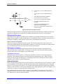
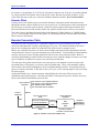
PMAC User Manual
Accuracy vs. Stability
A sensor on the load (often a linear scale) provides a more accurate measure of position than a sensor on
the motor, because its accuracy is not affected by imperfections in the motor-load coupling. However, it
can also make the axis less stable, because these coupling imperfections (typically compliance and
backlash) are now inside the loop. A sensor on the motor, while less accurate provides better stability
because these imperfections are not inside the loop.
In many cases, it is possible to get both accuracy and stability by using sensors on both the motor and the
load. In a PMAC system, simply use the load encoder to close the position loop (for accuracy), using
Ix03 to point to this encoder; and use the motor encoder to close the velocity loop (for stability), using
Ix04 to point to this encoder.
Note
When using dual feedback, the motor flags specified by Ix25 (see below) should
have the same number as the position-loop encoder. Otherwise, the hardware
position-capture function for homing will not work, and the less accurate software
position-capture function must be used. For example, if the velocity-loop encoder
is ENC1 (Ix04=$0720) and the position-loop encoder is ENC2 (Ix03=$0721), the
motor flags must be Flags 2 (Ix25=$C004) in order to use the hardware position
capture. If the flags are of a different number, the software position capture
function must be specified for homing by setting bit 16 of Ix03 to 1 (e.g.,
Ix03=$10721).
Selecting the Master Position Source
Variable Ix05 determines from which register Motor x gets its master position information. The value of
Ix05 is the address of the register. This is almost always a register in the Encoder Conversion Table that
contains processed information from a position sensor. With the default setup of the Encoder Conversion
Table, the default value of Ix05 is the register address of processed data from Encoder 2 (i.e., all motors
use Encoder 2 as a master). This setting permits a single master encoder to be brought in on the controlpanel port (J2), and have any motor follow it if that motor's following function is enabled.
The master position is the source of data for the PMAC position following function (often called
electronic gearing). This topic is covered in detail in the Synchronizing PMAC to External Events section
of this manual.
Selecting the Flag Register
Variable Ix25 determines which register Motor x uses for its flag inputs (limits, home flag, amplifier
fault, and index channel) and output (amplifier-enable/direction). The value of Ix25 is the address of the
register. Usually, this is a control/status register in the DSPGATE IC. The default value of Ix25 is the
register address of the control/status register for Encoder x (e.g. Motor 4 uses +LIM4, -LIM4, HMFL4,
FAULT4, CHC4, and AENA4/DIR4). In order to use the accurate hardware position capture function for
homing, the number of the flag set must match the number of the position-loop encoder specified by Ix03.
Selecting the Power-Up Mode
Variable Ix80 determines whether the motor will be enabled or disabled at the end of the power-up/reset
cycle. If Ix80 is 1, the motor will be enabled automatically at the end of the power-up/reset cycle, in a
closed-loop, zero velocity state, with the commanded position set equal to the actual position at the time.
If a phasing search is required for a PMAC-commutated motor, it will be done automatically. If Ix80 is 0,
the motor will be left disabled (killed); a command will be required to enable the motor: for a PMACcommutated motor, the $ command must be used; for a motor not commutated by PMAC, either the $ or
J/ command may be used, or the A command for all the motors in a coordinate system, or the <CTRLA> command for all PMAC motors.
7-4
Setting Up a Motor