1
^1 USER MANUAL
^2 PMAC Guide
^3 Universal PMAC Lite
^4 3Ax-602402-uGxx
^5 August 14, 2003
Single Source Machine Control
Power // Flexibility // Ease of Use
21314 Lassen Street Chatsworth, CA 91311 // Tel. (818) 998-2095 Fax. (818) 998-7807 // www.deltatau.com
i
© Delta Tau Data Systems, Inc - MMII
Contents
1.0 - INTRODUCTION_____________________________________________________ 1
About this manual ________________________________________________________________________________ 1
What is PMAC? _________________________________________________________________________________ 1
Configuring and programming PMAC_______________________________________________________________ 2
Hardware Setup_________________________________________________________________________________ 2
Software Setup _________________________________________________________________________________ 2
Programming PMAC ____________________________________________________________________________ 3
Universal PMAC Lite connectors and indicators _______________________________________________________ 3
J1 - Display Port Outputs (JDISP Port) _______________________________________________________________ 3
J2 - Control-Panel Port I/O (JPAN Port) ______________________________________________________________ 3
J3 - Thumbwheel Multiplexer Port I/O (JTHW Port) ____________________________________________________ 3
J4 – RS-232 Serial Port Connection (JRS232 Port)______________________________________________________ 3
J4A – RS-422 Serial Port Connection (JRS422 Port) ____________________________________________________ 3
J5 - General-Purpose Digital Inputs and Outputs (JOPTO Port) ____________________________________________ 4
J6 - Auxiliary I/O Port Connector (JXIO Port) _________________________________________________________ 4
J7 - A/D Port Connector (JS1 Port) __________________________________________________________________ 4
J8 - Position-Compare Connector (JEQU Port)_________________________________________________________ 4
J11 - Machine Connector (JMACH Connector) ________________________________________________________ 4
TB1 – Power Supply terminal block _________________________________________________________________ 4
LED Indicators _________________________________________________________________________________ 4
Fuse__________________________________________________________________________________________ 4
Universal PMAC Lite dimensions ___________________________________________________________________ 5
Universal PMAC Lite Jumpers and Connectors Layout _________________________________________________ 1
Default jumper configuration_______________________________________________________________________ 7
If something goes wrong …. ________________________________________________________________________ 8
Getting PMAC to communicate again________________________________________________________________ 8
Resetting PMAC to factory defaults _________________________________________________________________ 8
Before you call us for help_________________________________________________________________________ 8
2.0 – PMAC JUMPER CONFIGURATION _____________________________________ 9
Power-Supply Configuration Jumpers _______________________________________________________________ 9
E85, E87, E88: Analog Circuit Isolation Control _______________________________________________________ 9
E89-E90: Input Flag Supply Control________________________________________________________________ 10
Clock configuration jumpers ______________________________________________________________________ 10
E98: DAC/ADC Clock Frequency Control ___________________________________________________________ 10
E29-E33: Phase Clock Frequency Control ___________________________________________________________ 10
E48: Option CPU Clock Frequency Control __________________________________________________________ 10
E3-E6: Servo Clock Frequency Control _____________________________________________________________ 10
E34A-E38: Encoder Sample Clock _________________________________________________________________ 11
E40-E43: Servo and Phase Clock Direction Control ____________________________________________________ 11
Encoder Configuration Jumpers ___________________________________________________________________ 11
E24-E27: Encoder Complementary Line Control ______________________________________________________ 11
E22-E23: Control-Panel Handwheel Enable __________________________________________________________ 11
E72-E73: Control Panel Analog Input Enable_________________________________________________________ 11
E74-E75: Encoder Sample Clock Output ____________________________________________________________ 12
Board Reset/Save Jumpers ________________________________________________________________________ 12
E39: Reset-From-Bus Enable _____________________________________________________________________ 12
E50: Flash-Save Enable/Disable Control_____________________________________________________________ 12
E51: Re-Initialization on Reset Control______________________________________________________________ 12
E93-E94: Reset from Bus by Software Enable ________________________________________________________ 12
E103: Watchdog Timer disable ____________________________________________________________________ 13
E106: Power-Up/Reset Load Source________________________________________________________________ 13
Communication Jumpers _________________________________________________________________________ 13
E9-E10, E13-E14: Serial Interface Configuration Control________________________________________________ 13
E44-E47: Serial Baud Rate Selection _______________________________________________________________ 13
E49: Serial Communications Parity Control __________________________________________________________ 14
E66-E71, E91-E92: ISA Bus Base Address Control ____________________________________________________ 14
E54-E55, E57-E59, E61-63, E65: Interrupt Source Control ______________________________________________ 16
E76-E84, E86: Host Interrupt Signal Select___________________________________________________________ 16
E107-E108: Serial Port Configure__________________________________________________________________ 16
I/O configuration jumpers ________________________________________________________________________ 16
E1-E2: Machine Output Supply Configure ___________________________________________________________ 16
E7: Machine Input Source/Sink Control _____________________________________________________________ 17
E17A - E17D: Amplifier-Enable Polarity Control______________________________________________________ 17
E28: Following Error/Watchdog Timer Signal Control__________________________________________________ 17
E100: Auxiliary Signals Supply Control _____________________________________________________________ 17
E101-E102: Auxiliary Signals Output voltage configure ________________________________________________ 18
E109: Display Port Configuration __________________________________________________________________ 18
E110: Expansion Port Configuration________________________________________________________________ 18
Reserved configuration jumpers ___________________________________________________________________ 18
E0: Reserved for future use _______________________________________________________________________ 18
3.0 – WIRING GUIDELINES _______________________________________________ 19
Ground loops ___________________________________________________________________________________ 19
Star ground connection __________________________________________________________________________ 19
Opto-isolation circuits ____________________________________________________________________________ 20
EMI, Electromagnetic Interference _________________________________________________________________ 20
Twisted wires _________________________________________________________________________________ 20
Shielded cable _________________________________________________________________________________ 21
Wires separation and length_______________________________________________________________________ 21
Flat cable shielding ______________________________________________________________________________ 21
Basic rules for proper wiring ______________________________________________________________________ 22
4.0 – MACHINE CONNECTIONS ___________________________________________ 23
Power Supplies__________________________________________________________________________________ 23
Digital Power Supply ___________________________________________________________________________ 23
Analog Power Supply ___________________________________________________________________________ 23
Flags Power Supply (optional) ____________________________________________________________________ 24
Overtravel limits and Home switches _______________________________________________________________ 24
Types of overtravel limits ________________________________________________________________________ 24
Home switches ________________________________________________________________________________ 24
Motor signals connections_________________________________________________________________________ 25
Incremental Encoder Connection __________________________________________________________________ 25
DAC Output signals ____________________________________________________________________________ 25
Amplifier enable signal (AENAx/DIRn)_____________________________________________________________ 26
Amplifier fault signal (FAULTn) __________________________________________________________________ 27
General-Purpose Digital Inputs and Outputs (JOPTO Port) ____________________________________________ 28
J5 (JOPTO): I/O Port Connector ___________________________________________________________________ 29
Serial Connections_______________________________________________________________________________ 30
J4 (JRS232) SERIAL PORT CONNECTOR _________________________________________________________ 31
J4A (JRS422): Serial Port Connector _______________________________________________________________ 32
Machine Connections Example ____________________________________________________________________ 33
ACC-8P/ACC-8D Breakout Board _________________________________________________________________ 34
J8 (JEQU): POSITION-COMPARE CONNECTOR __________________________________________________ 36
TB1 (JPWR): POWER SUPPLY __________________________________________________________________ 36
5.0 – PROGRAMMING PMAC _____________________________________________ 37
Moving a motor: Jog commands and Motion Programs ________________________________________________ 37
Axes and Coordinate Systems _____________________________________________________________________ 38
Online Commands_______________________________________________________________________________ 38
Buffered (Program) Commands ___________________________________________________________________ 39
COMPUTATIONAL FEATURES _________________________________________________________________ 39
I-variables ____________________________________________________________________________________ 39
P-Variables ___________________________________________________________________________________ 40
Q-Variables ___________________________________________________________________________________ 40
M-Variables __________________________________________________________________________________ 41
Array capabilities_______________________________________________________________________________ 42
Operators_____________________________________________________________________________________ 42
Functions_____________________________________________________________________________________ 43
Comparators __________________________________________________________________________________ 44
I-variables setup_________________________________________________________________________________ 44
Motor definition I-variables_______________________________________________________________________ 44
Motor safety I-variables__________________________________________________________________________ 44
‘S’ curve and linear acceleration variables____________________________________________________________ 45
Rate vs Time: programming the maximum acceleration parameters ________________________________________ 46
Benefits of using ‘S’ curve acceleration profiles _______________________________________________________ 46
Motor movement I-variables ______________________________________________________________________ 46
Servo Control I-Variables ________________________________________________________________________ 47
Coordinate System I-variables_____________________________________________________________________ 47
Encoder/Flag Setup I-variables ____________________________________________________________________ 48
Encoder Conversion Table ________________________________________________________________________ 48
Jogging Moves __________________________________________________________________________________ 48
Jog Acceleration _______________________________________________________________________________ 48
Jog Speed ____________________________________________________________________________________ 49
Jog Commands ________________________________________________________________________________ 49
Indefinite Jog Commands ________________________________________________________________________ 49
Jogging To A Specified Position ___________________________________________________________________ 49
Jog Moves Specified By A Variable ________________________________________________________________ 49
Jog-Until-Trigger_______________________________________________________________________________ 50
Homing Search Moves ___________________________________________________________________________ 50
Homing Acceleration ___________________________________________________________________________ 50
Homing Speed_________________________________________________________________________________ 51
Home Trigger Condition _________________________________________________________________________ 51
Specify Flag Set _______________________________________________________________________________ 51
Software Capture Option_________________________________________________________________________ 51
Trigger Signal(s) & Edge(s) ______________________________________________________________________ 52
Torque-Mode Triggering_________________________________________________________________________ 52
Merits of Dual Trigger___________________________________________________________________________ 52
Action on Trigger ______________________________________________________________________________ 53
Home Command _______________________________________________________________________________ 53
On-Line Command _____________________________________________________________________________ 53
Monitoring for Finish ___________________________________________________________________________ 53
Monitoring for Errors ___________________________________________________________________________ 53
Buffered Program Command _____________________________________________________________________ 53
Homing from a PLC Program _____________________________________________________________________ 54
Motion vs. PLC Program Homing__________________________________________________________________ 54
Zero-Move Homing ____________________________________________________________________________ 54
Homing Into a Limit Switch ______________________________________________________________________ 55
Multi-Step Homing Procedures____________________________________________________________________ 56
Which Direction to Home? _______________________________________________________________________ 56
Already Into Home? ____________________________________________________________________________ 57
Command and Send statements____________________________________________________________________ 58
PMAC position registers__________________________________________________________________________ 59
6.0 - MOTION PROGRAMS _______________________________________________ 61
Coordinate Systems______________________________________________________________________________ 61
Axis definitions ________________________________________________________________________________ 61
Axis Definition Statements _______________________________________________________________________ 62
Writing a MOTION PROGRAM __________________________________________________________________ 62
Running a MOTION PROGRAM _________________________________________________________________ 63
Subroutines and Subprograms_____________________________________________________________________ 64
Passing Arguments to Subroutines _________________________________________________________________ 65
How PMAC Executes a Motion Program ____________________________________________________________ 65
Linear blended moves ____________________________________________________________________________ 66
Notes about linear interpolation moves ______________________________________________________________ 68
Circular Interpolation____________________________________________________________________________ 70
Splined Moves __________________________________________________________________________________ 72
PVT-Mode Moves _______________________________________________________________________________ 73
Other programming features ______________________________________________________________________ 75
Internal Timebase, the feedrate override _____________________________________________________________ 75
Synchronous M-Variable Assignment_______________________________________________________________ 75
Axis Transformation Matrices_____________________________________________________________________ 75
Learning a Motion Program ______________________________________________________________________ 75
7.0 - PLC PROGRAMS ___________________________________________________ 77
Entering a PLC Program _________________________________________________________________________ 78
PLC Program Structure __________________________________________________________________________ 78
Calculation Statements ___________________________________________________________________________ 78
Conditional Statements ___________________________________________________________________________ 79
Level-Triggered Conditions: ______________________________________________________________________ 79
Edge-Triggered Conditions: ______________________________________________________________________ 79
WHILE Loops __________________________________________________________________________________ 79
COMMAND and SEND statements ________________________________________________________________ 80
Timers ________________________________________________________________________________________ 80
8.0 - TROUBLESHOOTING SECTION_______________________________________ 83
Resetting PMAC to factory defaults ________________________________________________________________ 83
The watchdog timer (red LED) ____________________________________________________________________ 83
Establishing communications ______________________________________________________________________ 84
General ______________________________________________________________________________________ 84
Bus Communications ___________________________________________________________________________ 84
Serial communications __________________________________________________________________________ 85
Motor parameters _______________________________________________________________________________ 85
Motion programs________________________________________________________________________________ 86
PLC programs __________________________________________________________________________________ 87
9.0 – I-VARIABLES______________________________________________________ 89
GLOBAL I-VARIABLES ________________________________________________________________________ 89
I1 Serial Port Mode _____________________________________________________________________________ 89
I5 PLC Programs On/Off ______________________________________________________________________ 90
I6 Error Reporting Mode_______________________________________________________________________ 90
I7 In-Position Number of Cycles_________________________________________________________________ 91
I8 Real Time Interrupt Period ___________________________________________________________________ 92
I9 Full/Abbreviated Program Listing Form _________________________________________________________ 92
I13
Programmed Move Segmentation Time _______________________________________________________ 93
I15
Degree/Radian Control for User Trig Functions _________________________________________________ 94
I50
Rapid Move Mode Control_________________________________________________________________ 94
I52
'\' Program Hold Slew Rate _________________________________________________________________ 94
I53
Program Step Mode Control ________________________________________________________________ 95
Motor Definition I-Variables ______________________________________________________________________ 95
Ix00 Motor x Activate_________________________________________________________________________ 95
Ix01 Motor x PMAC-Commutation Enable ________________________________________________________ 95
Ix02 Motor x Command Output (DAC) Address ____________________________________________________ 96
Ix03 Motor x Position Loop Feedback Address _____________________________________________________ 97
Ix04 Motor x Velocity Loop Feedback Address _____________________________________________________ 98
Ix05 Motor x Master (Handwheel) Position Address _________________________________________________ 98
Ix06 Motor x Master (Handwheel) Following Enable_________________________________________________ 99
Ix07 Motor x Master (Handwheel) Scale Factor _____________________________________________________ 99
Ix08 Motor x Position Scale Factor_______________________________________________________________ 99
Ix09 Motor x Velocity Loop Scale Factor_________________________________________________________ 100
Motor Safety I-Variables ________________________________________________________________________ 100
Ix11 Motor x Fatal (Shutdown) Following Error Limit_______________________________________________ 100
Ix12 Motor x Warning Following Error Limit _____________________________________________________ 101
Ix13 Motor x Positive Software Position Limit_____________________________________________________ 101
Ix14 Motor x Negative Software Position Limit ____________________________________________________ 102
Ix15 Motor x Deceleration Rate on Position Limit or Abort ___________________________________________ 102
Ix16 Motor x Maximum Permitted Motor Program Velocity __________________________________________ 103
Ix17 Motor x Maximum Permitted Motor Program Acceleration_______________________________________ 103
Ix19 Motor x Maximum Permitted Motor Jog/Home Acceleration _____________________________________ 104
Motor Movement I-Variables_____________________________________________________________________ 105
Ix20 Motor x Jog/Home Acceleration Time _______________________________________________________ 105
Ix21 Motor x Jog/Home S-Curve Time __________________________________________________________ 105
Ix22 Motor x Jog Speed ______________________________________________________________________ 105
Ix23 Motor x Homing Speed and Direction _______________________________________________________ 106
Ix25 Motor x Limit/Home Flag/Amp Flag Address _________________________________________________ 106
Ix26 Motor x Home Offset ____________________________________________________________________ 109
Ix27 Motor x Position Rollover Range ___________________________________________________________ 109
Ix28 Motor x In-position Band _________________________________________________________________ 110
Ix29 Motor x Output - or First Phase - DAC Bias___________________________________________________ 110
Servo Control I-Variables________________________________________________________________________ 111
Ix30 Motor x PID Proportional Gain_____________________________________________________________ 111
Ix31 Motor x PID Derivative Gain ______________________________________________________________ 112
Ix32 Motor x PID Velocity Feedforward Gain _____________________________________________________ 112
Ix33 Motor x PID Integral Gain ________________________________________________________________ 112
Ix34 Motor x PID Integration Mode _____________________________________________________________ 113
Ix35 Motor x PID Acceleration Feedforward Gain __________________________________________________ 113
Ix68 Motor x Friction Feedforward______________________________________________________________ 114
Ix69 Motor x Output Command (DAC) Limit _____________________________________________________ 114
Ix80 Motor x Power-Up Mode _________________________________________________________________ 115
COORDINATE SYSTEM I-VARIABLES _________________________________________________________ 115
Ix87 Coordinate System x Default Program Acceleration Time ________________________________________ 115
Ix88 Coordinate System x Default Program S-Curve Time ___________________________________________ 116
Ix89 Coordinate System x Default Program Feedrate/Move Time ______________________________________ 117
Ix90 Coordinate System x Feedrate Time Units ____________________________________________________ 117
Ix91 Coordinate System x Default Working Program Number_________________________________________ 118
Ix92 Coordinate System x Move Blend Disable ____________________________________________________ 118
Ix94 Coordinate System x Time Base Slew Rate (and Limit) __________________________________________ 118
Ix95 Coordinate System x Feed Hold Deceleration Rate _____________________________________________ 119
Ix96 Coordinate System x Circle Error Limit ______________________________________________________ 119
ENCODER/FLAG SETUP I-VARIABLES _________________________________________________________ 120
I900, I905, ... I975 Encoder n Decode Control "Encoder I-Variable 0" ____________________________________ 120
I902, I907, ... I977 Encoder n Position Capture Control "Encoder I-Variable 2" _____________________________ 121
I903, I908, ... I978 Encoder n Flag Select Control "Encoder I-Variable 3"__________________________________ 122
10.0 – ONLINE COMMANDS _____________________________________________ 123
<CONTROL-A> _______________________________________________________________________________ 123
<CONTROL-B> _______________________________________________________________________________ 123
<CONTROL-C> _______________________________________________________________________________ 124
<CONTROL-D> _______________________________________________________________________________ 124
<CONTROL-F> _______________________________________________________________________________ 125
<CONTROL-G> _______________________________________________________________________________ 125
<CONTROL-H> _______________________________________________________________________________ 125
<CONTROL-I>________________________________________________________________________________ 126
<CONTROL-K> _______________________________________________________________________________ 126
<CONTROL-M>_______________________________________________________________________________ 126
<CONTROL-O> _______________________________________________________________________________ 127
<CONTROL-P> _______________________________________________________________________________ 127
<CONTROL-Q> _______________________________________________________________________________ 128
<CONTROL-R> _______________________________________________________________________________ 128
<CONTROL-S> _______________________________________________________________________________ 129
<CONTROL-V> _______________________________________________________________________________ 129
<CONTROL-X> _______________________________________________________________________________ 129
<CONTROL-Y> _______________________________________________________________________________ 130
<CONTROL-Z> _______________________________________________________________________________ 130
#_____________________________________________________________________________________________ 131
#{constant} ____________________________________________________________________________________ 131
#{constant}-> __________________________________________________________________________________ 132
#{constant}->0 _________________________________________________________________________________ 132
#{constant}->{axis definition}_____________________________________________________________________ 133
$_____________________________________________________________________________________________ 134
$$$___________________________________________________________________________________________ 135
$$$***________________________________________________________________________________________ 136
% ___________________________________________________________________________________________ 136
%{constant} ___________________________________________________________________________________ 137
&{constant} ___________________________________________________________________________________ 137
& ____________________________________________________________________________________________ 138
/ _____________________________________________________________________________________________ 138
?_____________________________________________________________________________________________ 139
??____________________________________________________________________________________________ 143
???___________________________________________________________________________________________ 147
\ _____________________________________________________________________________________________ 149
A ____________________________________________________________________________________________ 150
ABS__________________________________________________________________________________________ 151
{axis}={constant} _______________________________________________________________________________ 151
B{constant}____________________________________________________________________________________ 152
CLEAR ______________________________________________________________________________________ 153
CLOSE_______________________________________________________________________________________ 153
{constant} _____________________________________________________________________________________ 154
DATE ________________________________________________________________________________________ 154
DEFINE TBUF ________________________________________________________________________________ 155
DELETE GATHER ____________________________________________________________________________ 155
DELETE TBUF________________________________________________________________________________ 156
DISABLE PLC ________________________________________________________________________________ 156
ENABLE PLC _________________________________________________________________________________ 157
F ____________________________________________________________________________________________ 157
FRAX ________________________________________________________________________________________ 158
H ____________________________________________________________________________________________ 159
HOME _______________________________________________________________________________________ 159
HOMEZ______________________________________________________________________________________ 160
I{constant} ____________________________________________________________________________________ 160
I{constant}={expression}_________________________________________________________________________ 161
I{constant}=* __________________________________________________________________________________ 162
INC __________________________________________________________________________________________ 162
J_____________________________________________________________________________________________ 163
J+ ___________________________________________________________________________________________ 163
J- ____________________________________________________________________________________________ 163
J/ ____________________________________________________________________________________________ 164
J:{constant} ___________________________________________________________________________________ 164
J:* ___________________________________________________________________________________________ 165
J= ___________________________________________________________________________________________ 165
J={constant}___________________________________________________________________________________ 166
J=* __________________________________________________________________________________________ 166
J=={constant}__________________________________________________________________________________ 167
J^{constant}___________________________________________________________________________________ 168
J^* __________________________________________________________________________________________ 168
{jog command}^{constant}_______________________________________________________________________ 169
K ____________________________________________________________________________________________ 170
LEARN ______________________________________________________________________________________ 170
LIST _________________________________________________________________________________________ 171
LIST PC ______________________________________________________________________________________ 172
LIST PE ______________________________________________________________________________________ 172
LIST PLC ____________________________________________________________________________________ 173
LIST PROGRAM ______________________________________________________________________________ 173
M{constant} ___________________________________________________________________________________ 175
M{constant}={expression} _______________________________________________________________________ 175
M{constant}-> _________________________________________________________________________________ 176
M{constant}->* ________________________________________________________________________________ 176
M{constant}->D:{address} _______________________________________________________________________ 177
M{constant}->L:{address} _______________________________________________________________________ 177
M{constant}->X/Y:{address} _____________________________________________________________________ 178
MFLUSH _____________________________________________________________________________________ 179
O{constant} ___________________________________________________________________________________ 179
OPEN PLC ___________________________________________________________________________________ 180
OPEN PROGRAM _____________________________________________________________________________ 181
P ____________________________________________________________________________________________ 182
P{constant}____________________________________________________________________________________ 182
P{constant}={expression} ________________________________________________________________________ 183
PASSWORD={string}___________________________________________________________________________ 183
PC ___________________________________________________________________________________________ 184
PE ___________________________________________________________________________________________ 185
PMATCH_____________________________________________________________________________________ 185
Q ____________________________________________________________________________________________ 186
Q{constant} ___________________________________________________________________________________ 187
Q{constant}={expression} ________________________________________________________________________ 187
R ____________________________________________________________________________________________ 188
R[H]{address} _________________________________________________________________________________ 188
S ____________________________________________________________________________________________ 189
SAVE ________________________________________________________________________________________ 190
SIZE _________________________________________________________________________________________ 191
TYPE ________________________________________________________________________________________ 191
UNDEFINE ___________________________________________________________________________________ 192
UNDEFINE ALL ______________________________________________________________________________ 193
V ____________________________________________________________________________________________ 193
VERSION ____________________________________________________________________________________ 194
W{address} ___________________________________________________________________________________ 194
Z ____________________________________________________________________________________________ 195
11 – BUFFER COMMANDS ______________________________________________ 197
{axis}{data}[{axis}{data}...]_______________________________________________________________________ 197
{axis}{data}:{data} [{axis}{data}:{data}...] __________________________________________________________ 197
{axis}{data}^{data}[{axis}{data}^{data}...] __________________________________________________________ 198
{axis}{data} [{axis}{data}...] {vector}{data} [{vector}{data}...]___________________________________________ 199
A{data}_______________________________________________________________________________________ 200
ABS__________________________________________________________________________________________ 201
ADDRESS ____________________________________________________________________________________ 201
ADIS{constant} ________________________________________________________________________________ 202
AND ({condition}) ______________________________________________________________________________ 203
AROT{constant} _______________________________________________________________________________ 203
B{data} _______________________________________________________________________________________ 204
BLOCKSTART________________________________________________________________________________ 204
BLOCKSTOP _________________________________________________________________________________ 205
C{data}_______________________________________________________________________________________ 205
CALL ________________________________________________________________________________________ 206
CIRCLE1_____________________________________________________________________________________ 207
CIRCLE2_____________________________________________________________________________________ 207
COMMAND"{command}" ______________________________________________________________________ 208
COMMAND^{letter} ___________________________________________________________________________ 209
DELAY{data} _________________________________________________________________________________ 210
DISABLE PLC {constant}[,{constant}...] ___________________________________________________________ 211
DISPLAY [{constant}] "{message}" _______________________________________________________________ 211
DISPLAY ... {variable} __________________________________________________________________________ 212
DWELL ______________________________________________________________________________________ 212
ELSE ________________________________________________________________________________________ 213
ENABLE PLC _________________________________________________________________________________ 214
ENDIF _______________________________________________________________________________________ 215
ENDWHILE __________________________________________________________________________________ 215
F{data} _______________________________________________________________________________________ 216
FRAX ________________________________________________________________________________________ 217
GOSUB ______________________________________________________________________________________ 218
GOTO _______________________________________________________________________________________ 218
HOME _______________________________________________________________________________________ 219
HOMEZ______________________________________________________________________________________ 220
I{data} _______________________________________________________________________________________ 221
I{constant}={expression}_________________________________________________________________________ 221
IDIS{constant} _________________________________________________________________________________ 222
IF ({condition}) ________________________________________________________________________________ 222
INC __________________________________________________________________________________________ 223
IROT{constant}________________________________________________________________________________ 224
J{data} _______________________________________________________________________________________ 225
K{data}_______________________________________________________________________________________ 225
LINEAR______________________________________________________________________________________ 226
M{constant}={expression} _______________________________________________________________________ 226
M{constant}=={expression} ______________________________________________________________________ 227
M{constant}&={expression}______________________________________________________________________ 227
M{constant}|={expression} _______________________________________________________________________ 228
M{constant}^={expression} ______________________________________________________________________ 228
N{constant} ___________________________________________________________________________________ 229
NORMAL ____________________________________________________________________________________ 229
O{constant} ___________________________________________________________________________________ 230
OR({condition}) ________________________________________________________________________________ 231
P{constant}={expression} ________________________________________________________________________ 231
PSET_________________________________________________________________________________________ 232
PVT{data} ____________________________________________________________________________________ 232
Q{constant}={expression} ________________________________________________________________________ 233
R{data}_______________________________________________________________________________________ 234
RAPID _______________________________________________________________________________________ 234
READ ________________________________________________________________________________________ 235
RETURN _____________________________________________________________________________________ 236
SEND ________________________________________________________________________________________ 237
SEND^{letter} _________________________________________________________________________________ 238
SPLINE1 _____________________________________________________________________________________ 239
SPLINE2 _____________________________________________________________________________________ 240
STOP ________________________________________________________________________________________ 241
TA{data} _____________________________________________________________________________________ 241
TINIT ________________________________________________________________________________________ 242
TM{data} _____________________________________________________________________________________ 242
TS{data} ______________________________________________________________________________________ 243
TSELECT{constant}____________________________________________________________________________ 244
U{data}_______________________________________________________________________________________ 244
V{data}_______________________________________________________________________________________ 245
W{data} ______________________________________________________________________________________ 245
WAIT ________________________________________________________________________________________ 245
WHILE({condition}) ____________________________________________________________________________ 246
X{data}_______________________________________________________________________________________ 247
Y{data}_______________________________________________________________________________________ 248
Z{data} _______________________________________________________________________________________ 248
APPENDIX SECTION ___________________________________________________ 249
1.0 - Introduction
About this manual
This manual is the main source of information for installing and programming the Universal PMAC-Lite motion controller
for a typical application. A typical application in this case is composed of up to four amplifiers each requiring a single ±10
Volts differential command signal or DAC, a single quadrature incremental encoder per motor and a maximum of 8
general-purpose digital inputs and outputs.
The different sections on this manual are ordered in the following sequence:
-
Description of PMAC capabilities and features
Description of PMAC on-board configuration jumpers
Complete description of how to connect PMAC to the machine
Complete description of how to program PMAC
Description of the EZ-PMAC Setup Software
The chapters on this manual do not have an exact continuity and can be referenced or skipped as necessary.
The PMAC motion controller is very rich in features and expansion capabilities. Because this manual illustrates the
implementation of PMAC in a typical application, some of the PMAC advanced features are not described. Further
information of all PMAC features can be obtained from the PMAC Software Reference, the PMAC User’s Manual and the
PMAC Hardware Reference.
!
It is strongly recommended to use the “EZ-PMAC” program as a software tool for configuring and
programming PMAC. All the example programs provided in this manual can be found in the
“samples” folder of the EZ-PMAC Setup Software installation directory.
What is PMAC?
PMAC, pronounced “Pe’-MAC”, stands for Programmable Multi-Axis Controller. It is a family of high-performance servo
motion controllers capable of commanding up to 32 axes of motion simultaneously with a high level of sophistication.
The Universal PMAC-Lite board, member of the PMAC family, is a 4-axis motion controller. The term “Lite” stands to
indicate a maximum of four on-board axes of motion control. The term “Universal” indicates that this motion controller can
have different types of on-board backup memory, either battery based type or flash type.
Each axis is controller by an independent channel circuitry, which in turn is composed of the following features:
•
•
•
•
A single differential 16-bits DAC output
Amplifier enable output
One quadrature incremental encoder input
Four dedicated flag inputs: two end-of-travel limits, one home input and one amplifier fault input
The Univeral PMAC-Lite can be programmed to control the motion of up to four motors in any coordinated fashion, either
independently of each other or coordinated with, for example, linear or circular interpolation.
The Univeral PMAC-Lite is not only a very sophisticated motion controller but it is also a PLC, Programmable Logic
Controller, device. PLC programs in PMAC run conveniently independently of each other and of motion programs and can
be very tightly synchronized to the motion sequence.
Page - 1
1.0 - Introduction
The Univeral PMAC-Lite can be installed inside a computer on an ISA bus type, and be programmed through bus
communications. Alternatively, it can be installed in a stand-alone configuration outside the computer and programmed
using serial communications. Either RS-232 or RS-422 serial communications are supported.
PMAC has its own on-board memory. Programs and motion parameters can be kept in memory without the need to reprogram each time PMAC is power up.
Standard Features for a typical application
•
•
•
•
•
Motorola DSP 56k Digital Signal Processor
4 digital-to-analog converter (DAC) outputs
4 full encoder channels
16 General Purpose I/O, OPTO-22 compatible
Overtravel limit, home, amplifier fault/enable
flags
Display port for LCD and VFD displays
Bus, RS-422 and/or RS-232 Control
Stand-Alone Operation
•
•
•
•
•
•
•
•
•
•
•
•
Linear and Circular Interpolation
256 motion programs capacity
Asynchronous PLC program capability
36-bit position range (+/- 64 billion counts)
16-bit DAC Output Resolution
“S-curve” Acceleration and Deceleration
Cubic Trajectory Calculations, Splines
Position, velocity and time PVT move types
Advanced PID servo motion algorithms
Configuring and programming PMAC
Hardware Setup
On the PMAC, you will see many jumpers (pairs of metal prongs), called E-points. Some have been shorted together;
others have been left open. These jumpers customize the hardware features of the board for a given application. Some of
these jumpers set, for example, the baud rate for serial communications while others determine, for example, the type of
amplifier enable signals that PMAC can output.
It is strongly recommended to check each jumper configuration before installation to the machine. Details of each jumper
function and setting are provided in following chapters of this manual. Once PMAC jumpers are properly set it is possible to
install it in the machine either in a stand-alone configuration or inside the computer on the ISA bus.
Software Setup
PMAC has a large set of Initialization parameters (I-variables) that determine the "personality" of the card for a specific
application. Many of these are used to configure a motor properly. Once set up, these variables may be stored in nonvolatile EAROM memory (using the SAVE command) so the card is always configured properly (PMAC loads the
EAROM I-variable values into RAM on power-up).
!
The EZ-PMAC Setup Software provides dedicated screens as well as a terminal window for
configuring each I-variable
In a terminal window the value of any I- variable may be queried simply by typing in the name of the I- variable. For
instance, typing I900<CR> causes the value of the I900 to be returned. The value may be changed by typing in the name,
an equals sign, and the new value (e.g. I900=3<CR>). Remember that if you change any I-variables during this setup, you
must use the SAVE command before you power down or reset the card, or you will lose the changes that you have made.
Page - 2
1.0 - Introduction
Programming PMAC
Buffered commands for Motion programs or PLC programs are entered in any text file and then downloaded to PMAC with
the EZ-PMAC Setup Software or equivalent software.
A different set of commands, the online commands, allow to immediately jog motors, change variables, report variables
values, start and stop programs, query for status information and even write short motion and PLC programs from the
terminal window.
Once loaded each enabled PLC program will run automatically on power-up provided that the I5 I-variable has been
properly set. Motion programs can be started from the terminal window by typing, for example, the B1R command or can
be automatically started on power-up from a PLC program.
"
Always remember to type “SAVE” in the terminal window to keep any changes that you might have
made in PMAC’s memory. The EZ-PMAC Setup Software always reminds to save the PMAC
parameters on each exit.
Universal PMAC Lite connectors and indicators
J1 - Display Port Outputs (JDISP Port)
The JDISP connector allows connection of the ACC-12 or ACC-12A liquid crystal displays, or of the ACC-12C vacuum
fluorescent display. Both text and variable values may be shown on these displays through the use of the DISPLAY
command, executing in either motion or PLC programs.
J2 - Control-Panel Port I/O (JPAN Port)
This connector is considered an advanced feature and it is not used on a standard application.
J3 - Thumbwheel Multiplexer Port I/O (JTHW Port)
The Thumbwheel Multiplexer Port, or Multiplexer Port, on the JTHW connector has eight input lines and eight output lines.
The output lines can be used to multiplex large numbers of inputs and outputs on the port, and Delta Tau provides accessory
boards and software structures (special M-variable definitions) to capitalize on this feature. Up to 32 of the multiplexed I/O
boards may be daisy-chained on the port, in any combination.
J4 – RS-232 Serial Port Connection (JRS232 Port)
Both RS-232 and RS-422 ports are always provided, and jumpers must be set correctly to use the port of your choice.
Jumpers E107 and E108 must connect pins 1 and 2 to use the RS-232 port on the J4 connector. J4 and J4A cannot be used
at the same time.
J4A – RS-422 Serial Port Connection (JRS422 Port)
Both RS-232 and RS-422 ports are always provided, and jumpers must be set correctly to use the port of your choice.
Jumpers E107 and E108 must connect pins 2 and 3 to use the RS-422 port on the J4A connector. J4 and J4A cannot be used
at the same time.
Page - 3
1.0 - Introduction
J5 - General-Purpose Digital Inputs and Outputs (JOPTO Port)
PMAC's JOPTO connector provides eight general-purpose digital inputs and eight general-purpose digital outputs. Each
input and each output has its own corresponding ground pin in the opposite row. The 34-pin connector was designed for
easy interface to OPTO-22 or equivalent optically isolated I/O modules. Delta Tau's Accessory 21F is a six-foot cable for
this purpose.
J6 - Auxiliary I/O Port Connector (JXIO Port)
This connector is considered an advanced feature and it is not used on a standard application.
J7 - A/D Port Connector (JS1 Port)
This connector is considered an advanced feature and it is not used on a standard application.
J8 - Position-Compare Connector (JEQU Port)
For a typical application, the most important feature of this connector is to allow the connection of an external power supply
for using flag sensors in the 12 to 24 Volts range, which is otherwise limited to up to 15 Volts operation. Other features of
this connector are considered advanced and are not used on a standard application.
J11 - Machine Connector (JMACH Connector)
This connector, labeled J11, contains the pins for four channels of machine I/O: analog outputs, incremental encoder inputs,
and associated input and output flags, plus power-supply connections. Lines on this connector are almost always accessed
through the ACC-8P or ACC-8D breakout boards.
TB1 – Power Supply terminal block
This terminal block can be used to provide the input for the power supply for the circuits on the PMAC-Lite board when it
is not in a bus configuration. However, it is recommended to use the ACC-8P or equivalent terminal block for the power
supply connections.
LED Indicators
The Universal PMAC Lite has 3 LED indicators: red, yellow, and green. When the green LED is lit, this indicates that
power is applied to the +5V input; when the red LED is lit, this indicates that the watchdog timer has tripped and shut down
the PMAC.
The yellow LED located beside the red and green LEDs, when lit, indicates that the phase-locked loop that multiplies the
CPU clock frequency from the crystal frequency on the Option CPU is operational and stable. This indicator is for
diagnostic purposes only; it may not be present on your board.
Fuse
The 5 Volts output through the J5 JOPTO connector is protected by F1, which is a 2-Amp fuse of the following type:
Manufacturer:
Part Number:
Page - 4
LittleFuse
021-273002-004
1.0 - Introduction
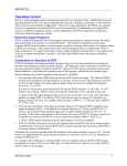
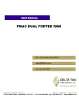
Universal PMAC Lite dimensions
Page - 5
1.0 - Introduction
D21
F1
J4
E109
J6
U44
J4A
J7
E100
J8
E101
E1
E2
E102
E0
E72
E73
E74
E75
J18
J5
E7
E17A
E17B
E17C
E17D
J9
J3
E51
E50
E49
E48
J2
E22
E23
J1
D1
D2
D3
1
E107
E108
E9
E10
E13
E14
E103
E90
E89
E34A
E34
E35
E36
E37
E38
E98
J11
E33
E32
E31
E30
E29
E110
E28
U46
E3
E4
E5
E6
E81
E82
E83
E84
E86
E87 E85 E88
TB1
E76
E77
E78
E79
E80
E91
E92
E66
E67
E68
E69
E70
E71
E54
E55
E57
E58
E59
E61
E62
E63
E65
E93
E94
E39
3
E27 E25
E40
E41
E42
E43
E44
E45
E46
E47
2
E26 E24
J20
E106
Page - 6
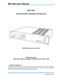
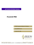
Universal PMAC Lite Jumpers and Connectors Layout
A
E0
E1
E2
E3
E4
E5
E6
E7
E9
E10
E1
E1
E1
F3
F3
F3
F3
D1
F1
F1
B
E13
E14
E17A
E17B
E17C
E17D
E22
E23
E24
E25
F1
F1
G1
G1
G1
G1
G1
G1
H2
H2
E26
E27
E28
E29
E30
E31
E32
E33
E34A
E34
C
H2
H2
E3
F3
F3
F3
E3
E3
E3
E3
E35
E36
E37
E38
E39
E40
E41
E42
E43
E44
D
E3
F3
F3
F3
D3
C2
C2
C2
C2
C2
E45
E46
E47
E48
E49
E50
E51
E54
E55
E57
E
C2
D2
D2
D1
D1
C1
C1
C3
C3
C3
E58
E59
E61
E62
E63
E65
E66
E67
E68
E69
F
C3
C3
D3
D3
D3
D3
D3
D3
D3
D3
E70
E71
E72
E73
E74
E75
E76
E77
E78
E79
D3
D3
E2
E2
E2
E2
F3
F3
F3
F3
G
E80
E81
E82
E83
E84
E85
E86
E87
E88
E89
F3
F3
F3
G3
G3
G3
G3
G3
H3
G2
H
E90
E91
E92
E93
E94
E98
E100
E101
E102
E103
G2
D3
D3
C3
C3
F3
H1
H1
H1
A1
E106
E107
E108
E109
E110
D1
D2
D3
D21
F1
A2
F1
F1
B1
C2
B1
B1
B1
G1
F1
1.0 - Introduction
Default jumper configuration
Jumper
E0
E1
E2
E3
E4
E5
E6
E7
E9
E10
E13
E14
E17A
E17B
E17C
E17D
E22
E23
E24
E25
E26
E27
E28
E29
E30
E31
E32
E33
E34A
E34
E35
E36
E37
E38
E39
E40
E41
E42
E43
E44
E45
E46
E47
E48
E49
E50
E51
E54
Location
E1
E1
E1
F3
F3
F3
F3
D1
F1
F1
F1
F1
G1
G1
G1
G1
G1
G1
H2
H2
H2
H2
E3
F3
F3
F3
E3
E3
E3
E3
E3
F3
F3
F3
D3
C2
C2
C2
C2
C2
C2
D2
D2
D1
D1
C1
C1
C3
Default
OFF
1-2
1-2
OFF
OFF
ON
ON
1-2
1-2
1-2
1-2
1-2
OFF
OFF
OFF
OFF
OFF
OFF
1-2
1-2
1-2
1-2
2-3
OFF
OFF
ON
OFF
OFF
OFF
ON
OFF
OFF
OFF
OFF
OFF
ON
ON
ON
ON
OFF
ON
ON
OFF
OFF
ON
ON
OFF
OFF
Jumper
E55
E57
E58
E59
E61
E62
E63
E65
E66
E67
E68
E69
E70
E71
E72
E73
E74
E75
E76
E77
E78
E79
E80
E81
E82
E83
E84
E85
E86
E87
E88
E89
E90
E91
E92
E93
E94
E98
E100
E101
E102
E103
E106
E107
E108
E109
E110
Location
C3
C3
C3
C3
D3
D3
D3
D3
D3
D3
D3
D3
D3
D3
E2
E2
E2
E2
F3
F3
F3
F3
F3
F3
F3
G3
G3
G3
G3
G3
H3
G2
G2
D3
D3
C3
C3
F3
H1
H1
H1
A1
A2
F1
F1
B1
C2
Default
OFF
OFF
OFF
OFF
OFF
OFF
OFF
OFF
OFF
ON
ON
ON
ON
OFF
OFF
OFF
OFF
OFF
OFF
OFF
OFF
OFF
OFF
OFF
OFF
OFF
OFF
OFF
OFF
OFF
OFF
ON
1-2
ON
ON
OFF
OFF
1-2
1-2
1-2
1-2
OFF
OFF
1-2
1-2
OFF
1-2
Page - 7
1.0 - Introduction
If something goes wrong ….
Getting PMAC to communicate again
1) Turn off PMAC or the host computer where PMAC is installed.
2) Remove all cables connected to PMAC and only connect the serial port and power cables if necessary.
3) Check that all PMAC jumpers are at the default configuration or properly changed to accommodate the particular setup
for the machine. Make sure that jumper E50 is properly installed because otherwise any “SAVE” command issued to
PMAC will not have any effect (and the problem will return when E51 is removed).
4) Install jumper E51. This is a hardware re-initialization jumper that takes effect on power-up.
5) After power-up try establishing communications again with a software package like PEWIN or EZ-PMAC Setup
Software provided by Delta Tau.
6) If communication gets established perform the reset procedure described in the following section.
Resetting PMAC to factory defaults
1) Type the following commands on the terminal window. This procedure will set all PMAC variables to their default
configuration and any Motion Program and PLC program will be erased from memory.
$$$***
P0..1023=0
Q0..1023=0
M0..1023->* M0..1023=0
UNDEFINE ALL
SAVE
;Global Reset
;Reset P-variables values
;Reset Q-variables values
;Reset M-variables definitions and values
;Undefine Coordinate Systems
;Save this initial, “clean” configuration
7) If the re-initialization E51 jumper was installed remove it at this time. Restore all PMAC connections and power it up.
8) Try communications again and configure PMAC for your application. It is strongly recommended to have a backup file
saved in the host computer with all the parameters and programs that PMAC needs to run the application. Furthermore,
since the host computer could also fail and be replaced, save the configuration file both in the host computer and in a
floppy disk stored in a safe place. This file must be downloaded and a SAVE command must be issued to PMAC.
!
The EZ-PMAC Setup Software has a set of step-by-step procedures for establishing PMAC
communications, for performing different reset procedures, and also has dedicated screens for
backup and restoring a particular PMAC configuration.
Before you call us for help
One of the most important services that Delta Tau provides is the excellent technical support for all its products. To provide
you a better service, please have the following information prepared before contacting us:
1) Your PMAC model. In this case you are working with the “Universal PMAC Lite” board. PMAC is pronounced
“Pe’-MAC” and stands for “Programmable Multi-Axis Controller”
2) The information from these commands issued from a terminal window: TYPE, VERSION and DATE.
3) The part number read from the PMAC board, which is usually located on the soldering side of the board. In this
case you will have the number 602402 followed by three more digits describing the revision number.
4) The operating system of the computer communicating with PMAC, that is, the version of Windows installed in the
host computer.
5) The name and version of the software that you are using for communicating with PMAC. In most cases this will
be either PEWIN or EZ-PMAC Setup Software, both provided by Delta Tau.
6) Prepare a concise description of the problem and identify the problem as either software or hardware related. For
example, problems with motion programs or PLC programs are software related whereas a motor that does not run
properly could be a problem either software or hardware related.
Page - 8
2.0 – PMAC Jumper Configuration
On the PMAC, you will see many jumpers (pairs of metal prongs), called E-points. Some have been shorted together;
others have been left open. These jumpers customize the hardware features of the board for a given application. Some of
these jumpers set, for example, the baud rate for serial communications while others determine, for example, the type of
amplifier enable signals that PMAC can output.
In the following description a jumper that by default is not present or removed is indicated as “OFF”. A jumper that is
present or installed is indicated as “ON”. For a three-position jumper the proper configuration will be indicated, either 1-2,
2-3 or “OFF”. For the location of each configuration jumper refer to the Universal PMAC Lite connectors and indicators
section.
Power-Supply Configuration Jumpers
(12-24V)
A+V (pin 9)
J8 JEQU
E89
E85
+12V
+5V
A+15V
E90
3
+5V
E100
1
1
3
AENAs AGND
(EQUs)
Input
Flags
DACs
AGND
AGND
V/F
E87
GND
-12V
GND
E88
P1 (Bus) / TB1
A-15V
JMACH1
E85, E87, E88: Analog Circuit Isolation Control
Default Configuration
E85
E87
E88
OFF
OFF
OFF
The PMAC-Lite board circuitry is divided in two parts that can be electrically isolated from each other. The analog circuitry
interfaces, among other signals, the amplifier control lines like the DAC (± 10 Volts) command output and amplifier enable
and fault signals. The digital circuitry includes the CPU as well as the encoder input circuitry.
These jumpers control whether the analog circuitry on the PMAC-Lite is isolated from the digital circuitry, or electrically
tied to it. In the default configuration, these jumpers are off, keeping the circuits isolated from each other (provided separate
isolated supplies are used).
Page - 9
2.0 – PMAC Jumper Configuration
Putting E87 ON ties the digital GND reference signal to the analog AGND reference signal, defeating the isolation between
the circuits. Putting E85 ON ties the digital +12V supply line to the analog A+15V supply line. Putting E88 ON ties the
digital –12V supply line to the analog A-15V supply line. Putting these jumpers on permits the bus +/-12V supply to power
PMAC’s analog circuits.
E89-E90: Input Flag Supply Control
Default Configuration
E89
E90
ON
1-2
If E90 connects pins 1 and 2 and E89 is ON, the input flags (+LIMn, -LIMn, HMFLn, and FAULTn) are supplied from the
analog A+15V supply, which can be isolated from the digital circuitry. If E90 connects pins 1 and 2 and E89 is OFF, the
input flags are supplied from a separate A+V supply brought in on pin 9 of the J8 JEQU connector. This supply can be in
the +12V to +24V range, and can be kept isolated from both the analog and digital circuits. If E90 connects pins 2 and 3,
the input flags are supplied from the digital +12V supply, and isolation from the digital circuitry is defeated.
Clock configuration jumpers
E98: DAC/ADC Clock Frequency Control
Default Configuration
E98
1-2
This jumper is related to an advanced feature and should not be changed from default.
E29-E33: Phase Clock Frequency Control
E29
OFF
Default Configuration
E30
E31
E32
ON
OFF
OFF
E33
OFF
These jumpers are related to an advanced feature and should not be changed from default.
E48: Option CPU Clock Frequency Control
Default Configuration
E48
OFF
This jumper is related to an advanced feature and should not be changed from default.
E3-E6: Servo Clock Frequency Control
E3
OFF
Default Configuration
E6
E4
E5
ON
OFF
ON
These jumpers are related to an advanced feature and should not be changed from default.
Page - 10
2.0 – PMAC Jumper Configuration
E34A-E38: Encoder Sample Clock
E34A
OFF
Default Configuration
E34
E35
E36
E37
ON
OFF
OFF
OFF
E38
OFF
These jumpers are related to an advanced feature and should not be changed from default.
E40-E43: Servo and Phase Clock Direction Control
E40
ON
Default Configuration
E43
E41
E42
ON
ON
ON
These jumpers are related to an advanced feature and should not be changed from default.
Encoder Configuration Jumpers
E24-E27: Encoder Complementary Line Control
E24
1-2
Default Configuration
E27
E25
E26
1-2
1-2
1-2
These jumpers, one per encoder, control the voltage to which the complementary channels A/, B/, and C/ are pulled. The
default setting for each jumper, connecting pins 1 and 2, ties the complementary lines to 2.5V. This setting is required for
single-ended encoders, and is best if the channel is left unconnected. If encoders with differential line drivers are used, the
setting of these jumpers does not matter. Changing the jumpers to connect pins 2 and 3 ties the complementary lines to 5V.
This setting is used for (now obsolete) complementary open-collector encoders, or if external exclusive-or loss-of-encoder
circuitry is used.
The following table shows which jumper affects which encoder channel:
ENC1
E27
ENC2
E26
ENC3
E25
ENC4
E24
E22-E23: Control-Panel Handwheel Enable
Default Configuration
E22
E23
OFF
OFF
These jumpers are related to an advanced feature and should not be changed from default.
E72-E73: Control Panel Analog Input Enable
Default Configuration
E72
E73
OFF
OFF
These jumpers are related to an advanced feature and should not be changed from default.
Page - 11
2.0 – PMAC Jumper Configuration
E74-E75: Encoder Sample Clock Output
Default Configuration
E74
E75
OFF
OFF
These jumpers are related to an advanced feature and should not be changed from default.
Board Reset/Save Jumpers
E39: Reset-From-Bus Enable
Default Configuration
E39
OFF
This jumper is related to an advanced feature and should not be changed from default.
E50: Flash-Save Enable/Disable Control
Default Configuration
E50
ON
If E50 is ON (default), the active software configuration of the PMAC can be stored to non-volatile flash memory with the
“SAVE” command. If the jumper on E50 is removed, this “SAVE” function is disabled, and the contents of the flash
memory cannot be changed.
E51: Re-Initialization on Reset Control
Default Configuration
E51
OFF
If E51 is OFF (default), PMAC executes a normal reset, loading active memory from the last saved configuration in nonvolatile flash memory. If E51 is ON, PMAC re-initializes on reset, loading active memory with the factory default values.
"
If communications with PMAC cannot be established try installing E51 and power PMAC up again.
If installing E51 enables communications type “SAVE” on the terminal window and remove the E51
jumper. All memory contents will be cleared to factory defaults.
E93-E94: Reset from Bus by Software Enable
Default Configuration
E93
E94
OFF
OFF
These jumpers are related to an advanced feature and should not be changed from default.
Page - 12
2.0 – PMAC Jumper Configuration
E103: Watchdog Timer disable
Default Configuration
E103
OFF
If E103 is installed the watchdog safety function will be disabled. This jumper is for testing purposes only.
E106: Power-Up/Reset Load Source
Default Configuration
E106
OFF
If E106 is installed when the PMAC-Lite executes its reset cycle, PMAC enters a special re-initialization mode that permits
the downloading of new firmware either through the serial port or the bus port. Under these conditions an appropriate
program like Delta Tau’s PEWIN Software allows the downloading of a firmware file.
$
Compiled PLCs must be recompiled for running under a different firmware version. Before
attempting to upgrade PMAC operational firmware make sure all of PMAC configuration has been
stored to disk on a backup file. Also, if compiled PLCs are used, make sure to store their source code
separately, which is not automatically saved in a backup file.
After the firmware has been changed, and before the memory configuration has been restored, it is
important to send the $$$*** command to clear all memory and buffers.
Communication Jumpers
E9-E10, E13-E14: Serial Interface Configuration Control
E9
ON
Default Configuration
E14
E10
E13
ON
ON
ON
The E9, E10, E13, and E14 jumpers control whether the RS-232 serial port will be in DCE or DTE format. The default
configuration permits straight-across connection to a PC DB-9 serial port.
Jump, E9-1 to E9-2 to allow ‘RXD/’ to be input on J4-3.
Jump E10-1 to E10-2 to allow ‘TXD/’ to be output on J4-5.
Jump E9-1 to E10-1 to allow ‘TXD/’ to be output on J4-3.
Jump E9-2 to E10-2 to allow ‘RXD/’ to be input on J4-5.
Jump E13-1 to E13-2 to allow ‘RTS’ to be input on J4-7.
Jump E14-1 to E14-2 to allow ‘CTS’ to be output on J4-9.
Jump E13-1 to E14-1 to allow ‘CTS’ to be output on J4-7.
Jump E13-2 to E14-2 to allow ‘RTS’ to be input on J4-9.
E44-E47: Serial Baud Rate Selection
E44
OFF
Default Configuration
E47
E45
E46
OFF
ON
ON
Page - 13
2.0 – PMAC Jumper Configuration
The configuration of these jumpers and the particular CPU option ordered (usually written on chip U13 on PMAC)
determine the baud rate at which PMAC will communicate through its J4 or J4A serial port.
BAUD RATE CONTROL
"E" POINTS
E44
E45
E46
E47
ON
ON
ON
ON
OFF
ON
ON
ON
ON
OFF
ON
ON
OFF OFF
ON
ON
ON
ON
OFF
ON
OFF
ON
OFF
ON
ON
OFF OFF
ON
OFF OFF OFF
ON
ON
ON
ON
OFF
OFF
ON
ON
OFF
ON
OFF
ON
OFF
OFF OFF
ON
OFF
ON
ON
OFF OFF
OFF
ON
OFF OFF
ON
OFF OFF OFF
OFF OFF OFF OFF
*Non-standard baud rate
BAUD RATE
20 MHz Flash CPU
(OPT 4A)
Battery CPU, 40 MHz
Flash CPU (Opt 5A)
60 MHz Flash CPU
(Opt 5B)
80 MHz Flash CPU
(Opt 5C)
DISABLED
DISABLED
DISABLED
DISABLED
300
400*
600
800*
1200
1600*
2400
3200*
4800
6400*
9600
12800*
19200
25600*
38400
600
800*
1200
1600*
2400
3200*
4800
6400*
9600
12800*
19200
25600*
38400
51200*
76800
900
1200
1800
2400
3600
4800
7200
9600
14400
19200
28800
38400
57600
76800
115200
1200
1600*
2400
3200*
4800
6400*
9600
12800*
19200
25600*
38400
51200*
76800
102400*
153600
E49: Serial Communications Parity Control
Default Configuration
E49
ON
This jumper is related to an advanced feature and should not be changed from default.
E66-E71, E91-E92: ISA Bus Base Address Control
E66
OFF
E67
ON
E68
ON
Default Configuration
E69
E70
E71
ON
ON
OFF
E91
ON
E92
ON
Jumpers E91, E92, E66, E67, E68, E69, E70, and E71 on the PMAC-Lite determine the base address of the card in the I/O
space of the host PC's expansion bus. Together, they form a binary number that specifies the 16 consecutive addresses on
the bus where the card can be found. The jumpers form the base address in the following fashion:
Jumper
Bit #
Dec Value
Hex Value
E91
11
2048
800
E92
10
1024
400
E66
9
512
200
E67
8
256
100
E68
7
128
80
E69
6
64
40
E70
5
32
20
E71
4
16
10
If a jumper is ON, the value it contributes to the base address is ZERO.
If a jumper is OFF, the value it contributes to the base address is given in the table above.
On the PMAC-Lite, the jumpers are physically arranged in the same order they are presented in the above table.
Page - 14
2.0 – PMAC Jumper Configuration
From Jumper Configuration To Address
To determine the address specified by a given jumper configuration, use the following formula:
(Decimal)
Address = 2048*E91 + 1024*E92 + 512*E66 + 256*E67 + 128*E68 + 64*E69 + 32*E70 + 16*E71
(Hexadecimal)
Address = $800*E91 + $400*E92 + $200*E66 + $100*E67 + $80*E68 + $40*E69 + $20*E70 + $10*E71
In each case, Exx = 1 if the jumper is OFF; Exx = 0 if the jumper is ON.
Example: On a PMAC card, the jumpers are in the following configuration:
E91
ON
E92
ON
E66
OFF
E67
OFF
E68
ON
E69
ON
E70
ON
E71
ON
The address can be computed as:
Decimal Address = 0 + 0 + 512 + 256 + 0 + 0 + 0 + 0 = 768
Hex Address = 0 + 0 + $200 + $100 + 0 + 0 + 0 + 0 = $300
From Address To Jumper Configuration
Once an I/O address on the PC expansion port has been selected, the following procedure can be used for setting the address
jumpers.
1.) Convert the address to a 3-digital hexadecimal value ($000 to $FFF, representing 0 to 4095). If the value does not fit in
this range, you will not be able to set PMAC for this address. Make sure the last digit is 0; only addresses divisible by 16
are permitted as PMAC base addresses.
2.) Take the first hex digit and convert it to binary. The binary digits represent bits 11 through 8 of the base address. Assign
each binary digit to jumpers as follows:
Bit #
Jumper
Digit Value
Setting for 1
Setting for 0
11(MSB)
E91
8
OFF
ON
10
E92
4
OFF
ON
9
E66
2
OFF
ON
8(LSB)
E67
1
OFF
ON
3.) Take the second hex digit and convert it to binary. The binary digits represent bits 7 through 4 of the base
address. Assign each binary digit to jumpers as follows:
Bit #
Jumper
Digit Value
Setting for 1
Setting for 0
7(MSB)
E68
8
OFF
ON
6
E69
4
OFF
ON
5
E70
2
OFF
ON
4(LSB)
E71
1
OFF
ON
Example 1: You wish to set up the card to be at base address 992 decimal on the PC expansion bus.
1.) 992 decimal is equal to 3E0 hexadecimal.
2.) The first digit of 3 is binary 0011. This sets E91 ON, E92 ON, E66 OFF, E67 OFF.
3.) The second digit of E is binary 1110. This sets E68 OFF, E69 OFF, E70 OFF, E71 ON.
Page - 15
2.0 – PMAC Jumper Configuration
Example 2: You wish to set up the card to be at base address 528 decimal on the PC expansion bus.
1.) 528 decimal is equal to 210 hexadecimal.
2.) The first digit of 2 is binary 0010. This sets E91 ON, E92 ON, E66 OFF, E67 ON.
3.) The second digit of E is binary 0001. This sets E68 ON, E69 ON, E70 ON, E71 OFF.
Example 3: You wish to set up the card to be at base address 544 decimal on the PC expansion bus.
1.) 544 decimal is equal to 220 hexadecimal.
2.) The first digit of 2 is binary 0010. This sets E91 ON, E92 ON, E66 OFF, E67 ON.
3.) The second digit of E is binary 0010. This sets E68 ON, E69 ON, E70 OFF, E71 ON.
E54-E55, E57-E59, E61-63, E65: Interrupt Source Control
E54
OFF
E55
OFF
E57
OFF
E58
OFF
Default Configuration
E59
E61
E62
OFF
OFF
OFF
E62
OFF
E63
OFF
E65
OFF
E83
OFF
E84
OFF
E86
OFF
These jumpers are related to an advanced feature and should not be changed from default.
E76-E84, E86: Host Interrupt Signal Select
E76
OFF
E77
OFF
E78
OFF
E79
OFF
Default Configuration
E80
E81
E82
OFF
OFF
OFF
These jumpers are related to an advanced feature and should not be changed from default.
E107-E108: Serial Port Configure
Default Configuration
E107
E108
1-2
1-2
Both RS-232 and RS-422 serial ports are always provided standard on the Universal PMAC-Lite board. Jumpers E107 and
E108 must be set correctly to use the port of your choice. Both jumpers E107 and E108 must connect pins 1 and 2 to use
the RS-232 port on the J4 connector. Otherwise, both jumpers E107 and E108 must connect pins 2 and 3 to use the RS-422
port on the J4A connector.
I/O configuration jumpers
E1-E2: Machine Output Supply Configure
Default Configuration
E1
E2
1-2
1-2
Chip U26 on the Universal PMAC Lite controls the general-purpose digital outputs on connector J5 JOPTO.
With the default sinking output driver IC (ULN2803A or equivalent) in U26, these jumpers must connect pins 1 and 2 to
supply the IC correctly. If this IC is replaced with a sourcing output driver IC (UDN2981A or equivalent), these jumpers
must be changed to connect pins 2 and 3 to supply the new IC correctly.
Page - 16
2.0 – PMAC Jumper Configuration
%
The jumper setting must match the type of driver IC, or damage to the IC will result.
E7: Machine Input Source/Sink Control
Default Configuration
E7
1-2
With this jumper connecting pins 1 and 2 (default) the machine input lines on the J5 JOPTO port are pulled up to +5V or the
externally provided supply voltage for the port. This configuration is suitable for sinking drivers. If the jumper is changes
to connect pins 2 and 3, these lines are pulled down to GND – this configuration is suitable for sourcing drivers.
E17A - E17D: Amplifier-Enable Polarity Control
Default Configuration
E17D
E17A
E17B
E17C
OFF
OFF
OFF
OFF
Jumpers E17A through E17D control the polarity of the amplifier enable signal for the corresponding motor 1 to 4. When
the jumper is OFF (default), the amplifier-enable line for the corresponding motor is “low true” so the enable state is lowvoltage output and sinking current, and the disable state is not conducting current. With the default ULN2803A sinking
driver used by the PMAC-Lite, this is the fail-safe option, allowing the circuit to fail in the disable state. With this jumper
ON, the amplifier-enable line is “high true” so the enable state is not conducting current, and the disable state is low-voltage
output and sinking current. This setting is not generally recommended. The following table shows which jumper affects
which channel:
AENA1
E17A
AENA2
E17B
AENA3
E17C
AENA4
E17D
E28: Following Error/Watchdog Timer Signal Control
Default Configuration
E28
2-3
Jump pin 1 to 2 to allow warning following error (Ix12) for the selected coordinate system to control "FEFCO/" on J8-57.
Jump pin 2 to 3 to cause WATCHDOG timer output to control "FEFCO/". Low TRUE output in either case.
E100: Auxiliary Signals Supply Control
Default Configuration
E100
1-2
The U54 driver IC controls the AENA and EQU signals on the J8 JEQU connector. If E100 connects pins 1 and 2, U54 will
be supplied from the analog A+15V supply, which can be isolated from the digital circuitry. If E100 connects pins 2 and 3,
U54 will be supplied from a separate A+V supply brought in on pin 9 of the J8 JEQU connector. This supply can be in the
+12V to +24V range, and can be kept isolated from the digital and analog circuits.
Page - 17
2.0 – PMAC Jumper Configuration
E101-E102: Auxiliary Signals Output voltage configure
Default Configuration
E1
E2
1-2
1-2
The U54 driver IC controls the AENA and EQU signals on the J8 JEQU connector. With the default sinking output driver
IC (ULN2803A or equivalent) in U54 for the J8 JEQU port outputs, these jumpers must connect pins 1 and 2 to supply the
IC correctly. If this IC is replaced with a sourcing output driver IC (UDN2981A or equivalent), these jumpers must be
changed to connect pins 2 and 3 to supply the new IC correctly.
%
The jumper setting must match the type of driver IC, or damage to the IC will result.
E109: Display Port Configuration
Default Configuration
E109
OFF
This jumper is related to an advanced feature and should not be changed from default.
E110: Expansion Port Configuration
Default Configuration
E110
1-2
This jumper is related to an advanced feature and should not be changed from default.
Reserved configuration jumpers
E0: Reserved for future use
Default Configuration
E0
OFF
This jumper is reserved for future use and should not be changed from default.
Page - 18
3.0 – Wiring Guidelines
Proper wiring, grounding and shielding are essential to prevent unwanted electrical noise and to assure proper servo
operation and performance. The most common symptoms resulting from improper wiring are inaccurate positioning, poor
servo control and, in the worst case, damage parts of the controller's hardware. These are some known noise sources:
1) Switches operating inductive loads such as relays, solenoids
2) Solid state relays or PWM servo amplifiers
3) Arc welding and plasma torch machines
4) Heavy current carrying wires
5) Fluorescent lights
6) Neon lights
The following notes illustrate the most common wiring problems and methods for reducing electromagnetic noise.
Ground loops
Ground is an equipotential circuit reference point. A "ground loop" can be defined as electrical grounds that are not at the
same electrical potential, namely zero volts AC and DC. As a result, a ground loop generates a potential difference along the
ground line connecting two electrical devices. This originates the following important consequences:
1) An electrical current will circulate along the ground wire dissipating power and generating heat. Wire insulators will be
degraded and eventually damaged.
2) The ground electric potential will change resulting in a wrong signal reference. Some electrical signals in PMAC will
change state above 0.7 Volts against ground. If the ground reference rises above 1 Volt an evident unreliable behavior
will result.
3) In some cases the ground line is used as a safety mechanism against electric shocks. Therefore, the ground line must be
kept as a zero volts reference point.
Star ground connection
All component chassis ground points and signal ground or common points should be tied together at a single point (star
connection). This point should then be tied with a single conductor to an earth ground point. This form of grounding
prevents ground loops and insures that all components are properly grounded against shock hazard.
Device 1
Device 2
Device 3
This configuration applies only for common ground connections and it does not apply for devices with opto-isolation
circuits. If PMAC is powered with separate analog and digital power supplies, the recommended method, do not tie the
PMAC analog and digital grounds together.
Page - 19
3.0 – Wiring Guidelines
Opto-isolation circuits
Delta Tau provides several opto-isolating boards allowing separate ground circuits. Opto-isolating accessories for encoder
signals, serial communications and digital inputs and outputs are available.
Example:
independent ground connections
resulting in a ground loop
serial connection
PMAC installed in a
desktop PC
Laptop communicating
serially with PMAC
Solution:
ACC-26A
Serial isolator
PMAC installed in a
desktop PC
Laptop communicating
serially with PMAC
In this case, a serial communications isolator board will keep the laptop and desktop grounds separated avoiding a ground
loop.
EMI, Electromagnetic Interference
Electromagnetic interference (EMI) is an electrical noise which creates a disturbance or undesired response in one or more
circuits, equipment's, or systems. EMI is usually due to magnetic fields originated by nearby high current cables or
transformers. Other sources of EMI include high voltage spikes generated by nearby solenoids, relays and arc welding
machines.
Twisted wires
In order to reduce electromagnetic interference twisting of the power wires is highly recommended. Two wires carrying
high current originates an inductive loop that is proportional to the area in between them:
Page - 20
3.0 – Wiring Guidelines
In a twisted cable each adjacent pair of areas eliminates the inductive effect:
Shielded cable
In general is a good practice to shield all wires carrying low-level signals. This is especially important if the signal level
wires are run near power level wiring such as motor wires or relays wires. When shielding wires connect only one end of
the shield, preferably the source end. Connecting both ends of a shield will result in ground loops. It is recommended that
the unconnected end of the shield will be insulated to prevent accidental connection.
Wires separation and length
Since the electromagnetic interference drastically decreases with distance, the best method to prevent EMI is to separate
the power cables from the signal cables. Also, since the capacitance and inductive characteristics of a cable increases with
the distance, delicate signal cables must be kept short. PMACs JMACH cable should not exceed the 36 inches in length
whereas the PMACs JEXP cable should not exceed the 6 inches in length.
Flat cable shielding
When using shielded flat cables it is convenient to select a rounded cable with IDC connectors in both sides. With the
addition of ground bars this configuration makes a good reliable shielded connection.
Shielded round cable
Shield
Ground Bar
IDC connector
Page - 21
3.0 – Wiring Guidelines
Basic rules for proper wiring
1) Take the time to sketch the system out before you begin the install. This graphic representation of the installation will
help you to avoid introducing ground loops and will serve as a road map for eliminating noise if it is present.
2) Don't introduce ground loops. Ground loops are created whenever a ground reference is established at more than one
location.
3) Never run signal wires alongside power cables. This is especially true in installations where high-powered amplifiers
are used. Large amplifiers are capable of drawing large currents. These currents vary the electromagnetic field
surrounding the power cable. The more current that flows through the wire, the bigger this field becomes. If signal
cables are located in close proximity to this fluctuating electromagnetic field, noise could be induced into the system.
Do not route signal and power wiring through common junctions. Consider using double-shielded cables if there is no
way to separate the wires apart.
4) Use a shielded signal cable connecting only one end of the shield, preferably the source end (the point where the signal
is generated). This will insure maximum protection against induced noises by power cables and other sources of
electromagnetic interference.
5) Twist pairs of power wires from DC power supplies, DC brush motors and other high current cables.
6) Cable intersections should always occur at right angles to minimize magnetic coupling.
7) Keep signal cables short. PMACs JMACH cable should not exceed the 36 inches in length whereas PMACs JEXP
cable should not exceed the 6 inches in length.
8) Use a separate analog and digital power supply. This will eliminate noise entering the digital circuits from the machine
connections.
9) When possible use differential instead of single-ended signals. Differential signals will have common mode rejection
for noise spikes. If a single-ended signal is used, do not ground the remaining associated signal and leave it floating.
The ACC-35A and ACC-35B pair is a good example of using differential signals for long distance connections. By
using the ACC-35A and ACC-35B pair, PMAC’s JTHW connection could be extended from 3 to 100 meters for
remote I/O operation.
Noise “spike” will be suppressed by
the common rejection mode of the
differential input.
+
_
10) Use opto-isolation circuits when possible. Delta Tau provides a variety of opto-isolation boards for different signals.
11) A diode must be connected across a relay or solenoid coils in order to reduce inductive voltage.
12) In some cases, when the electromagnetic noise affecting an input signal cannot be minimized otherwise, use an RC
filter. The values of the RC filter must be carefully selected in order to not interfere with the safe operation of the input
signal to filter.
Page - 22
4.0 – Machine Connections
Typically, the user connections are actually made to the Accessory-8P terminal block that is attached to the JMACH
connector by a flat cable. The pinout numbers on the terminal block are the same as those on the JMACH connector for
PMAC-Lite.
Accessory-8P
Power Supplies
Digital Power Supply
1.75 A @ +5V (+/-5%) (8.75 W)
(Four-channel configuration, with a typical load of encoders)
-
-
The host computer provides the 5 Volts power supply in the case PMAC is installed in its internal bus.
With the board plugged into the bus, it will automatically pull +5V power from the bus and it cannot be disconnected.
In this case, there must be no external +5V supply, or the two supplies will "fight" each other, possibly causing
damage. This voltage could be measured between pins 1 and 3 of the terminal block.
In a stand-alone configuration, when PMAC is not plugged in a computer bus, it will need an external five-volt supply
to power its digital circuits. The +5V line from the supply should be connected to pin 1 or 2 of the terminal block, and
the digital ground to pin 3 or 4.
Analog Power Supply
0.3A @ +12 to +15V (4.5W)
0.25A @ -12 to -15V (3.8W)
(Eight-channel configuration)
The analog output circuitry is the part of PMAC circuitry directly related to the amplifier signals like the DAC command
outputs and amplifier fault\enable lines. The analog circuitry on PMAC is optically isolated from the digital computation
circuitry, and so requires a separate power supply. This is brought in on the JMACH connector. The positive supply -- +12
to +15 volts -- should be brought in on the A+15V line on pin 59. The negative supply -- -12 to -15V -- should be brought
in on the A-15V line on pin 60. The analog common (important!) should be brought in on the AGND line on pin 58.
Typically this supply can come from the servo amplifier; many commercial amplifiers provide such a supply. If this is not
the case, an external supply may be used. Even with an external supply, the AGND line should be tied to the amplifier
common. It is possible to get the power for the analog circuits from the bus, but doing so defeats optical isolation. In this
case, no new connections need to be made. However, you should be sure jumpers E85, E87, E88, E89, and E90 are set up
for this circumstance. (The card is not shipped from the factory in this configuration.)
$
The PMAC installed in an ISA bus can either use the bus ±12 Volts power supply or an external ±
15 Volts power supply. It is strongly recommended to use an external power supply that will keep the
digital and analog circuits separate and that will provide better electrical noise isolation to PMAC.
Page - 23
4.0 – Machine Connections
Flags Power Supply (optional)
Each channel of PMAC has four dedicated digital inputs on the machine connector: +LIMn, -LIMn (overtravel limits),
HMFLn (home flag), and FAULTn (amplifier fault). In the Universal PMAC-Lite these inputs can be kept isolated from
other circuits. A power supply from 12 to 24 Volts connected on pin 9 of J8 could be used to power the corresponding optoisolators. In this case jumper E89 must be removed and jumper E90 must connect pins 1-2.
Overtravel limits and Home switches
When assigned for the dedicated uses, these signals provide important safety and accuracy functions. +LIMn and -LIMn
are direction-sensitive overtravel limits, which must be actively held low (sourcing current from the pins to ground) to
permit motion in their direction. The direction sense of +LIMn and -LIMn is as follows: +LIMn should be placed at
the negative end of travel, and -LIMn should be placed at the positive end of travel.
The “Flags” screen of the EZ-PMAC Setup Software allows the setup and monitoring the end-oftravel limit flags. These flags must be disabled or properly connected to allow motion of the
corresponding motor.
!
Types of overtravel limits
PMAC expects a closed-to-ground connection for the limits to not be considered on fault. This arrangement provides a
failsafe condition and therefore it cannot be reconfigured differently in PMAC. Usually a passive normally close switch is
used. If a proximity switch is needed instead, use a 15 Volts normally closed to ground NPN sinking type sensor.
JMACH1
JMACH1
51
JMACH1
+Lim
JEQU, PIN 9
+Lim
51
Dry Contact
E89: ON
E90: 1-2
58
Output
+15V
+
AGnd
12-15 Volts proximity
E89: ON
E90: 1-2
12-24V
-
DC
AGnd
58
59
51 +Lim
15-24 Volts proximity
E89: OFF
E90: 1-2
Home switches
While normally closed-to-ground switches are required for the overtravel limits inputs, the home switches could be either
normally close or normally open types. The polarity is determined by the home sequence setup, through the I-variables
I902, I907, ... I977. However, for the following reasons, the same type of switches used for overtravel limits are
recommended:
-
Normally closed switches are proven to have greater electrical noise rejection than normally open types.
Using the same type of switches for every input flag simplifies maintenance stock and replacements.
Page - 24
4.0 – Machine Connections
Motor signals connections
Incremental Encoder Connection
The JMACH connector provides two +5V outputs and two logic grounds for powering encoders and other devices. The
+5V outputs are on pins 1 and 2; the grounds are on pins 3 and 4. The encoder signal pins are grouped by number: all those
numbered 1 (CHA1, CHA1/, CHB1, CHC1, etc.) belong to encoder #1. The encoder number does not have to match the
motor number, but usually does. If you do not have your PMAC plugged into a bus and drawing its +5V and GND from
the bus, use these pins to bring in +5V and GND from your power supply. Connect the A and B (quadrature) encoder
channels to the appropriate terminal block pins. For encoder 1, the CHA1 is pin 25, CHB1 is pin 21. If you have a singleended signal, leave the complementary signal pins floating -- do not ground them. However, if single-ended encoders are
used, please make sure that the corresponding jumpers E24 to E27 are set on position 1-2.
For a differential encoder, connect the complementary signal lines -- CHA1/ is pin 27, and CHB1/ is pin 23. The third
channel (index pulse) is optional; for encoder 1, CHC1 is pin 17, and CHC1/ is pin 19.
Example: differential quadrature encoder connected to channel #1:
JMACH1
17
19
21
23
25
27
1
3
C
B
5V
!
A
The “Encoders” screen of the EZ-PMAC Setup Software allows checking the proper direction and
functioning of any encoder input in PMAC.
Termination Resistors
The PMAC-Lite provides sockets for termination resistors on differential input pairs coming into the board. As shipped,
there are no resistor packs in these sockets. If these signals are brought long distances into the PMAC-Lite board and
ringing at signal transitions is a problem, 6-pin SIP resistor packs may be mounted in these sockets to reduce or eliminate
the ringing. All termination resistor packs are the type that has independent resistors (no common connection) with each
resistor using 2 adjacent pins. The following table shows which packs are used to terminate each input device:
Device
Encoder 1
Encoder 2
Resistor Pack
RP51
RP52
Device
Encoder 3
Encoder 4
Resistor Pack
RP53
RP54
DAC Output signals
If PMAC is not performing the commutation for the motor, only one analog output channel is required to command the
motor. This output channel can be either single-ended or differential, depending on what the amplifier is expecting. For a
single-ended command using PMAC channel 1, connect DAC1 (pin 43) to the command input on the amplifier. Connect
the amplifier's command signal return line to PMAC's AGND line (pin 58). In this setup, leave the DAC1/ pin floating; do
not ground it.
For a differential command using PMAC channel 1, connect DAC1 (pin 43) to the plus command input on the amplifier.
Connect DAC1/ (pin 45) to the minus-command input on the amplifier. PMAC's AGND should still be connected to the
amplifier common. If your amplifier is expecting separate sign and magnitude signals, connect DAC1 (pin 43) to the
magnitude input. Connect AENA1/DIR1 (pin 47) to the sign (direction input). Amplifier signal returns should be
Page - 25
4.0 – Machine Connections
connected to AGND (pin 58). This format requires some parameter changes on PMAC (see Ix25 and Ix02). Jumper E17
controls the polarity of the direction output; this may have to be changed during the polarity test. This magnitude-anddirection mode is suited for driving servo amplifiers that expect this type of input, and for driving voltage-to-frequency
(V/F) converters, such as PMAC's ACC-8D Option 2 board, for running stepper motor drivers.
If you need to limit the range of each signal to +/- 5V, you will do so with parameter Ix69. Any analog output not used for
dedicated servo purposes may be utilized as a general-purpose analog output. Usually this is done by defining an Mvariable to the digital-to-analog-converter register (suggested M-variable definitions M102, M202, etc.), then writing values
to the M-variable. The analog outputs are intended to drive high-impedance inputs with no significant current draw. The
220Ω output resistors will keep the current draw lower than 50 mA in all cases and prevent damage to the output circuitry,
but any current draw above 10 mA can result in noticeable signal distortion.
Example:
JMACH1
43
45
58
!
DAC1
DAC1/
Connect to the amplifier ±10
Volts command input
AGND
The “DACs” screen of the EZ-PMAC Setup Software allows outputting a particular voltage to the
appropriate DAC output, which could then be measured with a voltmeter.
Amplifier enable signal (AENAx/DIRn)
Most amplifiers have an enable/disable input that permits complete shutdown of the amplifier regardless of the voltage of
the command signal. PMAC's AENA line is meant for this purpose. If you are not using a direction and magnitude
amplifier or voltage-to-frequency converter, you can use this pin to enable and disable your amplifier (wired to the enable
line). AENA1/DIR1 is pin 47. Jumpers E17A through E17D control the polarity of this signal and the default is conducting
enable.
JMACH1
47 AENA1
58 AGND
To the amplifier
enable signal
The amplifier enable signals are controlled by chip U54. If jumper E100 connects pins 1 and 2, U54 will be supplied from
the analog A+15V supply, which can be isolated from the digital circuitry. If E100 connects pins 2 and 3, U54 will be
supplied from a separate A+V supply brought in on pin 9 of the J8 JEQU connector. This supply can be in the +12V to
+24V range, and can be kept isolated from both the digital and analog circuitry. This also allows 24 Volts operation of this
signal.
By default the PMAC Lite is provided with a sinking output driver IC (ULN2803A or equivalent) in U54. In this
configuration jumpers E101 and E102 must connect pins 1 and 2 to supply the IC correctly. If this IC is replaced with a
sourcing output driver IC (UDN2981A or equivalent), E101 and E102 must be changed to connect pins 2 and 3 to supply
the new IC correctly. A wrong setting of these jumpers will damage the associated output IC.
For any other kind of amplifier enable signal, like a 5 Volts signal, a dry contact of a relay or a solid-state relay could be
used:
Page - 26
4.0 – Machine Connections
JMACH1
JMACH1
59
+15 V
59 +15 V
To the amplifier
enable signal
47 AENA1
!
To the amplifier
enable signal
47 AENA1
The “DACs” screen of the EZ-PMAC Setup Software allows changing the state of the amplifier
enable signal, , which could then be measured with a voltmeter.
Amplifier Enables with …
AGND (fail safe)
12-15 Volts
12-15 Volts (fail safe)
15-24 Volts
15-24 Volts (fail safe)
Other (use relay)
Amplifier Enable Jumpers - Summary Table
PMAC Jumper Configuration
E17: OFF
E100: 1-2
E101: 1-2
E102: 1-2
E17: ON
E100: 1-2
E101: 1-2
E102: 1-2
E17: OFF
E100: 1-2
E101: 2-3
E102: 2-3
E17: ON
E100: 2-3
E101: 1-2
E102: 1-2
Output Chip (U54)
ULN2803A (default)
ULN2803A (default)
UDN2981A (must replace)
ULN2803A (default)
E17: OFF
E17: OFF
UDN2981A (must replace)
ULN2803A (default)
E100: 2-3
E100: 1-2
E101: 2-3
E101: 1-2
E102: 2-3
E102: 1-2
“Fail-safe” indicates that the output chip must be properly operating for the amplifier enable output to enable the amplifier.
Other configurations might still enable the amplifier even if the output chip is damaged or not operating properly.
Amplifier fault signal (FAULTn)
This input can take a signal from the amplifier so PMAC knows when the amplifier is having problems, and can shut down
action. The polarity is programmable with I-variable Ix25 (I125 for motor #1) and the return signal is analog ground
(AGND). FAULT1 is pin 49. With the default setup, this signal must actively be pulled low for a fault condition. In this
setup, if nothing is wired into this input, PMAC will consider the motor not to be in a fault condition.
JMACH1
58
FAULT1
AGND
JEQU, PIN 9
Connect to the
amplifier fault
output
12-24V
DC
49
JMACH1
49 FAULT1
12-15 Volts signal
E89: ON
E90: 1-2
!
Connect to the
amplifier fault
output
15-24 Volts Signal
E89: OFF
E90: 1-2
The “Flags” screen of the EZ-PMAC Setup Software allows the setup and monitoring the state of the
amplifier fault signal.
Page - 27
4.0 – Machine Connections
General-Purpose Digital Inputs and Outputs (JOPTO Port)
PMAC's J5 or JOPTO connector provides eight general-purpose digital inputs and eight general-purpose digital outputs.
Each input and each output has its own corresponding ground pin in the opposite row. The 34-pin connector was designed
for easy interface to OPTO-22 or equivalent optically isolated I/O modules. The JOPTO port has these characteristics:
-
16 I/O points. 100 mA per channel, up to 24V
Hardware selectable between sinking and sourcing in groups of 8; default is all sinking (inputs can be changed simply
by moving a jumper; sourcing outputs must be special-ordered or field-configured)
8 inputs, 8 outputs only; no changes. Parallel (fast) communications to PMAC CPU
Not opto-isolated; easily connected to Opto-22 (PB16) or similar modules through ACC-21F cable
Jumper E7 controls the configuration of the eight inputs. If it connects pins 1 and 2 (the default setting), the inputs are
biased to +5V for the "OFF" state, and they must be pulled low for the "ON" state. If E7 connects pins 2 and 3, the inputs
are biased to ground for the "OFF" state, and must be pulled high for the "ON" state. In either case, a high voltage is
interpreted as a '0' by the PMAC software, and a low voltage is interpreted as a '1'.
PMAC is shipped standard with a ULN2803A sinking (open-collector) output IC for the eight outputs. These outputs can
sink up to 100 mA, but must have a pull-up resistor to go high. Do not connect these outputs directly to the supply
voltage, or damage to the PMAC will result from excessive current draw.
The user can provide a high-side voltage (+5 to +24V) into Pin 33 of the JOPTO connector, and allow this to pull up the
outputs by connecting pins 1 and 2 of Jumper E1. Jumper E2 must also connect pins 1 and 2 for a ULN2803A sinking
output. It is possible for these outputs to be sourcing drivers by substituting a UDN2981A IC for the ULN2803A. This U26
IC is socketed, and so may easily be replaced. For this driver, pull-down resistors should be used. With a UDN2981A
driver IC, Jumper E1 must connect pins 2 and 3, and Jumper E2 must connect pins 2 and 3.
%
The jumper setting must match the type of driver IC, or damage to the IC will result.
Example: Standard configuration using the ULN2803A sinking (open-collector) output IC
JOPTO
MI1
15
16 GND
31 M01
33 +V
34 GND
!
Page - 28
Input switch
Load (100 mA max)
-
+
+ -
Optional 5 to 24 Volts DC
power supply
The “I/O Port” screen of the EZ-PMAC Setup Software allows monitoring the state of the generalpurpose JOPTO digital inputs as well as setting the state of each general-purpose JOPTO digital
output.
4.0 – Machine Connections
J5 (JOPTO): I/O Port Connector
J5 JOPTO (34-PIN CONNECTOR)
Front View
PIN #
SYMBOL
FUNCTION
DESCRIPTION
1
2
3
4
5
6
7
8
9
10
11
12
13
14
15
16
17
MI8
GND
MI7
GND
MI6
GND
MI5
GND
MI4
GND
MI3
GND
MI2
GND
MI1
GND
MO8
INPUT
COMMON
INPUT
COMMON
INPUT
COMMON
INPUT
COMMON
INPUT
COMMON
INPUT
COMMON
INPUT
COMMON
INPUT
COMMON
OUTPUT
MACHINE INPUT 8
PMAC COMMON
MACHINE INPUT 7
PMAC COMMON
MACHINE INPUT 6
PMAC COMMON
MACHINE INPUT 5
PMAC COMMON
MACHINE INPUT 4
PMAC COMMON
MACHINE INPUT 3
PMAC COMMON
MACHINE INPUT 2
PMAC COMMON
MACHINE INPUT 1
PMAC COMMON
MACHINE OUTPUT 8
18
19
20
21
22
23
24
25
26
27
28
29
30
31
32
33
GND
MO7
GND
MO6
GND
MO5
GND
MO4
GND
MO3
GND
MO2
GND
MO1
GND
+V
COMMON
OUTPUT
COMMON
OUTPUT
COMMON
OUTPUT
COMMON
OUTPUT
COMMON
OUTPUT
COMMON
OUTPUT
COMMON
OUTPUT
COMMON
INPUT/
OUTPUT
PMAC COMMON
MACHINE OUTPUT 7
PMAC COMMON
MACHINE OUTPUT 6
PMAC COMMON
MACHINE OUTPUT 5
PMAC COMMON
MACHINE OUTPUT 4
PMAC COMMON
MACHINE OUTPUT 3
PMAC COMMON
MACHINE OUTPUT 2
PMAC COMMON
MACHINE OUTPUT 1
PMAC COMMON
+V POWER I/O
34
GND
COMMON
PMAC COMMON
NOTES
LOW IS TRUE
LOW IS TRUE
LOW IS TRUE
LOW IS TRUE
LOW IS TRUE
LOW IS TRUE
LOW IS TRUE
LOW IS TRUE
LOW-TRUE (SINKING);
HIGH-TRUE (SOURCING)
"
"
"
"
"
"
"
"
"
"
"
"
"
"
+V = +5V TO +24V
+5V OUT FROM PMAC, +5 TO +24V
IN FROM EXTERNAL SOURCE,
DIODE ISOLATION FROM PMAC
This connector provides means for 8 general-purpose inputs and 8 general-purpose outputs. Inputs and outputs may be
configured to accept or provide either +5 volt or +24 volt signals. Outputs can be made sourcing changing IC U26 to
UDN2981 and jumpers E1 & E2 to position 2-3. E7 controls whether the inputs are pulled up or down internally. Outputs
are rated at 100mA per channel.
Page - 29
4.0 – Machine Connections
Serial Connections
The PMAC Lite is provided with both RS232 and RS422 serial ports. To use the RS232 port on the 10-pin J4 connector
jumpers E107 and E108 must connect pins 1 and 2. To use the RS422 port on the 26-pin J4A connector jumpers E107 and
E108 must connect pins 2 and 3. Connectors J4 and J4A cannot be used at the same time.
Delta Tau provides cables for connecting PMAC with a host computer. Accessory 3D connects J4A to a DB-25 connector;
ACC-3L connects J4 to a DB-9 connector. Standard DB-9-to-DB-25 or DB-25-to-DB-9 adapters may be needed for your
particular setup.
If a cable needs to be made, the easiest approach is to use a flat cable prepared with flat-cable type connectors as indicated in
the following diagrams:
DB-9
Female
IDC-10
1
1
Do not connect
wire #10
DB-25
Female
IDC-26
1
1
Do not connect
wire #26
Page - 30
PMAC (IDC-10)
1
2
3
4
5
6
7
8
9
10
PMAC (IDC-26)
1
2
3
4
5
6
7
8
9
10
11
12
13
14
15
16
17
18
19
20
21
22
23
24
25
26
PC (DB-9)
1
6 (DSR)
2 (RXD)
7 (RTS)
3 (TXD)
8 (CTS)
4 (DTR)
9
5 (Gnd)
No connect
PC (DB-25)
1
14
2 (TXD)
15
3 (RXD)
16
4 (RTS)
17
5 (CTS)
18
6 (DSR)
19
7 (Gnd)
20 (DTR)
8
21
9
22
10
23
11
24
12
25
13
No connect
4.0 – Machine Connections
J4 (JRS232) SERIAL PORT CONNECTOR
J4 JRS232 (10-PIN CONNECTOR)
Front View
PIN #
1
2
3
4
5
6
7
8
9
10
SYMBOL
PHASE
DTR
TXD/
CTS
RXD/
RTS
DSR
SERVO
GND
+5V
FUNCTION
OUTPUT
BIDIRECT
INPUT
INPUT
OUTPUT
OUTPUT
BIDIRECT
OUTPUT
COMMON
OUTPUT
DESCRIPTION
PHASING CLOCK
DATA TERM RDY
RECEIVE DATA
CLEAR TO SEND
SEND DATA
REQ. TO SEND
DATA SET READY
SERVO CLOCK
PMAC COMMON
+5VDC SUPPLY
NOTES
TIED TO "DSR"
HOST TRANSMIT DATA
HOST READY BIT
HOST RECIEVE DATA
PMAC READY BIT
TIED TO "DTR"
POWER SUPPLY OUT
The JRS232 connector provides the PMAC2-PC with the ability to communicate serially with an RS232 port. E107 and
E108 must connect pins 1 and 2 to use this connector.
Page - 31
4.0 – Machine Connections
J4A (JRS422): Serial Port Connector
J4A JRS422 (26-PIN CONNECTOR)
Front View
PIN #
SYMBOL
FUNCTION
1
2
3
4
5
6
7
8
9
10
11
12
13
14
15
16
17
18
19
20
21
22
23
24
25
26
CHASSI
S+5V
RDRD+
SDSD+
CS+
CSRS+
RSDTR
INIT/
GND
DSR
SDIOSDIO+
SCIOSCIO+
SCKSCK+
SERVOSERVO+
PHASEPHASE+
GND
+5V
COMMON
OUTPUT
INPUT
INPUT
OUTPUT
OUTPUT
INPUT
INPUT
OUTPUT
OUTPUT
BIDIRECT
INPUT
COMMON
BIDIRECT
BIDIRECT
BIDIRECT
BIDIRECT
BIDIRECT
BIDIRECT
BIDIRECT
BIDIRECT
BIDIRECT
BIDIRECT
BIDIRECT
COMMON
OUTPUT
DESCRIPTION
PMAC COMMON
+5VDC SUPPLY
RECEIVE DATA
RECEIVE DATA
SEND DATA
SEND DATA
CLEAR TO SEND
CLEAR TO SEND
REQ. TO SEND
REQ. TO SEND
DATA TERM READ
PMAC RESET
PMAC COMMON
DATA SET READY
SPECIAL DATA
SPECIAL DATA
SPECIAL CTRL.
SPECIAL CTRL.
SPECIAL CLOCK
SPECIAL CLOCK
SERVO CLOCK
SERVO CLOCK
PHASE CLOCK
PHASE CLOCK
PMAC COMMON
+5VDC SUPPLY
NOTES
DEACTIVATED BY "E8"
DIFF. I/O LOW TRUE **
DIFF. I/O HIGH TRUE *
DIFF. I/O LOW TRUE **
DIFF. I/O HIGH TRUE *
DIFF. I/O HIGH TRUE **
DIFF. I/O LOW TRUE *
DIFF. I/O HIGH TRUE **
DIFF. I/O LOW TRUE *
TIED TO "DSR"
LOW IS "RESET"
**
TIED TO "DTR"
DIFF. I/O LOW TRUE
DIFF. I/O HIGH TRUE
DIFF. I/O LOW TRUE
DIFF. I/O HIGH TRUE
DIFF. I/O LOW TRUE
DIFF. I/O HIGH TRUE
DIFF. I/O LOW TRUE ***
DIFF. I/O HIGH TRUE ***
DIFF. I/O LOW TRUE ***
DIFF. I/O HIGH TRUE ***
POWER SUPPLY OUT
The JRS422 connector provides the PMAC with the ability to communicate both in RS422 and RS232. Jumpers E107 and
E108 must connect pins 2 and 3 to use this port.
* Note: Required for communications to an RS-422 host port
** Note: Required for communications to an RS-422 or RS-232 host port
*** Note: These lines are used for an advanced feature and normally should not be connected.
Page - 32
4.0 – Machine Connections
Machine Connections Example
Amplifier
Motor
Load
±15 Volts Power Supply
Flags
Encoder
ACC-8D or ACC-8P
#3
#4
Pin #
Pin #
#1
Pin #
#2
Pin #
53
54
39
40
-LIMn
55
56
41
42
HMFLn
51
52
37
38
+LIMn
58
58
58
58
AGND
1
2
1
2
+5V
3
4
3
4
GND
17
18
5
6
CHCn
19
20
7
8
CHCn/
21
22
9
10
CHBn
23
24
11
12
CHBn/
25
26
13
14
CHAn
27
28
15
16
CHAn/
43
44
29
30
DACn
45
46
31
32
DACn/
47
48
33
34
AENAn/DIRn
49
50
35
36
FAULTn
58
58
58
58
AGND
SYMBOL
58
AGND
59
A+15V/OPT+V
60
A-15V
PMAC installed in a desktop PC
ACC-8D
Note: for this configuration jumpers E85, E87, E88 , E89, and E90 are left at the default settings.
Page - 33
PMAC ACC-8D
TERMINAL BLOCK BOARD
2.81 in. (71.37 mm)
TB1
2
4
6
8
10
12
14
16
18
20
22
24
26
28
30
32
34
36
38
40
42
44
46
48
50
52
54
56
58
60
62
64
1
3
5
7
9
11
13
15
17
19
21
23
25
27
29
31
33
35
37
39
41
43
45
47
49
51
53
55
57
59
61
63
J3A
E1
E2
E3
E4
E5
E6
E7
E8
E9
E10
E11
E12
RESERVED
FOR
OPTION 1
J6
J5
J1A
J2A
J1B
JPMAC/ J4B
VMEBUS
J4A
TP1
8.37
in. in.
(212.60
mm)
7.87
(200.00)
JPMAC/
PCBUS
J3B
J2B
Page - 34
.16 in. (4.06 mm)
.16 in. (4.06 mm)
ACC-8P/ACC-8D Breakout Board
4.0 – Machine Connections
SYMBOL
FUNCTION
PIN #
SYMBOL
FUNCTION
1
+5V
OUTPUT
58
AGND
INPUT
2
+5V
OUTPUT
59
A+15V/OPT+V
INPUT
3
GND
COMMON
60
A-15V
INPUT
4
GND
COMMON
57
FEFCO/
OUTPUT
25
CHA
INPUT
13
CHA
INPUT
27
CHA/
INPUT
15
CHA/
INPUT
21
CHB
INPUT
9
CHB
INPUT
23
CHB/
INPUT
11
CHB/
INPUT
17
CHC
INPUT
5
CHC
INPUT
19
CHC/
INPUT
7
CHC/
INPUT
1
+5V
OUTPUT
1
+5V
OUTPUT
3
GND
COMMON
3
GND
COMMON
43
DAC
OUTPUT
29
DAC
OUTPUT
45
DAC/
OUTPUT
31
DAC/
OUTPUT
47
AENA/DIR
OUTPUT
33
AENA/DIR
OUTPUT
49
FAULT
INPUT
35
FAULT
INPUT
58
AGND
INPUT
58
AGND
INPUT
51
+LIM
INPUT
37
+LIM
INPUT
53
-LIM
INPUT
39
-LIM
INPUT
55
HMFL
INPUT
41
HMFL
INPUT
58
AGND
INPUT
58
AGND
INPUT
26
CHA
INPUT
14
CHA
INPUT
28
CHA/
INPUT
16
CHA/
INPUT
22
CHB
INPUT
10
CHB
INPUT
24
CHB/
INPUT
12
CHB/
INPUT
18
CHC
INPUT
6
CHC
INPUT
20
CHC/
INPUT
8
CHC/
INPUT
1
+5V
OUTPUT
1
+5V
OUTPUT
3
GND
COMMON
3
GND
COMMON
44
DAC
OUTPUT
30
DAC
OUTPUT
46
DAC/
OUTPUT
32
DAC/
OUTPUT
48
AENA/DIR
OUTPUT
34
AENA/DIR
OUTPUT
50
FAULT
INPUT
36
FAULT
INPUT
58
AGND
INPUT
58
AGND
INPUT
52
+LIM
INPUT
38
+LIM
INPUT
54
-LIM
INPUT
40
-LIM
INPUT
56
HMFL
INPUT
42
HMFL
INPUT
58
AGND
INPUT
58
AGND
INPUT
3, 7, 11, 15
3, 7, 11, 15
Amplifier
Flags
3, 7, 11, 15
4, 8, 12, 16
Encoder Inputs
Amplifier
Flags
4, 8, 12, 16
Encoder Inputs
Analog
Power
PIN #
4, 8, 12, 16
1, 5, 9, 13
1, 5, 9, 13
1, 5, 9, 13
2, 6, 10, 14
2, 6, 10, 14
2, 6, 10, 14
Flags
Amplifier
Encoder Inputs
Flags
Amplifier
Encoder Inputs
Digital Power
4.0 – Machine Connections
Page - 35
4.0 – Machine Connections
J8 (JEQU): POSITION-COMPARE CONNECTOR
J8 JEQU (10-PIN CONNECTOR)
Front View
PIN #
1
2
3
4
5
6
7
8
9
10
SYMBOL
EQU1/
EQU2/
EQU3/
EQU4/
AENA1/
AENA2/
AENA3/
AENA4/
A+V
AGND
FUNCTION
OUTPUT
OUTPUT
OUTPUT
OUTPUT
OUTPUT
OUTPUT
OUTPUT
OUTPUT
SUPPLY
COMMON
DESCRIPTION
ENC. 1 COMP-EQ
ENC. 2 COMP-EQ
ENC. 3 COMP-EQ
ENC. 4 COMP-EQ
AMP ENABLE 1
AMP ENABLE 2
AMP ENABLE 3
AMP ENABLE 4
POSITIVE SUPPLY
ANALOG GROUND
NOTES
LOW IS TRUE
LOW IS TRUE
LOW IS TRUE
LOW IS TRUE
LOW IS TRUE
LOW IS TRUE
LOW IS TRUE
LOW IS TRUE
+5V TO +24V
This connector provides the position-compare outputs and the amplifier enable outputs for the four servo interface channels.
The board is shipped by default with a chip in U54 of type ULN2803A or equivalent open-collector driver IC. It may be
replaced with UDN2891A or equivalent open-emitter driver (E101 and E102 must be changed!), or a 74ACT563 or
equivalent 5V CMOS driver.
TB1 (JPWR): POWER SUPPLY
TB1 (4-Pin Terminal Block)
Top View
PIN#
1
2
SYMBOL
GND
+5V
FUNCTION
COMMON
INPUT
3
+12V
INPUT
4
-12V
INPUT
DESCRIPTION
REFERENCE VOLTAGE
POSITIVE SUPPLY
VOLTAGE
POSITIVE SUPPLY
VOLTAGE
NEGATIVE SUPPLY
VOLTAGE
NOTES
SUPPLIES ALL PMAC
DIGITAL CIRCUITS
REF TO DIGITAL GND
REF TO DIGITAL GND
This terminal block can be used to provide the input for the power supply for the circuits on the PMAC board when it is not
in a bus configuration. When the PMAC-Lite is in a bus configuration, these supplies automatically come through the bus
connector from the bus power supply; in this case, this terminal block should not be used.
$
Page - 36
It is strongly recommended to use an external power supply that will keep the digital and analog
circuits separate and that will provide better electrical noise isolation to PMAC. If you desire to keep
the optical isolation between the digital and analog circuits on PMAC, you must provide analog
power (+/-12V to +/-15V & AGND) through the JMACH connector, instead of the bus connector or
this terminal block.
5.0 – Programming PMAC
PMAC is fundamentally a command-driven device, you make PMAC do things by issuing it ASCII command text strings,
and PMAC generally provides information to the host in ASCII text strings. These text strings are typed and sent from a
terminal window of a program communicating with PMAC, either by the ISA bus or the RS-232/422 serial port. The EZPMAC Setup Software, for example, provides such terminal window.
When PMAC receives an alphanumeric text character over one of its ports, it does nothing but place the character in its
command queue. It requires a control character (ASCII value 1 to 31) to cause it to take some actual action. The most
common control character used is the "carriage return" (<CR>; ASCII value 13), which tells PMAC to interpret the
preceding set of alphanumeric characters as a command and to take the appropriate action.
!
It is strongly recommended to use the EZ-PMAC Setup Software as a software tool for configuring
and programming PMAC. All the example programs provided in this manual can be found in the
“samples” folder of the EZ-PMAC Setup Software installation directory.
Moving a motor: Jog commands and Motion Programs
The main goal of the PMAC motion controller is to control motion, that is, to let a particular physical motor to move. In
PMAC, once the motors are properly setup, motion can be accomplished in two ways. “Jog” commands allow moving the
motor continuously, to position it to a certain distance or to move it in incremental intervals. Jog commands are issued from
the terminal window in the form of “online” commands:
Examples:
#1J+
#1J/
#1J#1J/
; Moves Motor #1 continuously in the positive direction
; Stops Motor #1
; Moves Motor #1 continuously in the negative direction
; Stops Motor #1
If a particular motion sequence is desired, and also if that sequence is tight to some logic, a motion program is a better
approach for moving a motor than Jog online commands:
Example:
OPEN PROG 1 CLEAR
LINEAR
INC
TA100
TS0
F40
IF (M11=1)
X3
ELSE
Y-3
ENDIF
CLOSE
; Opens “PROG1” buffer for editing
; Linear mode motion
; Incremental mode
; Acceleration time is 100 msec
; No S-curve component
; Feedrate is 40 length_units / second
; If Input 1 is ON
; Move axis X 3 length_units of distance
; Move axis Y 3 length_units of distance in the opposite direction
A motion program is placed in a “buffer” for later execution. Thus, motion program commands are referred as “buffer”
commands because they can only be executed inside a motion program.
%
A motor that is currently running a motion program cannot be jogged with online commands. To jog
the motor you must stop the motion program first with the “A” or “Q” online command.
Page - 37
5.0 – Programming PMAC
Axes and Coordinate Systems
A coordinate system in PMAC is a grouping of one or more motors for the purpose of synchronizing movements. A
coordinate system (even with only one motor) can run a motion program; a motor cannot. PMAC can have up to 8
coordinate systems, addressed as &1 to &8, in a very flexible fashion (e.g. 8 coordinate systems of 1 motor each, 1
coordinate system of 8 motors, 4 coordinate systems of two motors each, etc.)
An axis is an element of a coordinate system. It is similar to a motor, but not the same thing. An axis is referred to by letter.
There can be up to 8 axes in a coordinate system, selected from X, Y, Z, A, B, C, U, V, and W. The simplest axis definition
statement is something like #1->X. This simply assigns motor #1 to the X-axis of the currently addressed coordinate
system. When an X axis move is executed in this coordinate system, motor #1 will make the move.
The axis definition statement also defines the scaling of the axis' user units. For instance, #1->10000X also matches
motor #1 to the X axis, but this statement sets 10,000 encoder counts to one X-axis user unit (e.g. inches or centimeters).
Permitted Axis Names: X,Y,Z,U,V,W,A,B,C
X,Y,Z: Traditionally Main Linear Axes
- Matrix Axis Definition
- Matrix Axis Transformation
- Circular Interpolation
- Cutter Radius Compensation
A,B,C: Traditionally Rotary Axes
(A rotates about X, B about Y, C about Z)
- Position Rollover (Ix27)
U,V,W: Traditionally Secondary Linear Axes
- Matrix Axis Definition
Online Commands
Many of the commands given to PMAC are on-line commands; that is, they are executed immediately by PMAC, either to
cause some action, change some variable, or report some information back to the host.
Some commands, such as P1=1, are executed immediately if there is no open program buffer, but are stored in the buffer if
one is open. Other commands, such as X1000 Y1000, cannot be on-line commands; there must be an open buffer. These
commands will be rejected by PMAC (reporting an ERR005 if I6 is set to 1 or 3) if there is no buffer open. Still other
commands, such as J+, are on-line commands only, and cannot be entered into a program buffer (unless in the form of
CMD"J+", for instance).
There are three basic classes of on-line commands: motor-specific commands, which affect only the motor that is currently
addressed by the host; coordinate-system-specific commands, which affect only the coordinate system that is currently
addressed by the host; and global commands, which affect the card regardless of any addressing modes.
A motor is addressed by a #n command, where n is the number of the motor, with a range of 1 to 8, inclusive. This motor
stays the one addressed until another #n is received by the card. For instance, the command line #1J+#2J- tells Motor 1
to jog in the positive direction, and Motor 2 to jog in the negative direction. There are only a few types of motor-specific
commands. These include the jogging commands, a homing command, an open loop command, and requests for motor
position, velocity, following error, and status.
A coordinate system is addressed by a &n command, where n is the number of the coordinate system, with a range of 1 to 8,
inclusive. This coordinate system remains the one addressed until another &n command is received by the card. For
instance, the command line &1B6R&2B8R tells Coordinate System 1 to run Motion Program 6 and Coordinate System 2 to
run Motion Program 8. There are a variety of types of coordinate-system-specific commands. Axis definition statements act
on the addressed coordinate system, because motors are matched to an axis in a particular coordinate system. Since it is a
coordinate system that runs a motion control program, all program control commands act on the addressed coordinate
system. Q-variable assignment and query commands are also coordinate system commands, because the Q-variables
themselves belong to a coordinate system.
Page - 38
5.0 – Programming PMAC
Some on-line commands do not depend on which motor or coordinate system is addressed. For instance, the command
P1=1 sets the value of P1 to 1 regardless of what is addressed. Among these global on-line commands are the buffer
management commands. PMAC has multiple buffers, one of which can be open at a time. When a buffer is open,
commands can be entered into the buffer for later execution. Control character commands (those with ASCII values 0 31D) are always global commands. Those that do not require a data response act on all cards on a serial daisy-chain. These
characters include carriage return <CR>, backspace <BS>, and several special-purpose characters. This allows, for
instance, commands to be given to several locations on the card in a single line, and have them take effect simultaneously at
the <CR> at the end of the line (&1R&2R<CR> causes both Coordinate Systems 1 and 2 to run).
Buffered (Program) Commands
As their name implies, buffered commands are not acted on immediately, but held for later execution. PMAC has many
program buffers -- 256 regular motion program buffers, and 32 PLC program buffers. Before commands can be entered
into a buffer, that buffer must be opened (e.g. OPEN PROG 3, OPEN PLC 7).
Each program command is added onto the end of the list of commands in the open buffer; if you wish to replace the existing
buffer, use the CLEAR command immediately after opening to erase the existing contents before entering the new ones.
After finishing entering the program statements, use the CLOSE command to close the opened buffer.
"
It is always a good practice to include the “DELETE GATHER” command before opening any
buffer. This will assure that memory used for previously gathering data is released and available for
motion and PLC programs use.
COMPUTATIONAL FEATURES
I-variables
I-Variables (initialization, or setup variables) determines the personality of the card for a given application. They are at
fixed locations in memory and have pre-defined meanings. Most are integer values, and their range varies depending on the
particular variable. There are 1024 I-variables, from I0 to I1023, and they are organized as follows:
I0
I80
I100
I185
I200
I285
...
I800
I885
I900
I980
-------
I79:
I99:
I184:
I199:
I284:
I299:
General card setup
Geared Resolver setup
Motor #1 setup
Coordinate System 1 setup
Motor #2 setup
Coordinate System 2 setup
-----
I884:
I899:
I979:
I1023:
Motor #8 setup
Coordinate System 8 setup
Encoder 1 - 16 setup
Reserved for future use
Values assigned to an I-variable may be either a constant or an expression. The commands to do this are on-line
(immediate) if no buffer is open when sent, or buffered program commands is a buffer is open.
Examples:
I120 = 45
I120 = (I120+P25*3)
Page - 39
5.0 – Programming PMAC
For I-variables with limited range, an attempt to assign an out-of-range value does not cause an error. The value is
automatically "rolled over" to within the range by modulo arithmetic (truncation). For example, I3 has a range of 0 to 3 (4
possible values). The command I3=5 would actually assign a value of 5 modulo 4 = 1 to the variable.
On PMACs with battery-backed RAM, most of the I-variable values can be stored in a 2K x 8 EEPROM IC with the SAVE
command. These values are safe here even in the event of a battery-backed RAM failure, so the basic setup of the board is
not lost. After a new value is given to one of these I-variables, the SAVE command must be issued in order for this value to
survive a power-down or reset. The I-variables that are not saved to EEPROM are held in battery-backed RAM. These
variables do not require a SAVE command to be held through a power-down or reset, and the previous value is not retained
anywhere. These variables are: I19-I44, Ix13, Ix14.
On PMACs with flash memory backup (those with Option 4A, 5A, or 5B), all of the I-variable values can be stored in the
flash memory with the SAVE command. If there is an EEPROM IC on the board, it is not used. After a new value is given
to any I-variable, the SAVE command must be issued in order for this value to survive a power-down or reset.
Default values for all I-variables are contained in the manufacturer-supplied firmware. They can be used individually with
the I{constant}=* command, or in a range with the I{constant}..{constant}=* command. Upon board reinitialization by the $$$*** command or by a reset with E51 in the non-default setting, all default settings are copied from
the firmware into active memory. The last saved values are not lost; they are just not used.
P-Variables
P-variables are general-purpose user variables. They are 48-bit floating-point variables at fixed locations in PMAC's
memory, but with no pre-defined use. There are 1024 P-variables, from P0 to P1023. A given P-variable means the same
thing from any context within the card; all coordinate systems have access to all P- variables (contrast Q-variables, which
are coupled to a given coordinate system, below). This allows for useful information passing between different coordinate
systems. P-variables can be used in programs for any purpose desired: positions, distances, velocities, times, modes, angles,
intermediate calculations, etc.
If a command consisting simply of a constant value is sent to PMAC, PMAC assigns that value to variable P0. For
example, if you send the command 342<CR> to PMAC, it will interpret it as P0=342<CR>. This capability is intended to
facilitate simple operator terminal interfaces. It does mean, however, that it is not a good idea to use P0 for other purposes,
because it is easy to change this accidentally.
Q-Variables
Q-variables, like P-variables, are general-purpose user variables: 48-bit floating-point variables at fixed locations in
memory, with no pre-defined use. However, the meaning of a given Q-variable (and hence the value contained in it) is
dependent on which coordinate system is utilizing it. This allows several coordinate systems to use the same program (for
instance, containing the line X(Q1+25) Y(Q2), but to do have different values in their own Q variables (which in this case,
means different destination points).
Several Q-variables have special uses that you need to watch for. The ATAN2 (two-argument arctangent) function
automatically uses Q0 as its second argument (the "cosine" argument). The READ command places the values it reads
following letters A through Z in Q101 to Q126, respectively, and a mask word denoting which variables have been read in
Q100. The S ("spindle") statement in a motion program places the value following it into Q127.
Based on that and since a total of 1024 Q-variables are shared between potentially 8 Coordinate Systems (128 variables
each), the practical range of the Q-variables to be safely used in motion programs is therefore Q1 to Q99.
The set of Q-variables you are working with in a command depends on the type of command. When you are accessing a Qvariable from an on-line (immediate) command from the host, you are working with the Q-variable for the currently hostaddressed coordinate system (with the &n command). When you are accessing a Q-variable from a motion program
statement, you are working with the Q-variable belonging to the coordinate system running the program. If a different
coordinate system runs the same motion program, it will use different Q-variables.
Page - 40
5.0 – Programming PMAC
When you are accessing a Q-variable from a PLC program statement, you are working with the Q-variable for the
coordinate system that has been addressed by that PLC program with the ADDRESS command. Each PLC program can
address a particular coordinate system independent of other PLC programs and independent of the host addressing. If no
ADDRESS command is used in the PLC program, the program uses the Q-variables for C.S. 1.
M-Variables
To permit easy user access to PMAC's memory and I/O space, M-variables are provided. Generally, a definition only needs
to be made once, with an on-line command. On PMACs with battery backup, the definition is held automatically. On
PMACs with flash backup, the SAVE command must be used to retain the definition through a power-down or reset.
The user defines an M- variable by assigning it to a location, and defining the size and format of the value in this location.
An M-variable can be a bit, a nibble (4 bits), a byte (8 bits), 1-1/2 bytes (12 bits), a double-byte (16 bits), 2-1/2 bytes (20
bits), a 24-bit word, a 48-bit fixed-point double word, a 48-bit floating-point double word, or special formats for dual-ported
RAM and for the thumbwheel multiplexer port.
There are 1024 M- variables (M0 to M1023), and as with other variable types, the number of the M-variable may be
specified with either a constant or an expression: M576 or M(P1+20) when read from; the number must be specified by a
constant when written to.
The definition of an M-variable is done using the "defines-arrow" (->) composed of the minus-sign and greater-than
symbols. An M-variable may take one of the following types, as specified by the address prefix in the definition:
X:
Y:
D:
L:
*:
1 to 24 bits fixed-point in X-memory
1 to 24 bits fixed-point in Y-memory
48 bits fixed-point across both X- and Y-memory
48 bits floating-point across both X- and Y-memory
No address definition; uses part of the definition word as generalpurpose variable
If an X or Y type of M-variable is defined, you must also define the starting bit to use, the number of bits, and the format
(decoding method).
Typical M-variable definition statements are:
M1->Y:$FFC2,8,1
M102->Y:49155,8,16,S
M103->X:$C003,0,24,S
M161->D:$002B
M191->L:$0822
The M-variable definitions are stored as 24-bit codes at PMAC addresses Y:$BC00 (for M0) to Y:$BFFF (for M1023). For
all but the thumbwheel multiplexer port M-variables, the low 16 bits of this code contains the address of the register pointed
to by the M-variable (the high 8 bits tell what part of the address is used and how it is interpreted).
Format
0
0
Specified by
assignment
0
Address
0
0
$0000
X
Y
0
$FFFF
PMAC’s memory
If another M-variable points to this part of the definition, it can be used to change the subject register. The main use of this
technique is to create arrays of P- and Q-variables or arrays in dual-ported RAM or in user buffers (see on-line command
DEFINE UBUFFER).
Page - 41
5.0 – Programming PMAC
Many M-variables have a more limited range than PMAC's full computational range. If a value outside of the range of an
M-variable is attempted to be placed to that M-variable, PMAC automatically "rolls over" the value to within that range and
does not report any errors. For example, with a single bit M-variable, any odd number written to the variable ends up as "1",
any even number ends up as "0". If a non-integer value is attempted to be placed in an integer M-variable, PMAC
automatically rounds to the nearest integer.
Once defined, an M-variable may be used in programs just as any other variable -- through expressions. When the
expression is evaluated, PMAC reads the defined memory location, calculates a value based on the defined size and format,
and utilizes it in the expression.
Care should be exercised in using M-variables in expressions. If an M-variable is something that can be changed by a servo
routine (such as instantaneous commanded position), which operates at a higher priority the background expression
evaluation, there is no guarantee that the value will not change in the middle of the evaluation. For instance, if in the
expression (M16- M17)*(M16+M17) the M-variables are instantaneous servo variables, the user cannot be sure that M16 or
M17 will have the same value both places in the expression, or that the values for M16 and M17 will come from the same
servo cycle. The first problem can be overcome by setting P1=M16 and P2=M17 right above this, but there is no general
solution to the second problem.
Array capabilities
It is possible to use a set of P-variables as an array. To read or assign values from the array, simply replace the constant
specifying the variable number with an expression in parentheses.
Example:
P1=10
P3=P(P1)
; Array index variable
; Same as P3=P10
To write to the array M-variables must be used. An M-variable defined to the corresponding P-variable address will allow
changing any P-variable and therefore the contents of the array.
Example: Values 31 to 40 will be assigned to variables P1 through P10
M34->L:$1001
; Address location of P1
M35->Y:$BC22,0,16 ; Definition word of M34
OPEN PLC 15 CLEAR
P100=31
WHILE (P100!>40)
M34=P100
P100=P100+1
M35=M35+1
ENDWHILE
DISABLEPLC15
CLOSE
ENA PLC15
P1..10
;
;
;
;
From 31 to 40
Value is written to the array
Next value
Next Array position (next P-variable)
; This PLC runs only once
; Enable the PLC. Make sure I5 is either 2 or 3
; List the values of P1 to P10
The same concept applies for Q-variables and M-variables arrays although the address range for them is different.
Operators
PMAC operators work like those in any computer language: they combine values to produce new values.
PMAC uses the four standard arithmetic operators: +, -, *, and /. The standard algebraic precedence rules are used: multiply
and divide are executed before add and subtract, operations of equal precedence are executed left to right, and operations
inside parentheses are executed first.
Page - 42
5.0 – Programming PMAC
PMAC also has the '%' modulo operator, which produces the resulting remainder when the value in front of the operator is
divided by the value after the operator. Values may be integer or floating point. This operator is particularly useful for
dealing with counters and timers that roll over. When the modulo operation is done by a positive value X, the results can
range from 0 to X (not including X itself). When the modulo operation is done by a negative value -X, the results can range
from -X to X (not including X itself). This negative modulo operation is very useful when a register can roll over in either
direction.
PMAC has three logical operators that do bit-by-bit operations: & (bit-by-bit AND), | (bit-by-bit OR), and ^ (bit-by- bit
EXCLUSIVE OR). If floating-point numbers are used, the operation works on the fractional as well as the integer bits. &
has the same precedence as * and /; | and ^ have the same precedence as + and -. Use of parentheses can override these
default precedence.
Functions
These perform mathematical operations on constants or expressions to yield new values. The general format is:
{function name} ({expression})
The available functions are SIN, COS, TAN, ASIN, ACOS, ATAN, ATAN2, SQRT, LN, EXP, ABS, and INT.
Whether the units for the trigonometric functions are degrees or radians is controlled by the global I-variable I15.
SIN
This is the standard trigonometric sine function.
COS
This is the standard trigonometric cosine function.
TAN
This is the standard trigonometric tangent function.
ASIN
This is the inverse sine (arc-sine) function with its range reduced to +/-90 degrees.
ACOS This is the inverse cosine (arc-cosine) function with its range reduced to 0 -- 180 degrees.
ATAN
This is the standard inverse tangent (arc-tangent) function.
This is an expanded arctangent function, which returns the angle whose sine is the expression in parentheses and
whose cosine is the value of Q0 for that coordinate system.
If doing the calculation in a PLC program, make sure that the proper coordinate system has been ADDRESSed in
ATAN2 that PLC program. (Actually, it is only the ratio of the magnitudes of the two values, and their signs, that matter
in this function). It is distinguished from the standard ATAN function by the use of two arguments. The
advantage of this function is that it has a full 360 degree range, rather than the 180 degree range of the singleargument ATAN function.
LN
This is the natural logarithm function (log base e).
This is the exponentiation function (ex).
EXP
Note: To implement the yx function, use ex ln(y) instead. A sample PMAC expression would be EXP(P2*LN(P1))
to implement the function P1P2.
SQRT This is the square root function.
ABS
This is the absolute value function.
INT
This is a truncation function, which returns the greatest integer less than or equal to the argument (INT(2.5)=2,
INT(-2.5)=-3).
Functions and operators could be used either in Motion Programs, PLCs or as online commands. For example, the
following commands could be typed in a terminal window:
P1=SIN (45) P1
I130=I130/2
I125=I125|$20000
; Reports the sine value of a 45° angle
; Lower the proportional gain of Motor #1 by half
; Disable the end-of-travel limits of Motor #1
Page - 43
5.0 – Programming PMAC
Comparators
A comparator evaluates the relationship between two values (constants or expressions). It is used to determine the truth of a
condition in a motion or PLC program. The valid comparators for PMAC are:
=
!=
>
!>
<
!<
~
!~
(equal to)
(not equal to)
(greater than)
(not greater than; less than or equal to)
(less than)
(not less than; greater than or equal to)
(approximately equal to -- within one)
(not approximately equal to -- at least one apart)
Note that <= and >= are not valid PMAC comparators. The comparators !> and !<, respectively, should be used in their
place.
I-variables setup
Before attempting to move any motor it is essential to setup the corresponding I-variables that will determine, for example,
how fast the motor will accelerate, how fast it will move, and how well the motion will be performed based on its tuning
parameters.
!
The EZ-PMAC Setup Software has dedicated screens for the configuration of each I-variable. The
“catalog” function of the EZ-PMAC Setup Software has the description of each I-variable.
The section below is a summary of the I-variables involved in each feature. For more information please refer to the
complete I-variables description chapter. Some I-variables might be expressed as, for example, “Ix00”. In the case of a
motor I-variable “x” stands for the motor number in the range of 1 through 8. In the case of a Coordinate System I-variable
“x” stands for the coordinate system number, also in the range of 1 through 8.
"
It is always a good practice to completely reset PMAC before start the I-variables setup process. The
$$$*** online command resets all PMAC I-variables to factory defaults. This global reset
command also deletes any motion program or PLC program present in memory before reset.
Motor definition I-variables
Ix00 - Motor x Activate: for controlling an actual physical motor this PMAC motor I variable should be set to one. If there
is no physical motor associated with this PMAC motor ‘x’ then this variable should be set to zero, which is the case when
using the encoder input or DAC output of this motor for a different purpose than controlling an actual physical motor.
Motor safety I-variables
Ix11 - Motor x Fatal Following Error Limit: this variable setup the maximum number of counts of allowed following
error before the motor is shutdown.
%
Page - 44
Setting Ix11 to zero could lead to a dangerous motor runaway condition. If, for example, the encoder
feedback information is lost PMAC will shutdown the motor when the following error exceeds Ix11,
and so will prevent the motor to runaway in an uncontrollable fashion.
5.0 – Programming PMAC
Ix13 - Motor x + Software Position Limit: this variable determines the maximum allowed range of motion in the positive
direction. Enabling this function is useful when no actual end-of-travel limit switches are used.
Ix14 - Motor x - Software Position Limit: this variable determines the maximum allowed range of motion in the negative
direction. Enabling this function is useful when no actual end-of-travel limit switches are used.
Ix15 - Motor x Abort/Lim Deceleration Rate: this parameter set the deceleration rate used when a programmed motion is
aborted either by the “A” abort command or when a maximum position limit is reached.
Ix16 - Motor x Maximum Velocity: this parameter setup the maximum allowed velocity for a motor performing a linear
move commanded from a motion program. This maximum value is not observed if variable I13 is greater than zero.
Ix17 - Motor x Maximum Acceleration: this parameter setup the maximum allowed acceleration for a motor performing a
linear move issued from a motion program. This maximum value is not observed if variable I13 is greater than zero.
$
Safety parameters Ix16 and Ix17 are not observed if I13 is greater than zero. I13 greater than zero is
necessary, for example, if a motion program is performing a circular interpolation move.
Ix19 - Motor x Maximum Jog/Home Acceleration: this parameter sets the maximum allowed acceleration rate for a
motor performing jog or homing move.
‘S’ curve and linear acceleration variables
The acceleration portion of a programmed move, either programmed by a jog or a motion program command, is controlled
by two time parameters in units of millisecond. In the case of jog or homing commands these two parameters are I-variables
Ix20 and Ix21. Ix20 determines the overall acceleration time, which is the total time required for any change in velocity.
Ix21 determines the portion of the overall acceleration ramp that is performed in ‘S’ curve mode:
No ‘S’ curve
with ‘S’ curve
Ix21
Ix21
Ix20
Ix20
In all cases, if two times the ‘S’ curve acceleration parameter is greater than the linear acceleration parameter then the
overall acceleration time will be two times the ‘S” curve acceleration time:
If (2 x Ix21)
> Ix20 then Ix20 = (2 x Ix21)
The acceleration of either linear or circular interpolated moves programmed from a motion program is determined by a set
of different parameters. However, these parameters have the same meaning as those described above:
Move type
Jog or Home commands
Linear or circular interpolation
‘S’ Curve acceleration parameter
Ix21
TA or Ix87
Linear acceleration parameter
Ix20
TS or Ix88
Page - 45
5.0 – Programming PMAC
Rate vs Time: programming the maximum acceleration parameters
The safety I-variables Ix17 and Ix19 determine the maximum allowed acceleration for the motor ‘x’. These variables are
programmed in the resulting rate of encoder counts per millisecond square. However, the acceleration of a programmed
move, either from jog commands or motion programs, is set in milliseconds as described above. The following relationship
holds for the conversion between those parameters:
Acceleration Rate =
Velocity
Linear Acceleration Time - ' S' Curve Acceleration Time
Examples:
Jog Commands
Ix19 =
Ix22
Ix20 - Ix21
Linearly Interpolated Moves
Ix17 =
Ix16
Ix87 - Ix88
Benefits of using ‘S’ curve acceleration profiles
In an electric motor the acceleration directly translates into torque and electrical current. When no ‘S’ curve component is
programmed, the acceleration, torque and current are suddenly applied to the motor all at once as soon as it starts moving.
With a programmed ‘S’ curve profile, on the other hand, the acceleration is linearly introduced resulting in a smoother
transition in torque and current. However, the acceleration rate in a pure ‘S’ curve acceleration profile is two times that
necessary for a pure linear acceleration profile (see equation above). This requires in some cases a “longer” acceleration
time when using ‘S’ curve acceleration.
Motor movement I-variables
Ix20 Motor x Jog/Home Acceleration Time: this variable determines how long the acceleration portion of the jog moves
will take, regardless if a ‘S’ curve components is also programmed or not (see diagram above).
Ix21 Motor x Jog/Home S-Curve Time: this variable determines the portion of the acceleration ramp that will be
performed in ‘S’ curve mode. If Ix20 is set to zero then the acceleration ramp will take 2*Ix21 and will be executed in pure
‘S’ curve mode.
Page - 46
5.0 – Programming PMAC
Ix22 Motor x Jog Speed: this variable sets the jog velocity. If the motor ‘x’ is already moving a new jog command must be
issued for the Ix22 parameter to have effect.
Ix23 Motor x Homing Speed & Direction: this variable is often set with the same value as Ix22. However, what is
important in this case is its sign, which determines in which direction PMAC will take when searching for the home sensor.
Ix25 Motor x Flag Address: this variable determines how the flags related to motor ‘x’ will be used. These flags include
the end-of-travel limits, the amplifier enable and fault lines and the home flag.
!
The EZ-PMAC Setup Software has a dedicate screen for the configuration of the Ix25 I-variable.
The same screen allows monitoring the end-of-travel limits and other related flags.
Ix26 Motor x Home Offset: this variable determines an offset in 1/16 of a count that PMAC will move after the home
procedure is completed. This is important to let PMAC move away from the home sensor, which could be important for a
better reliable home search routine.
Servo Control I-Variables
The servo control variables are setup in the motor “tuning” process. Usually this is accomplished using a software tool like
the PMAC Executive Software or the EZ-PMAC Setup Software.
!
The EZ-PMAC Setup Software has a dedicate screen for the configuration of the tuning variables.
However, the PMAC Executive program auto-tuning utility is strongly recommended for its
simplicity and reliability.
Ix30 Motor x Proportional Gain: this is the most important variable for the tuning setup process. It determines how
“strong” the corrections on the servo loop will be made based on a given following error value. The rule of thumb for the
setup of this variable is to increase it until the motor starts to “buzz” and the backup for about 20 % of its value.
Ix31 Motor x Derivative Gain: this variable acts effectively as an electronic damper. The higher Ix31 is, the heavier the
damping effect is. On a typical system with a current-loop amplifier and PMAC's default servo update time (~440 msec), an
Ix31 value of 2000 to 3000 will provide a critically damped step response.
Ix32 Motor x Velocity Feed Forward Gain: this variable is typically used to minimize the tracking errors when the motor
is moving with a constant velocity. If the motor is driving a current-loop (torque) amplifier, Ix32 will usually be equal to (or
slightly greater than) Ix31 to minimize tracking error.
Ix33 Motor x Integral Gain: this variable is typically used to minimize the steady state following error when the motor is
settling on the target position. Typically, the following error in this case is due to gravity and external forces.
Ix35 Motor x Acceleration Feed Forward Gain: This parameter is intended to reduce tracking error due to inertial lag.
Ix68 Motor x Friction Feedforward: This parameter is intended primarily to help overcome errors due to mechanical
friction.
Coordinate System I-variables
Ix87 C.S. x Default Acceleration Time: this parameter determines the default acceleration time of a motion program
running on Coordinate System ‘x’, which is otherwise set by the “TA” parameter inside the motion program.
Ix88 C.S. x Default S-Curve Time: this parameter determines the default ‘S’ curve acceleration time of a motion program
running on Coordinate System ‘x’, which is otherwise set by the “TS” parameter inside the motion program.
Page - 47
5.0 – Programming PMAC
Ix89 C.S. x Default Feedrate: this parameter determines the default federate (velocity) of a motion program running on
Coordinate System ‘x’, which is otherwise set by the “F” parameter inside the motion program.
Ix90 C.S. x Feedrate Time Units: this parameter determines the units of time used for either the Ix89 I-variable or the “F”
motion program parameter in compare to milliseconds. The default value of 1000 defines the federate in units per second.
Encoder/Flag Setup I-variables
I900, I905,.. Encoder 0 Decode Control: this variable determines how an increase in the encoder feedback counter will be
interpreted when translated into position. An increase in the encoder counter can be interpreted as an increase or a decrease
in the position counter, thus determining the proper direction of motion. Typical values are either 3 or 7, which respectively
determine a clock-wise or counter-clockwise direction of decoding.
I902, I907,.. Encoder 0 Capture Control: this variable determines the “trigger” condition that results in the completion of
the home search command. For example, the trigger condition could be a combination of the home sensor being activated
and the encoder ‘C’ channel rising high.
I903, I908,.. Encoder 0 Flag Select: this variable determines which flag will be used for the home trigger condition,
selected from the home flag, the end-of-travel limits or the amplifier fault flag.
!
The EZ-PMAC Setup Software has a dedicate screen for the configuration of the homing I-variables.
Encoder Conversion Table
The PMAC Encoder Conversion table is a method to adapt the different kind of feedback information into a standard format
that PMAC can use for its servo calculations. For example, the information provided by a regular quadrature encoder might
be different than that of a parallel feedback sensor. However, the feedback information provided by these two different
sensors would have the same format after the encoder conversion table processes it.
For most PMAC users with quadrature encoders, this process can be virtually transparent, with no need to worry about the
details. To set the encoder conversion table for using regular quadrature encoders for motors 1-4, enter these commands on
the terminal window:
WY:$720,$00C000
WY:$721,$00C004
WY:$722,$00C008
WY:$723,$00C00C
WY:$724,$000000
Jogging Moves
Jog Acceleration
Jog/home acceleration time is specified by Ix20 for motor x, and the S-curve time by Ix21. If Ix20 is less than two times
Ix21, the acceleration time used will be twice Ix21. The acceleration limit for jog/home moves is set by Ix19 (in
counts/msec2). If Ix20 and Ix21 are so small that Ix19 would be exceeded, Ix19 controls the acceleration time (without
changing the profile shape). If you wish always to specify your acceleration by rate instead of time, simply set your
acceleration time parameters small enough that the limiting acceleration rate parameter is always used.
Page - 48
5.0 – Programming PMAC
Even if you wish to specify your acceleration by rate, do not set both acceleration time parameters Ix20 and Ix21 to
zero. This will cause a division-by-zero error in the move calculations that could cause erratic movement. The
minimum acceleration time setting should be Ix20=1 and Ix21=0.
Jog Speed
Jogging speed is specified by Ix22, which is a magnitude of the velocity, in counts per millisecond. Direction is specified
by the jog command itself.
Jog Commands
The commands to jog a motor are on-line (immediate) commands that are motor-specific; they act on the currently
addressed motor.
A jog command to a motor will be rejected if the motor is in a coordinate system that is currently executing a motion
program, even if the motion program is not commanding that motor to move. PMAC will report ERR001 if I6 is set
to 1 or 3.
Indefinite Jog Commands
J+ commands an indefinite positive jog for the addressed motor; J- commands an indefinite negative jog; J/ commands
an end to the jog, leaving the motor in position control after the deceleration. It is possible for the J/ command to leave the
commanded position at a fractional count, which can cause dithering between the adjacent integer count values. If this is a
problem, the J! command can be used to force the commanded position to the nearest integer count value.
Jogging To A Specified Position
Jog commands to a specified position, or of a specified distance, can be given. J= commands a jog to the last pre-jog
position; J={constant} commands a jog to the (unscaled) position specified in the command; J=={constant}
commands a jog to the (unscaled) position specified in the command and makes that position the “pre-jog” position;
J^{constant} commands a jog of the specified distance from the actual position at the time of the command (J^0 can
be useful to take up remaining following error); J:{constant} commands a jog of the specified distance from the
commanded position at the time of the command.
Jog Moves Specified By A Variable
Jogging moves to a position or of a distance specified by a variable are possible. Each motor has a specific register
(L:$082B for motor 1, L:$08EB for motor 2, etc.) that holds the position or distance to move on the next variable jog
command. This register contains a floating-point value scaled in encoder counts. It should be accessed with an L-format
M-variable The J=* command causes PMAC to use this value as a destination position. The J^* command causes
PMAC to use the value as a distance from the actual position at the time of the command. The J:* command causes
PMAC to use the value as a distance from the commanded position at the time of the command.
Each time one of these commands is given, the acceleration and velocity parameters at that time control the response to the
command. If you wish to change speed or acceleration parameters of an active jog move, change the appropriate
parameter(s), then issue another jog command.
Page - 49
5.0 – Programming PMAC
Jog-Until-Trigger
The jog-until-trigger function permits a jog move to be interrupted by a trigger and terminated by a move relative to the
position at the time of the trigger. It is very similar to a homing search move, except that the motor zero position is not
altered, and there is a specific destination in the absence of a trigger.
The “jog-until-trigger” function for a motor is specified by adding a ^{constant} specifier to the end of a regular
“definite” jog command for the motor, where this {constant} is the distance to be traveled relative to the trigger position
before stopping, in encoder counts. It cannot be used with the indefinite jog commands J+ and J- .
This makes the jog command for a jog-until trigger something like J=10000^100 , J=*^-50 or J:50000^0. The
value before the ^ is the destination position or distance (depending on the type of jog command) to be traveled in the
absence of a trigger. If this first value is represented by a * symbol, PMAC looks in a pre-defined register for the position
or distance. The second value is the distance to be traveled relative to the position at the time of the trigger. This value is
always expressed as a distance, regardless of the type of jog command. Both values are expressed in encoder counts.
The trigger condition for the motor is set up just as for homing search moves:
•
•
•
•
Ix03 bit 17 specifies whether input flags are used to create the trigger, or the warning following error limit status bit is
the trigger (“torque-limited triggering”): 0=flags, 1=error status
If input flags are to create the trigger, Ix25 specifies the flag register.
If input flags are to create the trigger, Encoder/Flag I-variables 2 and 3 for this set of flags specify which edges of
which signals will cause the trigger.
Ix03 bit 16 specifies whether the hardware-captured counter value is used as the trigger position -- suitable for
incremental encoder signals, real or simulated -- or the software-read position is used instead -- suitable for other types
of feedback (0=hardware, 1=software). The software-read position must be used if the following error status is used
for the trigger.
PMAC will use the jog parameters Ix19-Ix22 in force at the time of the command for the pre-trigger move, and the values of
these parameters in force at the time of the trigger for the post-trigger move.
The captured value of the sensor position at the trigger is stored in a dedicated register if later access is needed. The units
are in counts; for incremental encoders, they are relative to the power-up/reset position.
PMAC sets the motor “home-search-in-progress” status bit (bit 10 of the first motor status word returned on a ? command)
true (1) at the beginning of a jog-until-trigger move. The bit is set false (0) either when the trigger is found, or at the end of
the move.
PMAC also sets the motor “trigger move” status bit (bit 7 of the second motor status word returned on a ? command) true at
the beginning of a jog-until-trigger move, and keeps it true at least until the end of the move. If a trigger is found during the
move, this bit is set false at the end of the post-trigger move; however, if the pre-trigger move finishes without finding a
trigger, the bit is left true at the end of the move. Therefore, this bit can be used at the end of the move to tell whether the
trigger was found successfully or not. The motor “desired-velocity-zero” status bit can be used to determine the end of the
move.
Homing Search Moves
Homing Acceleration
The acceleration for homing search moves is controlled by the same parameters -- Ix19, Ix20, and Ix21 -- as for jogging
moves. These are described in the above section.
Page - 50
5.0 – Programming PMAC
Homing Speed
Homing speed and direction are specified by Ix23. If Ix23 is greater than zero, the homing search move will be positive. If
it is less than zero the move will be negative. The magnitude of Ix23 controls the speed of the move (in counts/msec).
Home Trigger Condition
PMAC's homing search moves utilize the hardware position capture feature built in to the DSPGATE IC. Because no
software action is required to do the actual capture, it is incredibly fast and accurate (delay less than 100 nsec). This means
that the capture is fully accurate regardless of motor speed, so there is no need to slow down the homing move to get an
accurate capture.
Homing Search Move Trajectory
Vel
Trigger
Occurs
Home Complete=1
Home Search in Progress=0
Home Complete=0
Home Search
In Progress=1
Net distance from
trigger position
= Ix26
Ix23
Time
Ix21
Ix21
Ix21
Ix20
Note: Rate of acceleration
limited by Ix19 - can override
Ix20 and Ix21
Desired Velocity Zero=1
In Position=1
(when FE in range)
Ix21
Ix20
Ix21
Ix21
Ix20
Specify Flag Set
In the basic setup of the motor, Ix25 specifies which set of flags (associated with one of the encoder counters) is used for
that motor. It is important that the flag number match the position encoder number for the motor (e.g. if you use ENC1 as
your position-loop feedback, you should use Flags1 -- HMFL1, +/-LIM1, FAULT1 -- for your flags, and CHC1 as your
encoder index channel) in order to make use of PMAC's accurate hardware position capture feature.
Software Capture Option
If you are not using quadrature encoder feedback for your position loop, but still need to do a homing search move, you
must set bit 16 of the position-loop feedback address parameter Ix03 to 1 to tell PMAC that it cannot use the hardware
capture feature, so it must use a software capture technique. For example, if the address for Ix03 is $0724, Ix03 should be
set to $10724 for the software capture of home position.
When software capture is used, there is a potential delay between the actual trigger and PMAC's position capture of several
milliseconds. This can lead to inaccuracies in the captured position; the speed of the motor at the time of the trigger must be
kept low enough to achieve an accurate enough capture. A two-step procedure with a fast, inaccurate capture followed by a
slow, accurate capture, is common ly used in these types of systems.
Page - 51
5.0 – Programming PMAC
Trigger Signal(s) & Edge(s)
Once you have specified the set of flags for the motor with Ix25, you must use Encoder/Flag I-variable 2 (I902, I907, etc.) to
tell PMAC whether to use a flag, the index channel, or both, as the capture trigger, and which edge of the flag and/or the
index channel to use.
Next you must use Encoder/Flag I-variable 3 (I903, I908, etc.) to specify which of the four flags (HMFLn, +LIMn, -LIMn,
FAULTn) is to be used for the capture. If you use a limit or a fault flag for home capture, you must disable the normal
function of that input by setting high bits of Ix25, at least for the duration of the homing search move (see example below).
Torque-Mode Triggering
Normally, the trigger condition for homing search moves, jog-until-trigger moves, and motion program move-until-trigger
moves is an input flag signal transition. Sometimes it is desired that a trigger occur when an obstruction such as a hard-stop
is encountered. To support this type of functionality, PMAC permits triggering on a warning following error condition
instead of an input flag. This is sometimes called “torque-mode” triggering, because it effectively triggers on a torque level
(except for velocity-mode amplifiers) because output torque command is proportional to following error. It is also called a
“torque-limited” mode, because it provides an easy way to create moves that are limited in torque, and that stop when the
torque limit is reached.
To enable this “torque-mode” triggering, set bit 17 of the position-loop feedback address I-variable Ix03 to 1. Bit 16 of Ix03
should also be set to 1 to tell PMAC to use the software-read position on a capture instead of the hardware-latched position,
because there is no input signal to latch the position in this mode. Bits 0-15 contain the actual address of the feedback. For
example, the default value of I103 is $0720, specifying the address of the first entry in the encoder conversion table, and
specifying signal-based triggering. If I103 is changed to $30720, the same register is used for feedback, but now torquemode triggering is specified.
In this mode, the trigger for a homing search move or a move-until-trigger is a true state of the warning following error
status bit for the motor. The warning following error magnitude for the motor is set by Ix12, with units of 1/16 of a count.
When PMAC detects this transition, it will read the present feedback position as the trigger position, then move relative to
this position. In a homing search move, the relative distance is specified by Ix26, in units of 1/16 count. In a jog-untiltrigger, the distance is specified by the second value in the jog command -- the value after the ^ arrow -- in units of counts.
In a motion program move-until-trigger, the distance is specified by a second value in the axis command -- the value after
the ^ arrow -- in user axis units.
In many cases, it is desirable in these types of moves to set the Ix69 command output to a lower value representing the
torque or force limit to ensure that this limit is not exceeded at any time during the move, before or after the trigger.
Note that if the warning following error status bit is true at the start of the move, the trigger will occur almost immediately.
Merits of Dual Trigger
It is common practice to use a combination of a homing switch and the index channel as the home trigger condition. The
index channel of an encoder, while precise and repeatable, is not unique in most applications, because the motor can travel
more than one revolution. The homing switch, while unique, is typically not extremely precise or repeatable. By using a
logical combination of the two, you can get uniqueness from the switch, and precision and repeatability from the index
channel. In this scheme, the homing switch is effectively used to select which index channel pulse is used as the home
trigger.
Although the homing switch does not need to be placed extremely accurately in this type of application, it is important that
its triggering edge remain safely between the same two index channel pulses. Also, the homing switch pulse must be wide
enough to always contain at least one index channel pulse.
Page - 52
5.0 – Programming PMAC
Action on Trigger
In the homing search move, as soon as the PMAC firmware recognizes that the hardware trigger has occurred, it takes
several actions. It reads the position at the time of capture, usually the hardware capture regsiter, and uses it and the Ix26
home offset parameter to compute the new motor zero position. As soon as this is done, reported positions are referenced to
this new zero position (plus or minus any axis offset in the axis definition statement -- if the axis definitions is #1>10000X+3000, the home position will be reported as 3000 counts).
If software overtravel limits are used (Ix13, Ix14 not equal to zero), they are re-enabled at this time after having been
automatically disabled during the search for the trigger. The trajectory to this new zero position is then calculated, including
deceleration and reversal if necessary. Note that if a software limit is too close to zero, the motor may not be able to stop
and reverse before it hits the limit. The motor will stop under position control with its commanded position equal to the
home position. If there is a following error, the actual position will be different by the amount of the following error.
Home Command
The homing search move can be executed either through an on-line command (which can be given from a PLC program
using the COMMAND"" syntax) or a motion program statement.
On-Line Command
A homing search move can be initiated with the on-line motor-specific command HOME (short form HM). This is simply a
command to start the homing search; PMAC provides no automatic indication that the move is completed, unless you are
set up to recognize the "in-position" (IPOS) interrupt.
Monitoring for Finish
If you are monitoring the motor from the host or from a PLC program to see if it has finished the homing move, it is best to
look at the "home complete" and "desired velocity zero" motor status word, accessed either with the ? command, or with
M-variables. The "home complete" bit is set to zero on power-up/reset; it is also set to zero at the beginning of a homing
search move, even if a previous homing search move was completed successfully. It is set to one as soon as the trigger is
found in a homing search move, before the motor has come to a stop.
The "home search in progress" bit simply is the inverse of the "home complete" bit during the move: it is 1 until the
trigger is found, then 0 immediately after. Therefore the monitoring should also look for the "desired velocity zero"
status bit to become one, which will indicate the end of the move.
Monitoring for Errors
A robust monitoring algorithm will also look for the possibility that the homing search move could end in an error
condition. Often this is just part of the general error monitoring that is done at all times, looking for overtravel limits, fatal
following errors, and amplifier faults. If an error does occur during the homing move, it is important to distinguish between
one that occurs before the trigger has been found, and one that occurs after. If the error occurs after, PMAC knows where
the home position is, and the homing search does not need to be repeated. Once the error cause has been fixed, the motor
can simply be moved to the home position with a command such as J=0.
Buffered Program Command
The homing search move can also be commanded from within a motion program with the HOMEn command, where n is the
motor number. Note that this command specifies a motor, unlike other motion program commands that specify an axis
move. In a motion program, PMAC's automatic program sequencing routines monitor for the end of the move. When the
move is successfully completed, program execution continues with the next command.
Page - 53
5.0 – Programming PMAC
Multiple homing moves can be started together by specifying a list or range of motor numbers with the command (e.g.
HOME1,3 or HOME2..6). Further program execution will wait for all of these motors to finish their homing moves.
Separate homing commands, even on the same line (e.g. HOME1 HOME2) will be executed in sequence, with the first
finishing before the second starts. It is not possible to execute partially overlapping homing moves from a single motion
program.
Note carefully the difference in syntax between the on-line command and the buffered command. The on-line command is
simply HOME or HM, and it acts on the currently addressed motor, so the motor number must be specified in front of the
command (e.g. #1HM). In the buffered command, the motor number is part of the command, following immediately after
HOME or HM letters (e.g. HM1).
Homing from a PLC Program
PMAC PLC programs can command homing search moves by giving on-line commands with the COMMAND"" statement
(e.g. COMMAND"#1HM"). These commands simply start the homing search move; code must be written to monitor for
finishing if that is desired. The motor number must be specified in the specific command string, or with the ADDRESS#n
statement; without this statement, motor addressing is not modal within PLC programs.
Motion vs. PLC Program Homing
The following table summarizes the differences between homing using Motion programs and PMAC PLC programs.
Motion Programs
Program execution point stays on the line
containing the Home command until the
homing move is finished.
Home command can be combined with
programmed axis moves.
The C.S. must be ready to run a motion
program.
Can only home motors defined in the C.S.
running the program.
Motors can be homed simultaneously, one
after another, or any combination of the two.
The motion program must be started by an
on-line command, a PLC program, or another
motion program.
PLC Programs
The PLC does not automatically monitor for
the start and end of the homing move.
Axis motion can only be performed through
Jog commands. .
The C.S. does not need to be ready to run a
motion program.
Can home any motor not defined in a C.S.
running a program.
Motors can be homed in any order. This
includes starting one motor in the middle of
another motor's home move.
The PLC can be started by an on-line
command, a PLC program, another motion
program, or automatically at power-up or
reset.
Zero-Move Homing
If you wish to declare your current position the home position without commanding any movement, you can use the HOMEZ
(on-line) or HOMEZn (motion program) command. These are like the HOME command, except that they immediately take
the current commanded position as the home position. The Ix26 offset is not used with the HOMEZ command.
Note: If you have following error when you give the HOMEZ command, the reported actual position after the HOMEZ
command will not be exactly zero; it will be equal to the negative of the following error.
Page - 54
5.0 – Programming PMAC
Homing Into a Limit Switch
It is possible to use a limit switch as a home switch. However, you must first disable the limit function of the limit switch if
you want the move to finish normally; if you do not do this, the limit function will abort the homing search move. Even so,
the home position has been set; a J=0 command can then be used to move the motor to the home position.
Note: The polarity of the limit switches is the opposite of what many people would expect. The -LIMn input should
be connected to the limit switch at the positive end of travel; the +LIMn input should be connected to the limit
switch at the negative end of travel.
To disable the limit function of the switch, you must set bit 17 of variable Ix25 for the motor to 1. For example if I125 is
normally $C000 (the default), specifying the use of +/-LIM1 for motor 1, setting I125 to $2C000 disables the limit function.
It is a good idea to use the home offset parameter Ix26 to bring your home position out of the limit switch, so you can reenable the limits immediately after the homing search move, without being in the limit.
The following examples show two quick routines to do this type of homing. One uses a motion program and the other a
PLC program. The same function could also be done with on-line commands.
;*********** Motion Program Set-up Variables (to be saved) *************
CLOSE
I123=-10
; Home speed 10 cts/msec negative
I125=$C000
; Use Flags1 for Motor 1 (limits enabled)
I126=32000
; Home offset of +2000 counts (enough to take you out of the limit)
I902=3
; Capture on rising flag and rising index
I903=2
; Use +LIM1 as flag (negative end switch)
;*********** Motion program to execute routine *********************
OPEN PROG 101 CLEAR
I125=$2C000
; Disable +/-LIM as limits
HOME1
; Home #1 into limit and offset out of it
I125=$C000
; Re-enable +/-LIM as limits
CLOSE
; End of program
;*********** PLC Set-up Variables (to be saved) ************************
CLOSE
I123=-10
; Home speed 10 cts/msec negative
I125=$C000
; Use Flags1 for Motor 1 (limits enabled)
I126=32000
; Home offset of +2000 counts (enough to take you out of the limit)
I902=3
; Capture on rising flag and rising index
I903=2
; Use +LIM1 as flag (negative end switch)
M133->X:$003D,13,1 ; Desired Velocity Zero bit
M145->Y:$0814,10,1 ; Home complete bit
;*********** PLC program to execute routine *********************
OPEN PLC 10 CLEAR
I125=$2C000
; Disable +/-LIM as limits
CMD"#1HM"
; Home #1 into limit and offset out of it
WHILE (M145=1)
; Waits for Home Search to start
ENDWHILE
WHILE (M133=0)
; Waits for Home motion to complete
ENDWHILE
I125=$C000
; Re-enable +/-LIM as limits
DIS PLC10
; Disables PLC once Home is found
CLOSE
; End of PLC
Page - 55
5.0 – Programming PMAC
Multi-Step Homing Procedures
You may require a homing procedure that cannot be executed with a single PMAC homing move. In this case, you will use
two (or possibly more) homing search moves, changing the move parameters in between. Although this can be done with a
sequence of on-line commands, it is probably easier to create a small motion program to execute the sequence.
Which Direction to Home?
The most common of these situations is the case in which you do not know on which side of the home trigger you are when
you power-up. In this case, you must move into one of the limit switches to make sure you are at one end of travel (this can
be done by homing into the limit, much as in the above example). Then you can do a homing move the other direction into
the real home trigger. A sample Motion Program routine that does this is:
CLOSE OPEN PROG 102 CLEAR
I223=10.....
; Home speed 10 cts/msec positive direction
I225=$2C004.
; Disable +/-LIM2 as limits
I226=0......
; No home offset
I907=2......
; Capture on rising edge of a flag
I908=1......
; Use -LIM2 as flag (positive end limit!)
HOME2.......
; Home into limit
I223=-10....
; Home speed 10 cts/msec negative direction
I225=$C004..
; Re-enable +/-LIM2 as limits
I907=11.....
; Capture on flag low and index channel high
I908=0......
; Use HMFL2 (home flag) as trigger flag
HOME2.......
; Do actual homing move
CLOSE
A sample PLC Program routine that does this is:
CLOSE
M233->X:$0079,13,1
M245->Y:$08D4,10,1
OPEN PLC 11 CLEAR
I223=10.....
I225=$2C004.
I226=0......
I907=2......
I908=1......
CMD"#2HM"...
WHILE (M245=1)
ENDWHILE
WHILE (M233=0)
ENDWHILE
I223=-10....
I225=$C004..
I907=11.....
I908=0......
CMD"#2HM" ..
WHILE (M245=1)
ENDWHILE
WHILE (M233=0)
ENDWHILE
DIS PLC11...
CLOSE.......
Page - 56
; Desired Velocity Zero bit
; Home complete bit
; Home speed 10 cts/msec positive direction
; Disable +/-LIM2 as limits
; No home offset
; Capture on rising edge of a flag
; Use -LIM2 as flag (positive end limit!)
; Home into limit
; Waits for Home Search to start
; Waits for Home motion to complete
; Home speed 10 cts/msec negative direction
; Re-enable +/-LIM2 as limits
; Capture on flag low and index channel high
; Use HMFL2 (home flag) as trigger flag
; Do actual homing move
; Waits for Home Search to start
; Waits for Home motion to complete
; Disables PLC once Home is found
; End of PLC
5.0 – Programming PMAC
Already Into Home?
A similar situation occurs when you do not know on power-up whether or not you are already into your home trigger. Here,
the easiest solution is to write a program that evaluates this condition; if it is in the trigger, it moves out before doing the real
homing.
;*************** Motion Program Set-up variables (to be saved) *********
CLOSE
M320->X:$C008,20,1
; Variable for HMFL3 input
I325=$C008
; Use Flags3 for Motor 3
;************** Motion program to execute routine *********************
OPEN PROG 103 CLEAR
IF (M320=1)
; Already in trigger?
I323=10
; Home speed 10 cts/msec positive direction
I326=1600
; Home offset +100 counts (to make sure clear)
I912=11
; Capture on falling flag and rising index
I913=0
; Use HMFL3 as flag
HOME3
; "Home" out of switch
ENDIF
I323=-10
; Home speed 10 cts/msec negative direction
I326=0
; No home offset
I912=3
; Capture on rising flag and rising index
I913=0
; Use HMFL3 as flag
HOME3
; Do actual homing move
CLOSE
; End of program
;***************PLC Set-up variables (to be saved) ********************
CLOSE
M320->X:$C008,20,1
; Variable for HMFL3 input
I325=$C008
; Use Flags3 for Motor 3
M333->X:$00B5,13,1
; Desired Velocity Zero bit
M345->Y:$0994,10,1
; Home complete bit
M350->D:$009E
; Present Desired Velocity
;**************** PLC program to execute routine *********************
OPEN PLC 12 CLEAR
IF (M320=1)
; Already in trigger?
I323=10
; Home speed 10 cts/msec positive direction
I326=1600
; Home offset +100 counts (to make sure clear)
I912=11
; Capture on falling flag and rising index
I913=0
; Use HMFL3 as flag
CMD"#3HM"
; "Home" out of switch
WHILE (M345=1)
; Waits for Home Search to start
ENDWHILE
WHILE (M333=0)
;Waits for Home motion to complete
ENDWHILE
ENDIF
I323=-10
; Home speed 10 cts/msec negative direction
I326=0
; No home offset
I912=3
; Capture on rising flag and rising index
I913=0
; Use HMFL3 as flag
CMD"#3HM"
; Do actual homing move
WHILE (M345=1)
; Waits for Home Search to start
ENDWHILE
Page - 57
5.0 – Programming PMAC
WHILE (M333=0)
ENDWHILE
DIS PLC12
CLOSE
; Waits for Home motion to complete
; Disables PLC once Home is found
; End of program
Command and Send statements
Using the COMMAND or CMD statement, online commands could be issued from a PLC or Motion program having the
same result as if they were issued from a host computer or a terminal window. Certain online commands might not be valid
when issued from a running program. For example, a Jog command to a motor part of a coordinate system running a motion
program will be invalid. It is a good idea to have I6 not set to 2 in early development so you will know when PMAC has
rejected such a command. Setting I6 to 2 in the actual application can prevent program hangup from a full response queue,
or from disturbing the normal host communications protocol.
Messages to a host computer or terminal window could be issued using the SEND command.
If there is no host on the port to which the message is sent, or the host is not ready to read the message, the message is left in
the queue. If several messages back up in the queue this way, the program issuing the messages will halt execution until the
messages are read. This is a common mistake when the SEND command is used outside of an Edge-Triggered condition in
a PLC program. On the serial port, it is possible to send messages to a non-existent host by disabling the port handshaking
with I1=1.
If a program, particularly a PLC program, sends messages immediately on power-up/reset, it can confuse a host-computer
program (such as the PMAC Executive Program) that is trying to "find" PMAC by querying it and looking for a particular
response.
It is possible, particularly in PLC programs, to order the sending of messages or command statements faster than the port
can handle them. This will almost always happen if the same SEND or CMD command is executed every scan through the
PLC. For this reason, it is good practice to have at least one of the conditions that causes the SEND or CMD command to
execute to be set false immediately to prevent execution of this SEND or CMD command on subsequent scans of the PLC.
Example:
M187->Y:$0817,17,1
OPEN PLC3 CLEAR
IF (M11=1)
IF (P11=0)
P11=1
COMMAND"&1A"
WHILE (M187=0)
ENDW
COMMAND"&1B10R"
ENDIF
ELSE
P11=0
ENDIF
CLOSE
Page - 58
; &1 In-position bit (AND of motors)
; input is ON
; input was not ON last time
; set latch
; ABORT all motion
; wait for motion to stop.
; start program 10
; reset latch
5.0 – Programming PMAC
PMAC position registers
The PMAC Executive position window or the online “P” command reports the value of the actual position register plus the
position bias register plus the compensation correction register, and if bit 16 of Ix05 is 1 (handwheel offset mode), minus the
master position register:
; Bit 16 of I105
; #1 Actual position (1/[Ix08*32] cts)
; #1 Position bias (1/[Ix08*32] cts)
; #1 Present master ((handwheel) pos (1/[Ix07*32] cts
; of master or (1/[Ix08*32] cts of slaved motor)
; #1 Compensation correction
M175->X:$002A,16,1
M162->D:$002B
M164->D:$0813
M167->D:$002D
M169->D:$0046
P100 =
(M162 + M164 + M169 − M175 * M167)
I108 * 32
P100 will report the same value as the online command “P” or the position window in the PMAC Executive program.
The addresses given are for Motor #1. For the registers for another motor x add (x-1)*$3C -- (x-1)*60 -- to the appropriate
motor #1 address.)
M161->D:$0028
-
The motor commanded position registers contain the value in counts where the motor is commanded to move. It is set
through JOG online commands or axis move commands (X10) inside motion programs.
To read this register in counts:
M162->D:$002B
-
M163->D:$080B
M164->D:$0813
P162 = M162 / (I108*32)
; #1 Target (end) position (1/[Ix08*32] cts)
P163 = M163 / (I108*32)
; #1 Position bias (1/[Ix08*32] cts)
This register contains the offset specified in the axis definition command #1->X + <offset>
The online command {axis}={constant}or the motion program command PSET adds the specified
offset to the existing M164 offset: M164 = M164 + <new_offset>.
To read this register in counts:
M165->L:$081F
-
; #1 Actual position (1/[Ix08*32] cts)
This register contains the most recent programmed position and it is called the target position register. If I13>0 PMAC is
in segmentation mode and the value of M163 corresponds to the last interpolated point calculated.
To read this register in counts:
-
P161 = M161 / (I108*32)
The actual position register contains the information read from the feedback sensor after it has been properly converted
through the encoder conversion table and extended from a 24-bits register to a 48-bits register.
To read this register in counts:
-
; #1 Commanded position (1/[Ix08*32] cts)
P164 = M164 / (I108*32)
; &1 X-axis target position (engineering units)
M165 contains the programmed axis position through a motion program, X10 for example, in engineering units.
It also gets updated by the online command “{axis}={constant}” or the motion program command
PSET.
Page - 59
5.0 – Programming PMAC
; #1 Actual velocity (1/[Ix09*32] cts/cyc)
M166->X:$0033,0,24,S
-
M166 is the actual velocity register. For display purposes use the Motor filtered actual velocity, M174
To read this register in cts/msec:
P166 = M166 * 8388608 / (I109 * 32 * I10 * (I160+1))
; #1 Present master ((handwheel) pos (1/[Ix07*32] cts
; of master or (1/[Ix08*32] cts of slaved motor)
M167->D:$002D
-
M167 is related to the master/slave relationship set through Ix05 and Ix06. It contains the present number of counts the
master. To read this register in counts:
P167 = M167 / (I108*32)
or
P167 = M167 / (I107*32)
; #1 Compensation correction
M169->D:$0046
-
Calculated leadscrew compensation correction according to actual position (M162) and the leadscrew compensation table
set through the “define comp” command.
To read this register in counts:
P169 = M169 / (I108*32)
; #1 Variable jog position/distance (counts)
M172->L:$082B
-
Contains the distance for the J=* command
Example:
M172=2000
J=*
;Jog to position 2000 encoder counts
; #1 Encoder home capture offset (counts)
M173->Y:$0815,0,24,S
- Contains the home offset from the reset/power-on position. Important for the capture/compare features.
Example:
If (M117=1)
P103=M103-M173
endif
; #1 filtered actual velocity (1/[Ix09*32] cts/servo cycle)
M174->Y:$082A,24
-
; Captured position minus offset
These registers contain the actual velocities averaged over the previous 80 real-time interrupt periods
(80*[I8+1] servo cycles); good for display purposes.
To read this register in cts/msec:
; #1 following error (1/[Ix08*32] cts)
M175->D:$0840
-
P174 = M174 * 8388608 / (I109 * 32 * I10 * (I160+1))
Following error is the difference between motor desired and measured position at any instant. When the motor is openloop (killed or enabled), following error does not exist and PMAC reports a value of 0.
P176 =
M161 − M162 + M164 + M169 − M175 * M167
To read this register in counts:
Page - 60
I108 * 32
P176 = M175 / (I108*32)
6.0 - Motion Programs
PMAC can hold up to 256 motion programs at one time. Any coordinate system can run any of these programs at any time,
even if another coordinate system is already executing the same program. PMAC can run as many motion programs
simultaneously as there are coordinate systems defined on the card (up to 8). A motion program can call any other motion
program as a subprogram, with or without arguments.
PMAC's motion program language is perhaps best described as a cross between a high-level computer language like BASIC
or Pascal, and "G-Code" (RS-274) machine tool language. In fact, it can accept straight "G-Code" programs directly
(provided it has been set up properly). It has the calculational and logical constructs of a computer language, and move
specification constructs very much like machine tool languages. Numerical values in the program can be specified as
constants or expressions.
Motion or PLCs programs are entered in any text file to be downloaded afterwards to PMAC. PEWIN provides a built-in
text editor for this purpose but any other text editor could conveniently be used. Once the code has been written it can be
downloaded to PMAC using PEWIN.
All PMAC commands can be issued from any terminal window communicating with PMAC. Online commands allow, for
example, to jog motors, change variables, report variables values, start and stop programs, query for status information and
even write short programs and PLCs. In fact, the downloading process is just a sequence of valid PMAC commands sent
line by line from a particular text file.
Coordinate Systems
A coordinate system in PMAC is a grouping of one or more motors for the purpose of synchronizing movements. A
coordinate system (even with only one motor) can run a motion program; a motor cannot. PMAC can have up to 8
coordinate systems, addressed as &1 to &8, in a very flexible fashion (e.g. 8 coordinate systems of 1 motor each, 1
coordinate system of 8 motors, 4 coordinate systems of two motors each, etc.).
In general, if you want certain motors to move in a coordinated fashion, put them in the same coordinate system. If you
want them to move independently of each other, put them in separate coordinate systems. Different coordinate systems can
run separate programs at different times (including overlapping times), or even run the same program at different (or
overlapping) times.
A coordinate system must first be established by assigning axes to motors in 'Axis Definition Statements'. A coordinate
system must have at least one motor assigned to an axis within that system, or it cannot run a motion program, even nonmotion parts of it. When a program is written for a coordinate system, if simultaneous motions are desired of multiple
motors, their move commands are simply put on the same line, and the moves will be coordinated.
Axis definitions
An axis is an element of a coordinate system. It is similar to a motor, but not the same thing. An axis is referred to by letter.
There can be up to 8 axes in a coordinate system, selected from X, Y, Z, A, B, C, U, V, and W. An axis is defined by
assigning it to a motor with a scaling factor and an offset (X, Y, and Z may be defined as linear combinations of three
motors, as may U, V, and W). The variables associated with an axis are scaled floating-point values.
In the vast majority of cases, there will be a one-to-one correspondence between motors and axes. That is, a single motor is
assigned to a single axis in a coordinate system. Even when this is the case, however, the matching motor and axis are not
completely synonymous. The axis is scaled into engineering units, and deals only with commanded positions. Except for
the PMATCH function, calculations go only from axis commanded positions to motor commanded positions, not the other
way around.
Page - 61
6.0 - Motion Programs
More than one motor may be assigned to the same axis in a coordinate system. This is common in gantry systems, where
motors on opposite ends of the cross-piece are always trying to do the same movement. By assigning multiple motors to the
same axis, a single programmed axis move in a program causes identical commanded moves in multiple motors. This is
commonly done with two motors, but up to eight motors have been used in this manner with PMAC. Remember that the
motors still have independent servo loops, and that the actual motor positions will not necessarily be exactly the same.
An axis in a coordinate system can have no motors attached to it (a "phantom" axis), in which case programmed moves for
that axis cause no movement, although the fact that a move was programmed for that axis can affect the moves of other axes
and motors. For instance, if sinusoidal profiles are desired on a single axis, the easiest way to do this is to have a second,
"phantom" axis and program circularly interpolated moves.
Axis Definition Statements
A coordinate system is established by using axis definition statements. An axis is defined by matching a motor (which is
numbered) to one or more axes (which are specified by letter).
The simplest axis definition statement is something like #1->X. This simply assigns motor #1 to the X axis of the
currently addressed coordinate system. When an X axis move is executed in this coordinate system, motor #1 will make the
move. The axis definition statement also defines the scaling of the axis' user units. For instance, #1->10000X also
matches motor #1 to the X axis, but this statement sets 10,000 encoder counts to one X-axis user unit (e.g. inches or
centimeters). This scaling feature is almost universally used. Once the scaling has been defined in this statement, the user
can program the axis in engineering units without ever needing to deal with the scaling again.
Permitted Axis Names: X,Y,Z,U,V,W,A,B,C
X,Y,Z: Traditionally Main Linear Axes
- Matrix Axis Definition
- Matrix Axis Transformation
- Circular Interpolation
- Cutter Radius Compensation
A,B,C: Traditionally Rotary Axes
(A rotates about X, B about Y, C about Z)
- Position Rollover (Ix27)
U,V,W: Traditionally Secondary Linear Axes
- Matrix Axis Definition
Writing a MOTION PROGRAM
1) Open a program buffer with OPEN PROG {constant} where {constant} is an integer from 1 to 32767
representing the motion program to be opened.
2) PMAC can hold up to 256 motion programs at one time. For continuous execution of programs larger than PMAC's
memory space a special PROG0, the rotary motion program buffers, allow for the downloading of program lines
during the execution of the program and for the overwriting of already executed program lines.
3) The CLEAR command empties the currently opened program, PLC, rotary, etc. buffer.
4) Many of the statements in PMAC motion programs are modal in nature. These include move modes, which specify
what type of trajectory a move command will generate; this category includes LINEAR, RAPID, CIRCLE, PVT, and
SPLINE.
5) Moves can be specified either incrementally (distance) or absolutely (location) -- individually selectable by axis -- with
the INC and ABS commands. Move times (TA, TS, and TM) and/or speeds (F), are implemented in modal commands.
Modal commands can precede the move commands they are to affect, or they can be on the same line as the first of
these move commands.
6) The move commands themselves consist of a one-letter axis-specifier followed by one or two values (constant or
expression). All axes specified on the same line will move simultaneously in a coordinated fashion on execution of the
line; consecutive lines execute sequentially (with or without stops in between, as determined by the mode). Depending
on the modes in effect, the specified values can mean, destination, distance, and/or velocity.
7) If the move times (TA, TS, and TM) and/or speeds (F) are not specifically declared in the motion program the default
parameters from the I-variables Ix87, Ix88 and Ix89 will be used instead. You are strongly encouraged not to rely on
Page - 62
6.0 - Motion Programs
these parameters and to declare your move times in the program. This will keep your move parameters with
your move commands, lessening the chances of future errors, and making debugging easier.
8) In a motion program, PMAC has WHILE loops and IF..ELSE branches that control program flow. These constructs
can be nested indefinitely. In addition, there are GOTO statements, with either constant or variable arguments (the
variable GOTO can perform the same function as a Case statement). GOSUB statements (constant or variable
destination) allow subroutines to be executed within a program. CALL statements permit other programs to be entered
as subprograms. Entry to the subprogram does not have to be at the beginning -- the statement CALL 20.15000
causes entry into Program 20 at line N15000. GOSUBs and CALLs can be nested only 15 deep.
9) The CLOSE statement closes the currently OPENed buffer. This should be used immediate after the entry of a motion,
PLC, rotary, etc. buffer. If the buffer is left open, subsequent statements that are intended as on-line commands (e.g.
P1=0) will get entered into the buffer instead. It is good practice to have CLOSE at the beginning and end of any file
to be downloaded to PMAC. When PMAC receives a CLOSE command, it automatically appends a RETURN
statement to the end of the open program buffer. If any PROGRAM or PLC in PMAC is improperly structured (e.g. no
ENDIF or ENDWHILE to match an IF or WHILE), PMAC will report an ERR003 at the CLOSE command for any
buffer until the problem is fixed.
Example:
close
delete gather
undefine all
; Close any buffer opened
; Erase unwanted gathered data
; Erase coordinate definitions in all coordinate systems
#1->2000X
; Motor #1 is defined as axes X
OPEN PROG 1 CLEAR
LINEAR
INC
TA100
TS0
F50
X1
CLOSE
;
;
;
;
;
;
;
;
Open buffer to be written
Linear interpolation
Incremental mode
Acceleration time is 100 msec
No S-curve acceleration component
Feedrate is 50 Units per Ix90 msec
One unit of distance, 2000 encoder counts
Close written buffer, program one
Running a MOTION PROGRAM
1) Select the Coordinate System where the motion program will be running under. This is done by issuing the command
& followed by the coordinate system number, like &1 for the coordinate system one.
2) Select the program that you want to run with the B{constant} command, where the {constant} represents the
number of the motion program buffer. You must use the B command to change motion programs, and after any motion
program buffer has been opened. You do not have to use it if you are repeatedly running the same motion program
without modification; when PMAC finishes executing a motion program, the program counter for the coordinate
system is automatically set to point to the beginning of that program, ready to run it again.
3) Once you are pointing to the motion program you wish to run, you may issue the command to start execution of the
program. If you wish continuous execution of the program, use the R command (<CTRL-R> for all coordinate
systems simultaneously). The program will execute all the way through unless stopped by command or error
condition.
4) If you wish to execute just one move, or a small section of the program, use the S command (<CTRL-S> for all
coordinate systems simultaneously). The program will execute to the first move DWELL, or DELAY, or if it first
encounters a BLOCKSTART command, it will execute to the BLOCKSTOP command.
5) When a run or step command is issued, PMAC checks the coordinate system to make sure it is in proper working
order. If it finds anything in the coordinate system is not set up properly, it will reject the command, sending a
<BELL> command back to the host. If I6 is set to 1 or 3, it will report an error number as well telling the reason the
command was rejected. PMAC will reject a run or step command for any of the following reasons:
Page - 63
6.0 - Motion Programs
• A motor in the coordinate system has both overtravel limits tripped (ERR010)
• A motor in the coordinate system is currently executing a move (ERR011)
• A motor in the coordinate system is not in closed-loop control (ERR012)
• A motor in the coordinate system in not activated {Ix00=0} (ERR013)
• There are no motors assigned to the coordinate system (ERR014)
• A fixed (non-rotary) motion program buffer is open (ERR015)
• No motion program has been pointed to (ERR016)
• After a / or \ stop command, a motor in the coordinate system is not at the stop point (ERR017)
6) Before starting the program is convenient to issue a CTRL+A command to PMAC to ensure that all the motors will be
potentially in closed loop and that all previous motions are aborted. Also, if in doubt, the functioning of each motor
could be check individually prior to run a program by means of Jog commands. For example, “#1J^2000” will
make motor #1 move 2000 encoder counts and that would be a way to confirm if the motors are able to run motion
programs or not.
7) All motors in the addressed coordinate system have to be ready to run a motion program. Depending on Ix25, even if
one motor defined in the coordinate system is not closing the loop, all motors in the coordinate system could be brought
down impeding of running any motion program.
8) Sometimes the feedrate override for the current addressed coordinate system is set at zero and no motion will occur in
result of this. Check the feedrate override parameter by issuing a “&1%” command on the terminal window (replace 1
for the appropriate coordinate system number). If is zero or too low, set it to an appropriate value. The “&1%100”
command will set it to 100 %.
9) For troubleshooting purposes it is a good technique to change the feedrate override to a lower than 100% value. If the
program is run for the first time, a preceding “%10” command could be issued to run the motion program in “slow”
motion. Running the program slowly will allow observing the programmed path more clearly, it will demand less
calculation time from PMAC and it will prevent damages due to potentially wrong acceleration and/or feedrate
parameters.
10) A motion program could be stopped by sending a “&1a” or, for simplicity, a CTRL+A command which will stop any
motion taking place in PMAC.
11) If the motion of any axis becomes uncontrollable and is desired to be stopped, a CTRL+K command could be issued
“killing” all the motors in PMAC (disabling the amplifier enable line if connected). However, the motor will come to a
stop in an uncontrollable way and might proceed to move due to its own inertia.
12) A motion program could also be stop by issuing a CTRL+Q command. The last programmed moves in the buffer will
be completed before the program quits execution. It could be resumed by issuing an “R” command alone, without first
pointing to the beginning of the buffer by the “B” command.
Subroutines and Subprograms
It is possible to create subroutines and subprograms in PMAC motion programs to create well-structured modular programs
with re-usable subroutines. The GOSUBx command in a motion program causes a jump to line label Nx of the same motion
program. Program execution will jump back to the command immediately following the GOSUB when a RETURN
command is encountered. This creates a subroutine.
The CALLx command in a motion program causes a jump to PROG x, with a jump back to the command immediately
following the CALL when a RETURN command is encountered. If x is an integer, the jump is to the beginning of PROG x;
if there is a fractional component to x, the jump is to line label N(y*100,000), where y is the fractional part of x. This
structure permits the creation of special subprograms, either as a single subroutine, or as a collection of subroutines, that can
be called from other motion programs.
The PRELUDE command allows creating an automatic subprogram call before each move command or other letternumber command in a motion program.
Page - 64
6.0 - Motion Programs
Passing Arguments to Subroutines
These subprogram calls are made more powerful by use of the READ statement. The READ statement in the subprogram
can go back up to the calling line and pick off values (associated with other letters) to be used as arguments in the
subprogram. The value after an A would be placed in variable Q101 for the coordinate system executing the program, the
value after a B would be placed in Q102, and so on (Z value goes in Q126). Letters “N” or “O” cannot be passed.
This structure is particularly useful for creating machine-tool style programs, in which the syntax must consist solely of
"letter-number" combinations in the parts program. Since PMAC treats the G, M, T, and D codes as special subroutine
calls, the READ statement can be used to let the subroutine access values on the part-program line after the code.
The READ statement also provides the capability of seeing what arguments have actually been passed. The bits of Q100 for
the coordinate system are used to note whether arguments have been passed successfully; bit 0 is 1 if an A argument has
been passed, bit 1 is 1 if a B argument has been passed, and so on, with bit 25 set to 1 if a Z argument has been passed. The
corresponding bit for any argument not passed in the latest subroutine or subprogram call is set to 0.
Example:
close delete gather undefine all
#1->2000X
open prog1 clear
LINEAR INC TA100 TS0 F50
;Mode and timing parameters
gosub 100 H10
;Subroutine call passing parameter H with value 10
return
;End of the main program section (execution ends)
n100
;Subroutines section. First subroutine labeled 100
read(h)
;Read the “H” parameter value passed
IF (Q100 & $80 > 0)
;If the “H” parameter has been passed …
X(Q108)
;Use the “H” parameter value contained in Q108
endif
return
;End of the subroutine labeled 100
close
;End of the motion program code
How PMAC Executes a Motion Program
Basically, a PMAC program exists to pass data to the trajectory generator routines that compute the series of commanded
positions for the motors every servo cycle. The motion program must be working ahead of the actual commanded move to
keep the trajectory generators "fed" with data.
PMAC processes program lines either zero, one or two moves (including DWELLs and DELAYs) ahead. Calculating one
move ahead is necessary in order to be able to blend moves together; calculating a second move ahead is necessary if proper
acceleration and velocity limiting is to be done, or a three-point spline is to be calculated (SPLINE mode).
For linear blended moves with I13 (move segmentation time) equal to zero (disabled), PMAC calculates two moves ahead,
because the velocity and acceleration limits are enabled here. In all other cases, PMAC is calculating one move ahead.
no moves ahead
RAPID
HOME
DWELL
“b1s” (step through the program)
Ix92=1 (blending disabled)
two moves ahead
LINEAR with I13=0
SPLINE1
one move ahead
LINEAR with I13>0
CIRCLE
PVT
When a Run command is given, and every time the actual execution of programmed moves progresses into a new move, a
flag is set saying it is time to do more calculations in the motion program for that coordinate system. At the next RTI, if this
flag is set, PMAC will start working through the motion program processing each command encountered. This can include
Page - 65
6.0 - Motion Programs
multiple modal statements, calculation statements, and logical control statements. Program calculations will continue
(which means no background tasks will be executed) until one of the following conditions occurs:
1. The next move, a DWELL command or a PSET statement is found and calculated
2. End of, or halt to the program (e.g. STOP) is encountered
3. Two jumps backward in the program (from ENDWHILE or GOTO) are performed
4. A WAIT statement is encountered (usually in a WHILE loop)
If calculations stop on condition 1 or 2, the calculation flag is cleared, and will not be set again until actual motion
progresses into the next move (1) or a new Run command is given (2). If calculations stop on conditions 3 or 4, the flag
remains set, so calculations will resume at the next RTI. In these cases you have an "empty" (no-motion) loop, the motion
program acts much like a PLC 0 during this period
If PMAC ever cannot finish calculating the trajectory for a move by the time execution of that move is supposed to begin,
PMAC will abort the program, showing a run-time error in its status word.
Linear blended moves
-
The move time is set directly by TM or indirectly based on the distances and feedrate (F) parameters set:
TM100
FRAX(X,Y)
or
X3 Y4
X3 Y4 F50
; TM =
2
2
I190 ⋅ 3 + 4
50
=
5000
50
= 100 msec
-
If the move time above calculated is less than the TA time set, the move time used will be the TA time instead. In this
case, the programmed TA (or 2*TS if TA<2*TS) results in the minimum move time of a linearly interpolated move.
-
If the TA programmed results to be less than twice the TS programmed, TA<2*TS, the TA time used will be 2*TS
instead.
-
The acceleration time TA of a blended move cannot be longer than two times the previous TM minus the previous TA,
otherwise the value 2*(TM- ½ TA) will be used as the current TA instead.
-
The safety variables Ix16 and Ix17 will override these parameters if they are found to violate the programmed limits.
-
If TM < TA, TM = TA
-
If TA < 2*TS, TA = 2*TS
-
If TAi+1 > 2*(TMi- ½ TAi ), TAi+1 = 2*(TMi - ½ TAi)
Example:
vel
½ TA
Page - 66
TM
½ TA
time
6.0 - Motion Programs
To illustrate how PMAC blends linear moves, a series of velocity Vs time profiles will be shown. The moves are defined
with zero S-curve components. The concepts described here could be used for non-zero S-curve linear moves.
1) Lets consider the following motion program code:
close
delete gather
undefine all
&1
#1->2000x
OPEN PROG 1 CLEAR
LINEAR
INC
TA100
TS0
TM250
X10
TA250
X40
CLOSE
; Linear mode
; Incremental mode
; The acceleration time is 100 msec, TA1
; No S-curve component
; Move time is 250 msec, TM1
; Move distance is 10 units, 20000 counts
; Acceleration \ deceleration of the blended move is 250 msec , TA2
; Move distance is 40 units, 80000 counts
2) The two move commands are plot without blending, placing a DWELL0 command in between the two moves:
3) The two moves are now plot with the blending mode activated. To find out the blending point we trace straight lines
through the middle point of each acceleration lines of both velocity profiles:
Page - 67
6.0 - Motion Programs
Notes about linear interpolation moves
1) The total move time is given by:
TA 2
TA1
+ TM1 + TM 2 +
= 50 + 250 + 250 + 125 = 675 msec
2
2
2) The acceleration of the second blended move could only be extended up to a certain limit, 2*(TM- ½ TA):
PMAC looks two moves ahead of actual move execution to perform its acceleration limit, and can recalculate these
two moves to keep the accelerations under the Ix17 limit. However, there are cases where more than two moves, some
much more than two, would have to be recalculated in order to keep the accelerations under the limit. In these cases,
PMAC will limit the accelerations as much as it can, but because the earlier moves have already been executed, they
cannot be undone, and therefore the acceleration limit will be exceeded.
3) When performing a blended move that involve a change of direction, the end point might no be reached.
Example:
TA100
TM250
X10
; This would reach only to position = 10 −
100 . 10
4 . 250
=9
X-10
equal to :
TA . (end_position)
4 . TM
In order to reach the desired position, since the move involves a change in direction and stop, simply place a DWELL0
command between moves. This command will disable blending for that particular move:
Page - 68
6.0 - Motion Programs
TA100
TM250
X10
DWELL0
X-10
4) Since the value of TA determines the minimum time in which a programmed move could be executed, it could limit
the maximum move velocity and therefore the programmed feedrate might not be reached. This is seen in “triangular”
velocity profile moves types, especially when a sequence of short distance moves is programmed.
Example:
close
delete gather
undefine all
&1
#1->2000X
I190=1000
OPEN PROG 1 CLEAR
LINEAR
INC
TA100
TS0
F40
X3
; Linear mode
; Incremental mode
; Acceleration time is 100 msec, TA1
; No S-curve component
; Feedrate is 40 length_units / second
3 . I190 3000
; TM =
=
= 75 msec
40
40
CLOSE
Since the calculated TM for the given feedrate is 75 msec and the programmed TA for this move is 100 msec, the TM used
will be100 msec instead. This yields the following feedrate value instead of the programmed one:
F=
Vel
3 . I190
100
=
3000
100
= 30
units of distance
second
Programmed
feedrate
Maximum
feedrate
reached
To be able to reach the desired velocity, a longer move could be performed split into two sections. The first move
will be executed using a suitable TA to get the motor to move from rest. The second move will have a lower
acceleration time TA in order to decrease the move time TM and so reach the programmed feedrate.
Page - 69
6.0 - Motion Programs
Programmed
feedrate reached
OPEN PROG 1 CLEAR
LINEAR
INC
TS0
F40
TA100
X3
TA75
X3
CLOSE
5) All the previous analysis was performed assuming a zero ‘S” curve component. A move executed with an ‘S” curve
component will be similar in shape but with rounded sections at the beginning and end of the acceleration lines.
No ‘S’ curve
with ‘S’ curve
TS
TA
TS
TA
Circular Interpolation
PMAC allows circular interpolation on the X, Y, and Z axes in a coordinate system. As with linear blended moves, TA and
TS control the acceleration to and from a stop, and between moves. Circular blended moves can be either feedrate-specified
(F) or time-specified (TM), just as with linear moves. It is possible to change back and forth between linear and circular
moves without stopping. This is accomplished by entering the command LINEAR when linear interpolation is needed and
CIRCLE1 or CIRCLE2 for circular interpolation.
Starting point
Starting point
Y
End point
Y
Y (inc)
j (inc)
Z
End point
X (inc)
i (inc)
Y (abs)
Center
Y
j (abs)
X
0,0
Center
X
i (abs)
X (abs)
Page - 70
X
k-1
6.0 - Motion Programs
1) PMAC performs arc moves by segmenting the arc and performing the best cubic fit on each segment. I-variable I13
2)
3)
4)
determines the time for each segment. I13 must be set greater than zero to put PMAC into this segmentation mode in
order for arc moves to be done. If I13 is set to zero, circular arc moves will be done in linear fashion.
The practical range of I13 for the circular interpolation mode is 5-10 msec. A value of 10 msec is recommended for
most applications, a lower than 10 msec I13 value will improve the accuracy of the interpolation (calculating points of
the curve more often) but will also consume more of the PMAC’s total computational power.
When PMAC is automatically segmenting moves (I13 > 0), which is required for Circular Interpolation, the Ix17
accelerations limits and the Ix16 velocity limits are not observed.
Any axes used in the circular interpolation are automatically feedrate axes for circular moves, even if they were not so
specified in an FRAX command. Other axes may or may not be feedrate axes. Any non-feedrate axes commanded to
move in the same move command will be linearly interpolated so as to finish in the same time. This permits easy
helical interpolation.
The plane for the circular arc must have been defined by the NORMAL command (the default -- NORMAL K-1 -defines the XY plane). This command can only define planes in XYZ-space, which means that only the X, Y, and Z
axes can be used for circular interpolation. Other axes specified in the same move command will be interpolated
linearly to finish in the same time. The most commonly used planes are:
NORMAL K-1
NORMAL J-1
NORMAL I-1
; XY plane -- equivalent to G17
; ZX plane -- equivalent to G18
; YZ plane -- equivalent to G19
5) To put the program in circular mode, use the program command CIRCLE1 for clockwise arcs (G02 equivalent) or
CIRCLE2 for counterclockwise arcs (G03 equivalent). LINEAR will restore you to linear blended moves. Once in
circular mode, a circular move is specified with a move command specifying the move endpoint and either the vector
to the arc center or the distance (radius) to the center. The endpoint may be specified either as a position or as a
distance from the starting point, depending on whether the axes are in absolute (ABS) or incremental (INC) mode
(individually specifiable).
X{Data} Y{Data} R{Data}
;Radius of the circle is given
X{Data} Y{Data} I{Data} J{Data} ;Center coordinates of the circle are given
6) If the vector method of locating the arc center is used, the vector is specified by its I, J, and K components ('I' specifies
7)
the component parallel to the X axis, 'J' to the Y axis, and 'K' to the 'Z' axis). This vector can be specified as a distance
from the starting point (i.e. incrementally), or from the XYZ origin (i.e. absolutely). The choice is made by specifying
'R' in an ABS or INC statement (e.g. ABS (R) or INC (R)). This affects I, J, and K specifiers together. (ABS and
INC without arguments affect all axes, but leave the vectors unchanged). The default is for incremental vector
specification.
PMAC's convention is to take the short arc path if the R value is positive, and the long arc path if R is negative:
-
If the value of R is positive, the arc to the move endpoint is the short route (<=180 degrees)
If the value of R is negative, the arc to the move endpoint is the long route (>=180 degrees)
Example 2
circle 1
X20 Y10 R-10
End point (20,10)
R=10
Example 4
circle 1
X20 Y10 R10
Example 3
circle 2
X20 Y10 R-10
R=10
Starting point (10,0)
Example 1
circle 2
X20 Y10 R10
Page - 71
6.0 - Motion Programs
8) When performing a circular interpolation, the individual axes describe a position Vs time profile close to a sine and
cosine shape. This is also true for their velocity and acceleration profiles. Therefore, circular interpolation makes an
ideal feature to described trigonometric profiles. Further, the period (and so frequency) of the sine or cosine waves
could be set by the total move time given by TA+TM.
close
delete gather
undefine all
&1
#2->2000Y
;X is phantom
open prog1 clear
inc
inc (r)
ta300
ts0
tm1000
;TA+TM is period
i13=10
normal k-1 ;X-Y plane
circle1
;clockwise
x0 y0 i10
;complete circle
close
&1b1r
Example:
I13=10
NORMAL K-1
INC
INC (R)
CIRCLE 1
X20 Y0 I10 J0
;Move Segmentation Time
;XY plane
;Incremental End Point definition
;Incremental Center Vector definition
;Clockwise circle
;Arc move
Center (10,0)
Start (0,0)
!
End (20,0)
One of the functions of the calculator built-in in the EZ-PMAC Setup Software calculates the radius
and center of a circular path given the coordinates of three points that belong to it.
Splined Moves
PMAC can perform cubic splines (cubic in terms of the position vs time equations) to blend together a series of points on an
axis. Splining is particularly suited to "odd" (non-cartesian) geometries, such as radial tables and rotary-axis robots, where
there are odd axis profile shapes even for regular "tip" movements.
In SPLINE1 mode, a long move is split into equal-time segments, each of TA time. Each axis is given a destination
position in the motion program for each segment with a normal move command line like X1000Y2000. Looking at the
move command before this and the move command after this, PMAC creates a cubic position-vs-time curve for each axis
so that there is no sudden change of either velocity or acceleration at the segment boundaries. The commanded position at
the segment boundary may be "relaxed" slightly to meet the velocity and acceleration constraints.
Page - 72
6.0 - Motion Programs
PMAC can only work with integer (millisecond) values for the TA segment times. If a non-integer value is specified for the
TA time, PMAC will automatically round it to the nearest integer. It will not report an error. This rounding will change the
speeds and times for the trajectory.
At the beginning and end of a series of splined moves, PMAC automatically adds a zero-distance segment of TA time for
each axis, and performs the spline between this segment and the adjacent one. This results in an S-curve acceleration to and
from a stop.
PMAC’s SPLINE2 mode is very similar to the SPLINE1 mode, except that the requirement that the TA spline segment
time remain constant is removed.
PVT-Mode Moves
For the user who desires more direct control over the trajectory profile, PMAC offers Position-Velocity-Time (PVT) mode
moves. In these moves, the user specifies the axis states directly at the transitions between moves (unlike in blended
moves). This requires more calculation by the host, but allows tighter control of the profile shape. For each piece of a
move, the user specifies the end position or distance, the end velocity, and the piece time.
PMAC is put in this mode with the program statement PVT{data}, where {data} is a constant, variable, or expression,
representing the piece time in milliseconds. This value should be an integer; if it is not, PMAC will round it to the nearest
integer. The piece time may be changed between pieces, either with another PVT{data} statement, or with a TA{data}
statement. The program is taken out of this mode with another move mode statement (e.g. LINEAR, RAPID, CIRCLE,
SPLINE).
A PVT mode move is specified for each axis to be moved with a statement of the form {axis}{data}:{data}, where
{axis} is a letter specifying the axis, the first {data} is a value specifying the end position or the piece distance,
depending on whether the axis is in absolute or incremental mode, respectively, and the second {data} is a value
representing the ending velocity.
The units for position or distance are the user length or angle units for the axis, as set in the Axis Definition statement. The
units for velocity are defined as length units divided by time units, where the length units are the same as those for position
or distance, and the time units are defined by variable Ix90 for the coordinate system (feedrate time units). The velocity
specified for an axis is a signed quantity.
From the specified parameters for the move piece, and the beginning position and velocity (from the end of the previous
piece), PMAC computes the only third-order position trajectory path to meet the constraints. This results in linearly
changing acceleration, a parabolic velocity profile, and a cubic position profile for the piece.
Since the user can specify (directly or indirectly) a non-zero end velocity for the move, it is not a good idea to step through a
program of transition-point moves, and great care must be exercised in downloading these moves in real time. With the use
of the BLOCKSTART and BLOCKSTOP statements surrounding a series of PVT moves, the last of which has a zero end
velocity, it is possible to use a Step command to execute only part of a program.
The PVT mode is the most useful for creating arbitrary trajectory profiles. It provides a "building block" approach to
putting together parabolic velocity segments to create whatever overall profile is desired. The diagram PVT Segment
Shapes, below, shows common velocity segment profiles. PVT mode can create any profile that any other move mode can.
PVT mode provides excellent contouring capability, because it takes the interpolated commanded path exactly through the
programmed points. It creates a path known as a "Hermite Spline". LINEAR and SPLINE modes are 2nd and 3rd-order Bsplines, respectively, which pass to the inside of programmed points. Compared to PMAC's SPLINE mode, PVT produces
a more accurate profile.
Page - 73
6.0 - Motion Programs
Mode changer
Time t in msec
vel
Axis Letter
V
PVT300
X5:50
end velocity V in
user_units per
I190 msec
Distance P in user
units, calculated
from this page
vel
vel
V
V
P=
t
V
V⋅t
P=
3 ⋅ I190
t
Time
2⋅V⋅t
3 ⋅ I190
Time
vel
vel
vel
V
V
V
P=
V⋅t
V⋅t
P=
3 ⋅ I190
2 ⋅ I190
t
vel
V/2
V⋅t
P =
1 6 ⋅ I190
2t
t
Time
5⋅V⋅t
P =
2
6 ⋅ I190
V
t
vel
V
V/2
Time
t
2t
vel
V⋅t
P =
1 6 ⋅ I190
V1
close delete gather undefine all
&1 #1->2000X
OPEN PROG 1 CLEAR
INC
PVT300
;Time is 300 msec per section
X5:50
;P =
50 user_units 300 msec 15000
⋅
=
= 5 user_units
I190 msec
3
3000
X5:0
;P =
50 user_units 300 msec 15000
⋅
=
= 5 user_units
I190 msec
3
3000
Page - 74
Time
t
Time
3 ⋅ I190
Time
5⋅V⋅t
P =
2
6 ⋅ I190
t
2⋅V⋅t
V2
P=
(
)
V +V ⋅t
1
2
2 ⋅ I190
Time
Replace I190 for the appropriate Ix90 variable according to coordinate system x.
Example:
CLOSE
Time
2 ⋅ I190
t
P=
I190
vel
P=
V⋅t
V⋅t
P=
t
Time
6.0 - Motion Programs
Other programming features
Internal Timebase, the feedrate override
Each coordinate system has its own "time base" that helps control the speed of interpolated moves in that coordinate system.
If Ix93 is set at default, this parameter could be changed by different means:
-
%n, where 0 < n < 100
%n, where 100 < n ≤ 225
%0
%100
M197 = I10
: Online or CMD command that runs all motion commands in “slow-motion”.
: Online or CMD command that runs all motion commands proportionally faster.
: Online or CMD command that “freezes” all motions and timing in that C.S.
: Online or CMD command that restores the real-time reference (1 msec = 1 msec).
: Suggested M-variable for timebase change. Equal to I10 is 100%, equal to 0 is 0%.
The variable Ix94 controls the rate at which the timebase changes: Ix94 =
I10
2
t⋅2
23
, where t is the slew rate time in msec.
Synchronous M-Variable Assignment
The scan of a motion program and execution of the commands in it are governed by the lookahead feature. PMAC will
calculate move commands ahead of time for a proper blending and will execute every instruction in between immediately.
This fact that the program lines are executed ahead-of-time would make an M-variable assignment asynchronous to the
motion profiles unless a double equal sign is used instead. M1==1, for example, will indicate PMAC that the assignment
have to take place at the blending point between the previous move encountered and the next. In LINEAR and CIRCLE
mode moves, this blending occurs V*TA/2 distance ahead of the specified intermediate point, where V is the commanded
velocity of the axis, and TA is the acceleration (blending) time.
Axis Transformation Matrices
PMAC provides the capability to perform matrix transformation operations on the X, Y, and Z axes of a coordinate system.
These operations have the same mathematical functionality as the matrix forms of the axis definition statements, but these
can be changed on the fly in the middle of programs; the axis definition statements are meant to be fixed for a particular
application. The matrix transformations permit translation, rotation, scaling, mirroring, and skewing of the X, Y, and Z axes.
They can be very useful for English/metric conversion, floating origins, making duplicate mirror images, repeating
operations with angle offsets, and more. The matrices gets implemented by the use of Q-variables and the commands
DEFINE TBUF, TSEL, TINIT, ADIS, IDIS, AROT and IROT.
Learning a Motion Program
It is possible to have PMAC “learn” lines of a motion program using the on-line LEARN command. In this operation, the
axes are moved to the desired position and the command is given to PMAC. PMAC then adds a command line to the open
motion program buffer that represents this position. This process can be repeated to learn a series of points.
The motors can be open-loop or closed-loop as they are moved around.
Page - 75
6.0 - Motion Programs
Page - 76
7.0 - PLC Programs
PMAC will stop the scanning of the motion program lines when enough move commands are calculated ahead of time. This
feature is called "look-ahead" and it is necessary to properly blend the moves together and to observe the motion safety
parameters. In the following example PMAC calculates up to the third move and will stop the program scanning until the
first move is completed; that is, when more move planning is required:
Example:
OPEN PROG 1 CLEAR
; Open program buffer
I13=0
; Two moves ahead of calculation
LINEAR INC TA100 TS0 F50 ; Mode commands
X1
; First Move
X1
; Second Move
X1
; Third Move
M1=1
; This line will be executed only after the first move is completed
CLOSE
; Close written buffer, program one
In contrast, enabled PLCs are continuously executed from beginning to end regardless of what any other PLC or Motion
program is doing. PLCs are called asynchronous because are designed for actions that are asynchronous to the motion.
Also, they are called PLC programs because they perform many of the same functions as hardware programmable logic
controllers. PLC programs are numbered 0 through 31.
PLC programs 1-31 are executed in background. Each PLC program executes one scan (to the end or to an ENDWHILE
statement) uninterrupted by any other background task (although it can be interrupted by higher priority tasks). In between
each PLC program, PMAC will do its general housekeeping, and respond to a host command, if any.
At power-on\reset PLCC programs run after the first PLC program runs. These are the suggested uses of all the available
PLC buffers:
-
PLC0: PLC program 0 is a special fast program that operates at the end of the servo interrupt cycle with a frequency
specified by variable I8 (every I8+1 servo cycles). This program is meant for a few time-critical tasks, and it should be
kept small, because its rapid repetition can steal time from other tasks. A PLC 0 that is too large can cause
unpredictable behavior and can even trip PMAC's Watchdog Timer by "starving" background tasks of time to execute.
-
PLC1: This is the first code that PMAC will run on power-up, assuming that I5 was saved with a value of 2 or 3. This
makes PLC1 the appropriate PLC to initialize parameters, perform commutated motors phase search and run motion
programs. PLC1could also disable other PLCs before they start running and could disable itself at the end of its
execution.
-
PLC2: Since PLC1is suggested as an initialization PLC (and could potentially run only once on power-up), PLC2 is
the first PLC in the remaining sequence from 2 to 31. This makes PLC2 the ideal place to copy digital input
information from I\O expansion boards like the ACC-34 into its image variables. This way, PLCs 3 to 30 could use the
input information, writing the necessary output changes to the outputs image variables.
-
PLC3 to PLC30: PLC programs are particularly useful for monitoring analog and digital inputs, setting outputs,
sending messages, monitoring motion parameters, issuing commands as if from a host, changing gains, and starting and
stopping moves. By their complete access to PMAC variables and I/O and their asynchronous nature, they become
very powerful adjuncts to the motion control programs.
-
PLC31: this is the last executed PLC in the sequence from 1 to 31. PLC31 is then recommended for copying the
output image variable (changed in lower number PLCs executed previously) into the actual outputs of an I\O
expansion board like, for example, the ACC-34A.
Page - 77
7.0 - PLC Programs
Entering a PLC Program
-
-
-
PLCs are programmed in the same way as motion programs are, in a text editor window for later downloading to
PMAC.
Before start writing the PLC it is good practice to make sure that memory has not been tied up in data gathering or
program trace buffers, by issuing DELETE GATHER and DELETE TRACE commands.
Open the buffer for entry with the OPEN PLC n statement, where n is the buffer number. Next, if there is anything
currently in the buffer that should not be kept, it should be emptied with the CLEAR statement (PLC buffers may not be
edited on the PMAC itself; they must be cleared and re-entered). If the buffer is not cleared, new statements will be
added onto the end of the buffer.
When you are finished, you close the buffer with the CLOSE command. Opening a PLC program buffer automatically
disables that program. After it is closed, it remains disabled, but it can be re-enabled again with the ENABLE PLC n
command, where n is the buffer number (0--31). I5 must also be set properly for a PLC program to operate.
At the closing, PMAC checks to make sure all IF branches and WHILE loops have been terminated properly. If not, it
reports an error, and the buffer is inoperable. You should then correct the PLC program in the host and re-enter it
(clearing the erroneous block in the process, of course). This process is repeated for all of the PLC buffers you wish to
use.
Because all PLC programs in PMAC's memory are enabled at power-on/reset it is good practice to have I5 saved as 0
in PMAC's memory when developing PLC programs. This will allow you to reset PMAC and have no PLC's running
(an enabled PLC only runs if I5 is set properly) and more easily recover from a PLC programming error.
Structure example:
CLOSE
DELETE GATHER
DELETE TRACE
OPEN PLC n CLEAR
{PLC statements}
CLOSE
ENABLE PLC n
-
To erase an uncompiled PLC program, you must open the buffer, clear the contents, then close the buffer again. This
can be done with 3 commands on one line, as in:
OPEN PLC 5 CLEAR CLOSE
PLC Program Structure
The important thing to remember in writing a PLC program is that each PLC program is effectively in an infinite loop; it
will execute over and over again until told to stop. (These are called PLC because of the similarity in how they operate to
hardware Programmable Logic Controllers -- the repeated scanning through a sequence of operations and potential
operations.)
Calculation Statements
Much of the action taken by a PLC is done through variable value assignment statements:
{variable}={expression}. The variables can be I, P, Q, or M types, and the action thus taken can affect many
things inside and outside the card. Perhaps the simplest PLC program consists of one line:
P1=P1+1
Every time the PLC executes, usually hundreds of times per second, P1 will increment by one.
Of course, these statements can get a lot more involved. The statement:
P2=M162/(I108*32*10000)*COS (M262/(I208*32*100))
Page - 78
7.0 - PLC Programs
could be converting radial (M162) and angular (M262) positions into horizontal position data, scaling at the same time.
Because it updates this very frequently, whoever needs access to this information (e.g. host computer, operator, motion
program) can be assured of having current data.
Conditional Statements
Most action in a PLC program is conditional, dependent on the state of PMAC variables, such as inputs, outputs, positions,
counters, etc. You may want your action to be level-triggered or edge-triggered; both can be done, but the techniques are
different.
Level-Triggered Conditions:
A branch controlled by a level- triggered condition is easier to implement. Taking our incrementing variable example and
making the counting dependent on an input assigned to variable M11, we have:
IF (M11=1)
P1=P1+1
ENDIF
As long as the input is true, P1 will increment several hundred times per second. When the input goes false, P1 will stop
incrementing.
Edge-Triggered Conditions:
Suppose instead that you only want to increment P1 once for each time M11 goes true (triggering on the rising edge of M11
sometimes called a "one-shot" or "latched"). To do this, we must get a little more sophisticated. We need a compound
condition to trigger the action, then as part of the action, we set one of the conditions false, so the action will not occur on
the next PLC scan. The easiest way to do this is through the use of a "shadow variable", which will follow the input
variable value. Action is only taken when the shadow variable does not match the input variable. Our code could become:
IF (M11=1)
IF (P11=0)
P1=P1+1
P11=1
ENDIF
ELSE
P11=0
ENDIF
Notice that we had to make sure that P11 could follow M11 both up and down. We set P11 to 0 in a level-triggered mode;
we could have done this edge-triggered as well, but it does not matter as far as the final outcome of the routine is concerned,
it is about even in calculation time, and it saves program lines.
WHILE Loops
Normally a PLC program executes all the way from beginning to end within a single scan. The exception to this rule occurs
if the program encounters a true WHILE condition. In this case, the program will execute down to the ENDWHILE
statement and exit this PLC. After cycling through all of the other PLCs, it will re-enter this PLC at the WHILE condition
statement, not at the beginning. This process will repeat as long as the condition is true. When the WHILE condition goes
false, the PLC program will skip past the ENDWHILE statement and proceed to execute the rest of the PLC program.
If we want to increment our counter as long as the input is true, and prevent execution of the rest of the PLC program, we
could program:
Page - 79
7.0 - PLC Programs
WHILE (M11=1)
P1=P1+1
ENDWHILE
This structure makes it easier to "hold up" PLC operation in one section of the program, so other branches in the same
program do not have to have extra conditions so they do not execute when this condition is true. Contrast this to using an IF
condition (see above).
COMMAND and SEND statements
One of the most common uses of PLCs is to start motion programs and Jog motors by means of command statements.
Some COMMAND action statements should be followed by a WHILE condition to ensure they have taken effect before
proceeding with the rest of the PLC program. This is always true if a second COMMAND action statement that requires the
first COMMAND action statement to finish will follow. (Remember, COMMAND action statements are only processed during
the communications section of the background cycle.) Suppose you want an input to stop any motion in a Coordinate
System and start motion program 10. The following PLC could be used.
M187->Y:$0817,17,1
OPEN PLC3 CLEAR
IF (M11=1)
IF (P11=0)
P11=1
COMMAND"&1A"
WHILE (M187=0)
ENDW
COMMAND"&1B10R"
ENDIF
ELSE
P11=0
ENDIF
CLOSE
; &1 In-position bit (AND of motors)
; input is ON
; input was not ON last time
; set latch
; ABORT all motion
; wait for motion to stop.
; start program 10
; reset latch
Any SEND, COMMAND, or DISPLAY action statement should be done only on an edge-triggered condition, because the
PLC can cycle faster than these operations can process their information, and the communications channels can get
overwhelmed if these statements get executed on consecutive scans through the PLC.
IF (M11=1)
IF (P11=0)
COMMAND"#1J+"
P11=1
ENDIF
ELSE
P11=0
ENDIF
; input is ON
; input was not ON last time
; JOG motor
; set latch
; reset latch
Timers
Timing commands like DWELL or DELAY are only reserved to motion programs and cannot be used for timing purposes
on PLCs. Instead, PMAC has four 24-bit timers that you can write to, and count down once per servo cycle. These timers
are at registers X:$0700, Y:$0700, X:$0701, and Y:$0701. Usually a signed M-variable is assigned to the timer; a value is
written to it representing the desired time in servo cycles (multiply milliseconds by 8,388,608/I10); then the PLC waits until
the M-variable is less than 0.
Page - 80
7.0 - PLC Programs
Example:
; Timer register 1 (8388608/I10 msec)
; Timer register 2 (8388608/I10 msec)
; Timer register 3 (8388608/I10 msec)
; Timer register 4 (8388608/I10 msec)
M90->X:$0700,0,24,S
M91->Y:$0700,0,24,S
M92->X:$0701,0,24,S
M93->Y:$0701,0,24,S
OPEN PLC3 CLEAR
M1=0
M90=1000*8388608/I10
WHILE (M90>0)
ENDWHILE
M1=1
DIS PLC3
CLOSE
; Reset Output1 before start
; Set timer to 1000 msec, 1 second
; Loop until counts to zero
; Set Output 1 after time elapsed
; disables PLC3 execution (needed in this example)
If you need more timers, probably the best technique to use is in memory address X:0. This 24-bit register counts up once
per servo cycle. We will store a starting value for this, then each scan subtract the starting value from the current value and
compare the difference to the amount of time we wish to wait.
Example:
M0->X:$0,24
M85->X:$07F0,24
M86->X:$07F1,24
OPEN PLC 3 CLEAR
M1=0
M85=M0
M86=0
WHILE(M86<1000)
M86=M0-M85
M86=M86*I10/8388608
ENDWHILE
M1=1
DISABLEPLC3
CLOSE
; Servo counter register
; Free 24-bit register
; Free 24-bit register
; Reset Output1 before start
; Initialize timer
; Time elapsed less than specified time?
; Time elapsed so far in milliseconds
; Set Output 1 after time elapsed
; disables PLC3 execution (needed in this example)
Even if the servo cycle counter rollovers (start from zero again after the counter is saturated), by subtracting into another 24bit register, we handle rollover gracefully.
Rollover example:
M0
M85
M86
=
=
=
1000
16777000
1216
Bit
23
22
21
20
19
18
17
16
15
14
13
12
11
10
9
8
7
6
5
4
3
2
1
0
M0
0
0
0
0
0
0
0
0
0
0
0
0
0
0
1
1
1
1
1
0
1
0
0
0
M85
1
1
1
1
1
1
1
1
1
1
1
1
1
1
1
1
0
0
1
0
1
0
0
0
M86
0
0
0
0
0
0
0
0
0
0
0
0
0
1
0
0
1
1
0
0
0
0
0
0
Carry-out bit
Page - 81
7.0 - PLC Programs
Page - 82
8.0 - Troubleshooting Section
PMAC is a highly reliable device and has several safety mechanisms to prevent continuous damage and malfunctions.
When PMAC shuts-down or an erratic behavior is observed the following reset procedure should be tried.
Resetting PMAC to factory defaults
9)
10)
11)
12)
13)
14)
15)
16)
If PMAC is communicating with the host computer skip steps 2-7 on this list.
Turn off PMAC or the host computer where PMAC is installed.
Remove all cables connected to PMAC only leaving connected the serial port and power cables if present.
Check that all its jumpers are at the default configuration or properly changed to accommodate the particular setup for
the machine. Make sure that jumper E50 is properly installed; otherwise any SAVE command issued to PMAC will not
have any effect.
Place the jumper E51 in PMAC (1) or jumper E3 on PMAC2. This is a hardware re-initialization jumper.
After power-up try establishing communications again with a reliable software package like the PEWIN program
provided by Delta Tau.
On power-up, with the re-initialization jumper installed, some PMAC’s with the flash memory option will be in a mode
called “bootstrap”. This means that will accept a binary file downloaded to change its internal firmware. If this is the
case, follow the instructions on the PEWIN screen to disable the downloading process (usually pressing CTRL+R).
Try communications with PEWIN and type the following commands when the terminal gets successfully open (follow
the communications troubleshooting section below in case communications are still not established):
$$$***
P0..1023=0
Q0..1023=0
M0..1023->* M0..1023=0
UNDEFINE ALL
SAVE
;Global Reset
;Reset P-variables values
;Reset Q-variables values
;Reset M-variables definitions and values
;Undefine Coordinate Systems
;Save this initial, “clean”configuration
17) If the re-initialization jumper was installed remove it at this time. Restore PMAC in the computer and power it up.
18) Try communications again and configure PMAC for your application. It is strongly recommended to have a backup file
saved in the host computer with all the parameters and programs that PMAC needs to run the application. Furthermore,
since the host computer could also fail and be replaced, save the configuration file both in the host computer and in a
floppy disk stored in a safe place. This file must be downloaded and a SAVE command must be issued to PMAC.
The watchdog timer (red LED)
The PMAC motion control board has an on-board "watchdog timer" (sometimes called a "dead-man timer" or a "get-lost
timer") circuit whose job it is to detect a number of conditions that could result in dangerous malfunction, and shut down the
card to prevent a malfunction. The philosophy behind the use of this circuit is that it is safer to have the system not operate
at all than to have it operate improperly.
Because the watchdog timer "wants" to fail, and many components of the board, both hardware and software, must be
working properly to keep it from failing, it may not be immediately obvious what the cause of a watchdog timer failure is.
The hardware circuit for the watchdog timer requires that two basic conditions be met to keep it from tripping. First, it must
see a DC voltage greater than approximately 4.75V. If the supply voltage is below this value, the circuit's relay will trip.
This prevents corruption of registers due to insufficient voltage. The second necessary condition is that the timer must see a
square wave input (provided by the PMAC software) of a frequency greater than approximately 25 Hz. If the card, for
whatever reason, due either to hardware or software problems, cannot set and clear this bit repeatedly at this frequency or
higher, the circuit's relay will trip.
Page - 83
8.0 - Troubleshooting Section
Every RTI, PMAC reads the 12-bit watchdog timer register (Y register $1F) and decrements the value by 8 -- this toggles
bit 3. If the resulting value is not less than zero, it copies the result into a register that forces the bit 3 value onto the
watchdog timer. Repeated, this process provides a square-wave input to the watchdog timer.
In the background, PMAC executes one scan through an individual PLC program, then checks to see if there are any
complete commands, responding if there are, then executes the housekeeping functions. This cycle is repeatedly endlessly.
Most of the housekeeping functions are safety checks such as following error limits and overtravel limits. When it is done
with these checks, PMAC sets the 12-bit watchdog timer register back to its maximum value. As long as this occurs
regularly at least every 512 RTI cycles, the watchdog timer will not trip.
The purpose of this two-part control of the timer is to make sure all aspects of the PMAC software are being executed, both
in foreground (interrupt-driven) and background. If anything keeps either type of routine from executing, the watchdog will
fail quickly.
The only recover for this failure, assuming the 5 Volts power supply is satisfactory, is to hardware reset PMAC.
Establishing communications
Either the Executive or Setup program can be used to establish initial communications with the card. Both programs have
menus that allow you to tell the PC where to expect to find the PMAC and how to communicate with it at that location. If
you tell it to look for PMAC on the bus, you must also tell it PMAC's base address on the bus (this was set up with jumpers
on PMAC). If you tell it to look for PMAC on a COM port, you must tell it the baud rate (this was set up with jumpers or
switches on the PMAC).
Once you have told the program where and how to communicate with PMAC, it will attempt to find PMAC at that address
by sending a query command and waiting for the response. If it gets the expected type of response, it will report that it has
found PMAC, and you will be able to proceed.
If it does not get the expected type of response after several attempts, it will report that it has not found PMAC, check the
following:
General
1.
2.
Is the green LED (power indicator) on PMAC's CPU board ON, as it should be? If it is not, find out why PMAC is not
getting a +5V voltage supply.
Is the red LED (watchdog timer indicator) on PMAC's CPU board OFF, as it should be? If it is ON, make sure PMAC
is getting very close to 5V supply -- at less than 4.75V, the watchdog timer will trip, shutting down the card. The
voltage can be probed at pins 1 and 3 of the JMACH connector. If the voltage is satisfactory, inspect PMAC to see that
all inter-board connections and all socketed ICs are well seated. If you cannot get the card to run with the red LED off,
contact the factory.
Bus Communications
1.
2.
Do the bus address jumpers (E91-E92, E66-E71) set an address that matches the bus address that the Executive
program is trying to communicate with?
Is there something else on the bus at the same address? Try changing the bus address to see if communications can be
established at a new address. Address 768 (300 hex) is usually open.
Page - 84
8.0 - Troubleshooting Section
Serial communications
1.
2.
3.
4.
Are you using the proper port on the PC? Make sure if the Executive program is addressing the COM1 port, that you
have cabled out of the COM1 connector.
Does the baud rate specified in the Executive program match the baud rate setting of the E44-E47 jumpers on
PMAC?
With a breakout box or oscilloscope, make sure you see action on the transmit lines from the PC as you type into the
Executive program. If you do not, there is a problem on the PC end.
Probe the return communication line while you give PMAC a command that requires a response (e.g. <CONTROLF>). If there is no action, you may have to change jumpers E9-E16 on PMAC to exchange the send and receive lines.
If there is action, but the host program does not receive characters, you may have RS-232 receiving circuitry that
does not respond at all to PMAC's RS-422 levels. If you have another model of PC, try using it as a test (most
models accept RS-422 levels quite well). If you cannot get your computer to accept the signals, you may need a
level-conversion device, such as Delta Tau's Accessory-26.
Motor parameters
1.
2.
3.
4.
No movement at all. Check the following:
a.
Are both limits held low to AGND and sourcing current out of the pins?
b.
Do you have proper supply to A+15V, A-15V, and AGND?
c.
Is your proportional gain (Ix30) greater than zero?
d.
Can you measure any output at the DAC pin when an O command has been given?
e.
Are you tripping your following error limit? Increase the fatal following error limit (Ix11) by setting it to a
more appropriate value, and try to move again.
Movement, but sluggish. Check the following:
a.
Is proportional gain (Ix30) too low? Try increasing it (as long as stability is kept).
b.
Is your "big step limit" (Ix67) too low? Try increasing it to 8,000,000 -- near the maximum -- to eliminate
any effect.
c.
Is your output limit (Ix69) too low? Try increasing it to 32,767 (the maximum) to make sure PMAC can
output adequate voltage.
d.
Can an integrator help? Try increasing integral gain (Ix33) to 10,000 or more, and the integration limit
(Ix63) to 8,000,000.
Runaway condition. Check the following:
a.
Do you have feedback? Check that you can read position changes in both directions.
b.
Does your feedback polarity match output polarity? Recheck the polarity match as explained above.
Brief movement, then stop. Check the following:
a.
Are you tripping your following error limit? Increase the fatal following error limit (Ix11) by setting it to a
more appropriate value, and try to move again.
If you are holding position well, but cannot move the motor, you probably do not have your hardware limits held low.
Check which limits I125 is addressed to (usually +/-LIM1), then make sure those points are held low (to AGND), and
sourcing current (unscrew the wire from the terminal block and put your ammeter in series with this circuit if you need to
confirm this). Refer to the section “Installing and Configuring PMAC” for details on checking the limit inputs.
If your motor "dies" after you give it a jog command, you have probably exceeded your fatal following error limit. If this
has happened, it is either because you have asked for a move that is more than the system can physically do (if so, reduce
I122), or because you are very badly tuned (if this is the case, you will need to increase proportional gain I130). To restore
closed-loop control, issue the J/ command.
Page - 85
8.0 - Troubleshooting Section
Motion programs
If the program does not run at all, there are several possibilities:
1.
2.
3.
4.
Can you list the program? In terminal mode, type LIST PROG 1 (or whichever program), and see if it is there. If
not try to download it to the card again.
Did you remember to close the program buffer? Type A just in case the program is running; type CLOSE to close
any open buffer; type B1 (or your program #) to point to the top of the program; and type R to try to run it again.
Can each motor in the coordinate system be jogged in both directions? If not, review that motor's setup.
Have any motors been assigned to the coordinate system that is not really set up yet? Every motor in the coordinate
system must have its limits held low, even if there is no real motor attached.
Try the following steps for any other motion program problem:
1) Type “&1%100” in the terminal window.
2) Check that you can appropriately Jog only one of the motors that you intend to use in your motion program.
3) Type the following commands in a text editor to be downloaded to PMAC:
close
delete gather
undefine all
; Close any buffer opened
; Erase unwanted gathered data
; Erase coordinate definitions in all coordinate systems
#1->2000X
;
;
;
;
;
;
;
;
;
;
OPEN PROG 1 CLEAR
LINEAR
INC
TA500
TS0
TM2000
X1
CLOSE
Replace #1 for the motor you want to use and 2000 by the
appropriate scale factor for the number of counts per user units
Prepare buffer to be written
Linear interpolation
Incremental mode
Acceleration time is 500 msec
No S-curve acceleration component
Total move time is 500 + 2000=2500 msec
One unit of distance, 2000 encoder counts
Close written buffer, program one
4) To run it, press CTRL+A and then type B1R in the terminal window.
5) Repeat steps 2 through 4 for all the motors that you intend to run in your actual motion program.
A good method to test motion programs is to run them at lower than one hundred percent override rate. Any value for n
from 1 to 100 in the “%n” online command will run the motion programs slower, increasing the chances of success of
execution. For example, in the terminal window type: &1 %75 B1R
If a program run successfully at lower feedrate override values there could be mainly two reasons why it fails at 100%:
either there is insufficient calculation time for the programmed moves or the acceleration and\or velocity parameters
involved are unsuitable for the machine into consideration. Look for further details in the section entitled “PMAC Tasks”.
Page - 86
8.0 - Troubleshooting Section
PLC programs
PLCs and PLCCs are one of the most common sources for communication or watchdog timer failures.
-
Any SEND, COMMAND, or DISPLAY action statement should be done only on an edge-triggered condition, because the
PLC can cycle faster than these operations can process their information, and the communications channels can get
overwhelmed if these statements get executed on consecutive scans through the PLC.
IF (M11=1)
IF (P11=0)
COMMAND"#1J+"
P11=1
ENDIF
ELSE
P11=0
ENDIF
; input is ON
; input was not ON last time
; JOG motor
; set latch
; reset latch
-
PLC0 or PLCC0 are meant to be used for only a very few tasks (usually a single task) that must be done at a higher
frequency than the other PLC tasks. The PLC 0 will execute every real-time interrupt as long as the tasks from the
previous RTI have been completed. PLC 0 is potentially the most dangerous task on PMAC as far as disturbing the
scheduling of tasks is concerned. If it is too long, it will "starve" the background tasks for time. The first thing you will
notice is that communications and background PLC tasks will become sluggish. In the worst case, the watchdog timer
will trip, shutting down the card, because the housekeeping task in background did not have the time to keep it updated.
-
Because all PLC programs in PMAC's memory are enabled at power-on/reset it is good practice to have I5 saved as 0
in PMAC's memory when developing PLC programs. This will allow you to reset PMAC and have no PLC's running
(an enabled PLC only runs if I5 is set properly) and more easily recover from a PLC programming error.
-
As an example, type these commands in the terminal window. After that, open a “watch” window and monitor for P1
to be counting up:
OPEN PLC1 CLEAR
; Prepare buffer to be written
P1=P1+1
; P1 continuously incrementing
CLOSE
; Close written buffer, PLC1
I5=2
Press <CTRL+D> and type ENA PLC1
Page - 87
8.0 - Troubleshooting Section
Page - 88
9.0 – I-Variables
On PMAC, I-variables (Initialization, or Set-up, Variables) determine the "personality" of the controller for a
given application. They are at fixed locations in memory and have pre-defined meanings. Most are integer
values, and their range varies depending on the particular variable. There are 1024 I- variables, from I0 to I1023,
and they are organized as follows:
I0
I76
I100
I187
I200
I287
...
I800
I887
I900
I980
-------
I75:
I99:
I186:
I199:
I286:
I299:
General card setup (global)
Dual-speed resolver setup
Motor #1 setup
Coordinate System 1 setup
Motor #2 setup
Coordinate System 2 setup
-----
I886:
I899:
I979:
I1023:
Motor #8 setup
Coordinate System 8 setup
Encoder 1 - 16 setup (in groups of 5)
Reserved for future use
In this chapter some I-variables might be expressed as, for example, “Ix00”. In the case of a motor I-variable “x”
stands for the motor number in the range of 1 through 8. In the case of a Coordinate System I-variable “x” stands
for the coordinate system number, also in the range of 1 through 8
$
The PMAC motion controller is very rich in features and expansion capabilities. Because this
manual illustrates the implementation of PMAC in a typical application, some of the PMAC
advanced I-variables are not described. Further information of all the PMAC I-variables can be
obtained from the PMAC Software Reference manual.
GLOBAL I-VARIABLES
I1 Serial Port Mode
Range:
Default:
Units:
0 .. 3
0
none
Remarks
This parameter controls two aspects of how PMAC uses its serial port. The first aspect is whether PMAC uses the
CS (CTS) handshake line to decide if it can send a character out the serial port. The second aspect is whether
PMAC will require software card addressing, permitting multiple cards to be daisychained on a single serial line.
There are four possible values of I1, covering all the possible combinations:
SETTING
0
1
2
3
MEANING
CS handshake used; no software card address required
CS handshake not used; no software card address required
CS handshake used; software card address required
CS handshake not used; software card address required
When CS handshaking is used (I1 is 0 or 2), PMAC waits for CS to go true before it will send a character. This is
the normal setting for real serial communications to a host; it allows the host to hold off PMAC messages until it is
ready.
Page - 89
8.0 – I-Variables
When CS handshaking is not used (I1 is 1 or 3), PMAC disregards the state of the CS input and always sends the
character immediately. This mode permits PMAC to "output" messages, values, and acknowledgments over the
serial port even when there is nothing connected, which can be valuable in stand-alone and PLC-based
applications where there are SEND and CMD statements in the program. If these strings cannot be sent out the
serial port, they can "back up", stopping program execution.
When software addressing is not used (I1 is 0 or 1), PMAC assumes that it is the only card on the serial line, so it
always acts on received commands, sending responses back over the line as appropriate.
When software addressing is used (I1 is 2 or 3), PMAC assumes that there are other cards on the line, so it requires
that it be addressed (with the @{card} command) before it responds to commands. The {card} number in the
command must match the card number set up in hardware on the card with jumpers or DIP switches.
I5
PLC Programs On/Off
Range:
Default:
Units:
0 .. 3
0
none
Remarks
This parameter controls which PLC programs may be enabled. There are two types of PLC programs: the foreground
program (PLC 0), which operates at the end of servo interrupt calculations, with a repetition rate determined by I8 (PLC 0
should be used only for time-critical tasks and should be short); and the background programs (PLC 1 to PLC 31) which
cycle repeatedly in background as time allows. I5 controls these as follows:
Setting
0
1
2
3
Meaning
Foreground PLC off; background PLC off
Foreground PLC on; background PLC off
Foreground PLC off; background PLC on
Foreground PLC on; background PLC on
Note that an individual PLC program still needs to be enabled to run -- a proper value of I5 merely permits it to be run. Any
PLC program that exists at power-up or reset is automatically enabled (even if the saved value of I5 does not permit it to run
immediately); also, the ENABLE PLC n command enables the specified program(s). A PLC program is disabled either by
the DISABLE PLC n command, or by the OPEN PLC n command. A CLOSE command does not automatically reenable the PLC program -- it must be done explicitly.
I6
Error Reporting Mode
Range:
Default:
Units:
0 .. 3
3
none
Remarks
This parameter reports how PMAC reports errors in command lines. When I6 is set to 0 or 2, PMAC reports any error only
with a <BELL> character. When I6 is 0, the <BELL> character is given for invalid commands issued both from the host
and from PMAC programs (using CMD"{command}"). When I6 is 2, the <BELL> character is given only for invalid
commands from the host; there is no response to invalid commands issued from PMAC programs. (In no mode is there a
response to valid commands issued from PMAC programs.
Page - 90
8.0 – I-Variables
When I6 is set to 1 or 3, an error number message can be reported along with the <BELL> character. The message comes
in the form of ERRnnn<CR>, where nnn represents the three-digit error number. If I3 is set to 1 or 3, there is a <LF>
character in front of the message.
When I6 is set to 1, the form of the error message is <BELL>{error message}. This setting is the best for interfacing
with host-computer driver routines. When I6 is set to 3, the form of the error message is <BELL><CR>{error
message}. This setting is appropriate for use with the PMAC Executive Program in terminal mode.
Currently, the following error messages can be reported:
Error
ERR001
Command not allowed during program execution
ERR002
ERR003
ERR005
Password error
Data error or unrecognized command
Illegal character: bad value (>127 ASCII) or
serial parity/framing error
Command not allowed unless buffer is open
ERR006
No room in buffer for command
ERR007
ERR008
ERR010
ERR011
ERR012
ERR013
ERR014
Buffer already in use
MACRO Link Error
Program structural error (e.g. ENDIF without
IF)
Both over-travel limits set for a motor in the C.S.
Previous move not completed
A motor in the coordinate system is open-loop
A motor in the coordinate system is not activated
No motors in the coordinate system
ERR015
Not pointing to valid program buffer
ERR004
ERR009
ERR016
ERR017
I7
Problem
Running improperly structured program (e.g.
missing ENDWHILE)
Motor(s) in C.S. not at halted position to restart
after / or \ command
Solution
(Should halt program execution before issuing
command)
(Should enter the proper password)
(Should correct syntax of command)
(Should correct the character and or check for
noise on the serial cable)
(Should open a buffer first)
(Should allow more room for buffer -- DELETE
or CLEAR other buffers)
(Should CLOSE currently open buffer first)
Register X:$0798 holds the error value
(Should correct structure of program)
(Should correct or disable limits)
(Should Abort it or allow it to complete)
(Should close the loop on the motor)
(Should set Ix00 to 1 or remove motor from C.S.)
(Should define at least one motor in C.S.)
(Should use B command first, or clear out
scrambled buffers)
(Should correct structure of program)
(Should move motor(s) back to halted position
with J=)
In-Position Number of Cycles
Range:
Default:
Units:
0 .. 255
0
Background computation cycles (minus one)
Remarks
This parameter permits the user to define the number of consecutive scans that PMAC motors must satisfy all "in-position"
conditions before the motor in-position bit is set true. This permits the user to ensure that the motor is truly settled in the end
position before executing the next operation, on or off PMAC. The number of consecutive scans required is equal to I7 + 1.
PMAC scans for the in-position condition of each active motor during the "housekeeping" part of every background cycle,
which occurs between each scan of each enabled uncompiled background PLC (PLC 1-31). All motors in a coordinate
system must have true in-position bits for the coordinate-system in-position bit to be set true.
Page - 91
8.0 – I-Variables
I8
Real Time Interrupt Period
Range:
Default:
Units:
0 .. 255
2
Servo Interrupt Cycles
Remarks
This parameter controls how often certain time-critical tasks, such as PLC 0 and checking for motion program move
planning, are performed. A value of 2 means that they are performed after every third servo interrupt, 3 means every fourth
interrupt, and so on. The vast majority of users can leave this at the default value. In some advanced applications that push
PMAC's speed capabilities, tradeoffs between performance of these tasks and the calculation time they take may have to be
evaluated in setting this parameter.
A large PLC 0 with a small value of I8 can cause severe problems, because PMAC will attempt to execute the PLC
program every I8 cycle. This can starve background tasks, including communications, background PLCs, and even
updating of the watchdog timer, for time, leading to erratic performance or possibly even shutdown.
In multiple-card PMAC applications where it is very important that motion programs on the two cards start as closely
together as possible, I8 should be set to 0. In this case, no PLC 0 should be running when the cards are awaiting a Run
command. At other times I8 may be set greater than 0 and PLC 0 re-enabled.
I9
Full/Abbreviated Program Listing Form
Range:
Default:
Units:
0 .. 3
2
none
Remarks
Setting
0
1
2
3
Meaning
Short form, decimal address I-variable return
Long form, decimal address I-variable return
Short form, hex address I-variable return
Long form, hex address I-variable return
When this parameter is 0 or 2, programs are sent back in abbreviated form for maximum compactness, and when I-variable
values or M-variable definitions are requested, only the values or definitions are returned, not the full statements. When this
parameter is 1 or 3, programs are sent back in full form for maximum readability. Also, I-variable values and M-variable
definitions are returned as full command statements, which is useful for archiving and later downloading.
When this parameter is 0 or 1, I-variable values that specify PMAC addresses are returned in decimal form. When it is 2 or
3, these values are returned in hexadecimal form (with the '$' prefix). You are always free to send any I-variable values to
PMAC either in hex or decimal, regardless of the I9 setting. This does not affect how I-variable assignment statements
inside PMAC motion and PLC programs are reported when the program is listed.
Example:
With I9=0:
I125 ..................
49152 ................
M101->..............
X:$C001,24,S
LIST PROG 1..
Page - 92
; Request address I-variable value
; PMAC reports just value, in decimal
; Request M-variable definition
; PMAC reports just definition
; Request listing of program
8.0 – I-Variables
; PMAC reports program short form
LIN.....................
X10
DWE1000
RET
With I9=1:
I125 ..................
I125=49152 ....
M101->..............
M101->X:$C001,24,S
LIST PROG 1..
LINEAR..............
X10
DWELL1000
RETURN
; Request address I-variable value
; PMAC reports whole statement, in decimal
; Request M-variable definition
; PMAC reports whole statement
; Request listing of program
; PMAC reports program long form
With I9=2:
I125 ..................
$C000 ................
; Request address I-variable value
; PMAC reports just value, in hexadecimal
With I9=3:
I125 ..................
I125=$C000 ....
; Request address I-variable value
; PMAC reports whole statement, in hexadecimal
I13
Programmed Move Segmentation Time
Range:
Default:
Units:
0 .. 8,388,607
0
msec
Remarks
When greater than zero, this parameter puts PMAC into a mode ("segmentation mode") where all LINEAR and CIRCLE
moves are done as a continuous cubic spline in which the move segments are of the time length specified by the parameter
in this variable (this is not the same thing as SPLINE mode moves). This mode is required for applications using CIRCLE
mode moves.
Segmentation mode (I13 greater than 0) is required to support any of the following PMAC features:
• Circular interpolation
• Cutter radius compensation
• / Program stop command
• \ Program hold command
• Rotary buffer blend on-the-fly
If none of these features is required, it is usually best to leave I13 at 0.
Typical values of I13 for segmentation mode are 5 to 10 msec. The smaller the value, the tighter the fit to the true curve, but
the more computation is required for the moves, and the less is available for background tasks. If I13 is set too low, PMAC
will not be able to do all of its move calculations in the time allotted, and it will stop the motion program with a run-time
error.
When I13=0, moves are done without this ongoing spline technique, and CIRCLE mode moves are done as
LINEAR mode moves.
Page - 93
8.0 – I-Variables
I15
Degree/Radian Control for User Trig Functions
Range:
Default:
Units:
0 .. 1
0 (degrees)
none
Remarks
This parameter controls whether the angle values for trigonometric functions in user programs (motion and PLC) and online commands are expressed in degrees (I15=0) or radians (I15=1).
I50
Rapid Move Mode Control
Range:
Default:
Units:
0 .. 1
1
none
Remarks
This parameter determines which variables are used for speed of RAPID mode moves. When I50 is set to 0, the jog
parameter for each motor (Ix22) is used. When I50 is set to 1, the maximum velocity parameter for each motor (Ix16) is
used instead. Regardless of the setting of I50, the jog acceleration parameters Ix19-Ix21 control the acceleration.
I52
'\' Program Hold Slew Rate
Range:
Default:
Units:
0 .. 8,388,607
37,137
I10 units / segmentation period
Remarks
This parameter controls the slew rate to a stop on a '\' program hold command, and the slew rate back up to speed on a
subsequent R command, for all coordinate systems, provided PMAC is in a segmented move (LINEAR or CIRCLE mode
with I13>0). If PMAC is not in a segmented move (I13=0, or other move mode), the '\' command acts just like an 'H' feed
hold command, with Ix95 controlling the slew rate.
The units of I52 are the units of I10 (1/8,388,608 msec) per segmentation period (I13 msec). To calculate how long it takes
to stop on a \ command, and to restart on the next R command, use the formula
T (msec) = I10 * I13 / I52
To calculate the value of I52 for a given start/stop time, use the formula
I52 = I10 * I13 / T (msec)
Example:
To execute a full stop in one second with the default servo update time (I10 = 3,713,707) and a move segmentation time of
10 msec, I52 should set to 3,713,707 * 10 / 1000 = 37,137.
Page - 94
8.0 – I-Variables
I53
Program Step Mode Control
Range:
Default:
Units:
0 .. 1
0
none
Remarks
This parameter controls the action of a Step (S) command in any coordinate system on PMAC. At the default I53 value of
zero, a Step command causes program execution through the next move, DELAY, or DWELL command in the program, even
if this takes multiple program lines.
When I53 is set to 1, a Step command causes program execution of only a single program line, even if there is no move or
DWELL command on that line. If there is more than one DWELL or DELAY command on a program line, a single Step
command will only execute one of the DWELL or DELAY commands.
Regardless of the setting of I53, if program execution on a Step command encounters a BLOCKSTART statement in the
program, execution will continue until a BLOCKSTOP statement is encountered.
Motor Definition I-Variables
Ix00
Motor x Activate
Range:
Default:
Units:
0 .. 1
I100=1; I200 .. I800=0
none
Remarks
This parameter determines whether the motor is de-activated (=0) or activated (=1). If activated, position, servo, and
trajectory calculations are done for the motor. An "activated" motor may be "enabled" -- either in open or closed loop -- or
"disabled" (killed), depending on commands or events.
If Ix00 is 0, not even the position calculations for that motor are done, so a P command would not reflect position changes.
Any PMAC motor not used should be de-activated, so PMAC does not waste time doing calculations for that motor. The
fewer motors are activated, the faster the servo update time can be.
Ix01
Motor x PMAC-Commutation Enable
Range:
Default:
Units:
0 .. 1
0
none
Remarks
This parameter determines whether PMAC will perform commutation calculations for the motor and provide two analog
outputs (Ix01=1), or not perform commutation, and only provide one analog output (Ix01=0). If a multi-phase motor is
used, but is commutated in the amplifier, Ix01 should be set to 0.
Page - 95
8.0 – I-Variables
Ix02
Motor x Command Output (DAC) Address
Range:
Extended legal PMAC "X and Y" addresses
Default:
Motor
Motor #1:
Motor #2:
Motor #3:
Motor #4:
Units:
I-variable
I102:
I202:
I302:
I402:
Hex
$C003
$C002
$C00B
$C00A
Decimal
49155
49154
49163
49162
DAC
(=DAC1)
(=DAC2)
(=DAC3)
(=DAC4)
Extended legal PMAC "X and Y" addresses
Remarks
This parameter tells the PMAC where (what address) to put the output command for motor x. The address may be specified
as either a decimal or hexadecimal value. Usually the output is directed towards a DAC register.
Non-PMAC-Commutated Motors: If PMAC is not performing the commutation for motor x, Ix02 should point directly to
the DAC register in the DSP-GATE. Typically DACx is used for motor x, but this is not required. The addresses of DAC1
– DAC4 are given in the default table above.
Extended Addressing: The destination address of the output command occupies bits 0 to 15 of Ix02 (range $0000 to $FFFF,
or 0 to 65535). With bit 16 equal to zero -- the normal case -- the output is signed: a negative output for a negative value,
and a positive output for a positive value. Setting bit 16 to 1 provides a couple of interesting output options, as explained
below. In the extended version, it is obviously easier to specify this parameter in hexadecimal form.
With I9 at 2 or 3, the value of this variable will be reported back to the host in hexadecimal form.
Magnitude and Direction Output: However, if bit 16 of Ix02 -- value 65536 -- equals 1, and Ix01=0 (no PMAC
commutation), then the output is the absolute value (magnitude) of what is calculated, and the sign (direction) bit is output
on the AENAn/DIRn line of the set of flags pointed to by Ix25 (polarity is determined by jumper E17). In this case, bit 16
of Ix25 should also be set to 1 to disable the amplifier-enable function for that line.
This magnitude-and-direction mode is suited for driving servo amplifiers that expect this type of input, and for driving
voltage-to-frequency (V/F) converters, such as PMAC's ACC-8D Option 2 board, for running stepper motor drivers. For
example, if you were using PMAC and an ACC-8D Option 2 to run a four-axis stepper systems, you would set up your
variables in the following way:
............................I102=$1C003
............................I202=$1C002
............................I302=$1C00B
............................I402=$1C00A
I125=$1C000
I225=$1C004
I325=$1C008
I425=$1C00C
Direct Microstep Output: If bit 16 of Ix02 -- value 65536 -- equals 1, and Ix01=1 (PMAC commutation), then the output is
set is set up for direct microstepping phase control using PMAC's commutation algorithms. Just as in the closed-loop
commutation case (see above), bits 0-15 should point to the low address of an adjacent pair of DACs.
X-register Output: If bit 19 of Ix02 is set to 1, the command output(s) is (are) written to the X-register(s) of the specified
address instead of the Y-register(s). If bit 19 is at the default of 0, the command output(s) is (are) written to the normal Yregister(s). Writing to X-registers has two main uses. First, some MACRO nodes are in X-registers. Second, for cascaded
loops, the output of one loop can become the input to another loop, and master or feedback inputs are expected in Xregisters.
Page - 96
8.0 – I-Variables
Ix03
Motor x Position Loop Feedback Address
Range:
Default:
Extended legal PMAC "X" addresses
Variable
I103:
I203:
I303:
I403:
Units:
Hex
$0720
$0721
$0722
$0723
Decimal
(1824)
(1825)
(1826)
(1827)
Encoder
(=converted ENC1)
(=converted ENC2)
(=converted ENC3)
(=converted ENC4)
Extended legal PMAC "X" addresses
Remarks
This parameter tells the PMAC where to look for its feedback to close the position loop for motor x. Usually it points to an
entry in the "Encoder Conversion Table", where the values from the encoder counter registers have been processed at the
beginning of each servo cycle (possibly to include sub-count data). This table starts at address $0720 (1824 decimal). It is
shipped from the factory configured as shown in the default table above.
For a motor with dual feedback (motor and load), use Ix03 to point to the encoder on the load, and Ix04 to point to the
encoder on the motor.
If the position loop feedback device is the same device as is used for commutation (with PMAC doing the commutation),
then it must also be specified for commutation with Ix83. However, Ix83 should specify the address of the encoder counter
itself, not the converted data of the table.
Hardware Home Position Capture: The source address of the position information occupies bits 0 to 15 of Ix03 (range
$0000 to $FFFF, or 0 to 65535). With bit 16 equal to zero -- the normal case -- position capture on homing is done with the
hardware capture register associated with the flag inputs pointed to by Ix25. In this case, it is important to match the
encoder number, the address pointed to with Ix03, with the flag number, the address pointed to with Ix03 (e.g. ENC1 -CHA1 & CHB1 -- with HMFL1 and LIM1).
Software Home Position Capture: If bit 16 (value 65536) is set to one, the position capture on homing is done through
software, and the position source does not have to match the input flag source. This is particularly important for paralleldata position feedback, such as from a laser interferometer (which is incremental data and requires homing). For example,
if motor #1 used parallel feedback from a laser interferometer processed as the first (triple) entry in the conversion table, the
key I-variables would be:
I103=$10722
I125=$C000
This would permit homing on interferometer data with HMFL1 triggering.
In the extended version, it is obviously easier to specify this parameter in hexadecimal form. With I9 at 2 or 3, the
value of this variable will be reported back to the host in hexadecimal form.
Capture on following error: If bit 17 of Ix03 is set to 1, then the trigger for position capture of this motor is a true state on the
warning following error status bit for the motor. If bit 17 is at the default of 0, the trigger for position capture is the capture
flag of the flag registers as set by Ix25. The trigger is used in two types of moves: homing search moves and programmed
move-until-triggers. If bit 17 is set to 1, the triggered position must be software captured, so bit 16 must also be set to 1 to
specify software captured bit position.
Page - 97
8.0 – I-Variables
Ix04
Motor x Velocity Loop Feedback Address
Range:
Default:
Units:
Legal PMAC "X" addresses
Same as Ix03
Legal PMAC "X" addresses
Remarks
This parameter holds the address of the position feedback device that PMAC uses for its velocity-loop feedback
information. For a motor with only a single feedback device (the usual case), this must be the same as Ix03. For a motor
with dual feedback (motor and load), use Ix04 to point to the encoder on the motor, and Ix03 to point to the encoder on the
load.
If the velocity-loop feedback device is the same device as is used for commutation (if PMAC is doing the commutation),
then both Ix04 and Ix83 (commutation feedback address) must reference the same device. However, Ix04 typically points
to the "converted" data -- a register in the Encoder Conversion table -- while Ix83 must point directly to the DSPGATE
encoder register.
The instructions for setting this parameter are identical to those for Ix03, except that there are no address extension bits.
Note: When planning which channels to use when connecting the position and velocity encoders, remember that the
channel pointed to by Ix25 is used for the Overtravel, Amplifier Fault, and Home Flag inputs.
Ix05
Motor x Master (Handwheel) Position Address
Range:
Default:
Units:
Legal PMAC "X" addresses
$073F (1855) (= zero register at end of conversion table)
Legal PMAC "X" addresses
Remarks
This parameter tells the PMAC where to look for the position of the master, or handwheel, encoder for motor x. Usually
this is an entry in the Encoder Conversion Table that holds processed information from an encoder channel. The
instructions for setting this parameter are identical to those for Ix03, except the extended bits mean different things. The
default value permits handwheel input from the JPAN connector (jumpered into the ENC2 counter with E22 and E23).
Following Modes: The source address of the position information occupies bits 0 to 15 of Ix05 (range $0000 to $FFFF, or 0
to 65535). With bit 16 equal to zero -- the normal case -- position following is done with the actual position reported for the
motor reflecting the change due to the following. With bit 16 -- value 65536 -- equal to one, the actual position reported for
the motor does not reflect the change due to the following ("offset" mode). This mode can be useful for part offsets, and for
superimposing programmed and following moves. For example, to have motor #1 following encoder 2 in offset mode, I105
should be set to $10721.
In the extended version, it is obviously easier to specify this parameter in hexadecimal form. With I9 at 2 or 3, the
value of this variable will be reported back to the host in hexadecimal form.
Note: It is important not to have the same source be both the master and the feedback for an individual motor. If this
is the case, with Ix06=1 to enable following, the motor will run away (it is like a puppy chasing its tail -- it cannot
catch up to its desired position, because its desired position keeps moving ahead of it). This case can easily occur
for motor 2 with the default values of I203 and I205 specifying the same address.
If you want to ensure that following cannot occur by accident, you may want to change Ix05 so it points to a register that
cannot change. This way, even if the following function gets turned on, for instance by the motor selector inputs on the
Page - 98
8.0 – I-Variables
JPAN connector, no following can occur. The best registers to use for this purpose are the unused ones at the end of the
conversion table. With the default table setup, you can choose any register between $072A and $073F (1834 to 1855
decimal). If you extend the table, choose a register between the end of the table and $073F.
Ix06
Motor x Master (Handwheel) Following Enable
Range:
Default:
Units:
0 .. 1
0
none
Remarks
This parameter disables or enables motor x's position following function. A value of 0 means disabled; a value of 1 means
enabled. Following mode is specified by high bits of Ix05.
This parameter can be changed on-line through hardware inputs on the JPAN connector. The FPDn/
motor/coordinate-system select lines (low-true BCD-coded) can turn Ix06 on and off. On power-up or reset, if I2
was saved as zero, Ix06 for the selected motor is set to one and Ix06 for all other motors is set to zero regardless of
the values that were saved. When the select switch is changed, Ix06 for the de-selected motor is set to zero and Ix06
for the selected motor is set to 1.
Ix07
Motor x Master (Handwheel) Scale Factor
Range:
Default:
Units:
8,388,608 .. 8,388,607
96
none
Remarks
This parameter controls with what scaling the master (handwheel) encoder gets extended into the full-length register. In
combination with Ix08, it also controls the following ratio of motor x (delta-motor-x = [Ix07/Ix08] * delta-handwheel-x) for
position following (electronic gearing). For following, Ix07 and Ix08 can be thought of as the number of teeth on meshing
gears in a mechanical coupling.
Ix07 can be changed on the fly to permit real-time changing of the following ratio, but Ix08 may not.
Ix08
Motor x Position Scale Factor
Range:
Default:
Units:
0 .. 8,388,607
96
none
Remarks
This parameter controls how the position encoder counter gets extended into the full-length register. For most purposes, this
is transparent to the user and does not need to be changed from the default.
There are two reasons that the user might want to change this from the default value. First, because it is involved in the
"gear ratio" of the position following function -- the ratio is Ix07/Ix08 -- this might be changed (usually raised) to get a
more precise ratio.
The second reason to change this parameter (usually lowering it) is to prevent internal saturation at very high gains or count
rates (velocity). PMAC's filter will saturate when the velocity in counts/sec multiplied by Ix08 exceeds 768M
Page - 99
8.0 – I-Variables
(805,306,368). This only happens in very rare applications -- the count rate must exceed 8.3 million counts per second
before the default value of Ix08 gives a problem.
When changing this parameter, make sure the motor is killed (disabled). Otherwise, a sudden jump will occur,
because the internal position registers will have changed. This means that this parameter should not be changed in
the middle of an application. If a real-time change in the position-following "gear ratio" is desired, Ix07 should be
changed.
In most practical cases, Ix08 should not be set above 1000 because higher values can make the servo filter saturate too
easily. If Ix08 is changed, Ix30 should be changed inversely to keep the same servo performance (e.g. if Ix08 is doubled,
Ix30 should be halved).
Ix09
Motor x Velocity Loop Scale Factor
Range:
Default:
Units:
0 .. 8,388,607
96
none
Remarks
This parameter controls how the encoder counter used to close the velocity servo loop gets extended into the full-length
register. For most purposes, this is transparent to the user and does not need to be changed from the default. This parameter
should not be changed in the middle of an application, because it scales many internal values. If the same sensor is used to
close both the position and velocity loops (Ix03=Ix04), Ix09 should be set equal to Ix08.
If different sensors are used, Ix09 should be set such that the ratio of Ix09 to Ix08 is inversely proportional to the ratio of the
velocity sensor resolution (at the load) to the position sensor resolution.
Example:
If a 5000 line/inch (20,000 cts/in) linear encoder is used for position feedback, and a 500 line/rev (2000 cts/rev) rotary
encoder is used for velocity loop feedback, and there is a 5-pitch screw, the effective resolution of the velocity encoder is
10,000 cts/in (2000x5), half of the position sensor resolution, so Ix09 should be set to twice Ix08.
If the value computed this way for Ix09 does not come to an integer, use the nearest integer value.
Motor Safety I-Variables
Ix11
Motor x Fatal (Shutdown) Following Error Limit
Range:
Default:
Units:
0 .. 8,388,607
32000 (2000 counts)
1/16 Count
Remarks
This parameter sets the magnitude of the following error for motor x at which operation will shut down. When the
magnitude of the following error exceeds Ix11, motor x is disabled (killed). If the motor's coordinate system is executing a
program at the time, the program is aborted. It is optional whether other PMAC motors are disabled when this motor
exceeds its following error limit; bits 21 and 22 of Ix25 control what happens to the other motor (the default is that all
PMAC motors are disabled).
Page - 100
8.0 – I-Variables
A status bit for the motor, and one for the coordinate system (if the motor is in one) are set. If this coordinate system is
hardware-selected on JPAN (with I2=0), or software-addressed by the host (with I2=1), the ERLD/ output on JPAN, and the
EROR input to the interrupt controller (except for PMAC-VME) are triggered.
Setting Ix11 to zero disables the fatal following error limit for the motor. This may be desirable during initial development
work, but it is strongly discouraged in an actual application. A fatal following error limit is a very important protection
against various types of faults, such as loss of feedback, that cannot be detected directly, and that can cause severe damage
to people and equipment.
The units of Ix11 are 1/16 of a count. Therefore this parameter must hold a value 16 times larger than the number of
counts at which the limit will occur. For example, if the limit is to be 1000 counts, Ix11 should be set to 16,000.
Ix12
Motor x Warning Following Error Limit
Range:
Default:
Units:
0 .. 8,388,607
16000 (1000 counts)
1/16 Counts
Remarks
This parameter sets the magnitude of the following error for motor x at which a warning flag goes true. If this limit is
exceeded, status bits are set for the motor and the motor's coordinate system (if any). The coordinate system status bit is the
logical OR of the status bits of all the motors in the coordinate system.
Setting this parameter to zero disables the warning following error limit function. If this parameter is set greater than the
fatal following error limit (Ix11), the warning status bit will never go true, because the fatal limit will disable the motor first.
If bit 17 of Ix03 is set to 1, the motor can be "triggered" for homing search moves, jog-until-trigger moves, and motion
program move-until-trigger moves when the following error exceeds Ix12. This is known as "torque-mode" triggering,
because the trigger will occur at a torque level corresponding to the Ix12 limit.
At any given time, one coordinate system's status bit can be output to several places; which system depends on what
coordinate system is hardware-selected on the panel input port if I2=0, or what coordinate system is software-addressed
from the host (&n) if I2=1. The outputs that work in this way are F1LD/ (pin 23 on connector J2), F1ER (line IR3 into the
programmable interrupt controller (PIC) on PMAC-PC, line IR6 into the PIC on PMAC-STD) and, if E28 connects pins 1
and 2, FEFCO/ (on the JMACH connectors).
The units of Ix12 are 1/16 of a count. Therefore this parameter must hold a value 16 times larger than the number of
counts at which the limit will occur. For example, if the limit is to be 1000 counts, Ix12 should be set to 16,000.
Ix13
Motor x Positive Software Position Limit
Range:
Default:
Units:
± 247
0
Encoder Counts
Remarks
This parameter sets the position for motor x which if exceeded in the positive direction causes a deceleration to a stop
(controlled by Ix15) and allows no further positive position increments or positive output commands as long as the limit is
exceeded. If this value is set to zero, there is no positive software limit (if you want 0 as a limit, use 1). This limit is
automatically de-activated during homing search moves, until the home trigger is found. It is active during the post-trigger
move.
Page - 101
8.0 – I-Variables
Starting in firmware 1.15, bit 17 of Ix25 does not de-activate the software limits. Permanent de-activation is done by setting
the value of the software limit to zero.
This limit is referenced to the most recent power-up zero position or homing move zero position. The physical position at
which this limit occurs is not affected by axis offset commands (e.g. PSET, X=), although these commands will change
the reported position value at which the limit occurs.
Ix14
Motor x Negative Software Position Limit
Range:
Default:
Units:
± 247
0 (Disabled)
Encoder Counts
Remarks
This parameter sets the position for motor x which if exceeded in the negative direction causes a deceleration to a stop
(controlled by Ix15) and allows no further negative position increments or negative output commands as long as the limit is
exceeded. If this value is set to zero, there is no negative software limit (if you want 0 as a limit, use -1). This limit is
automatically de-activated during homing search moves, until the trigger is found. It is active during the post-trigger move.
Starting in firmware 1.15, bit 17 of Ix25 does not de-activate the software limits. Permanent de-activation is done by setting
the value of the software limit to zero.
This limit is referenced to the most recent power-up zero position or homing move zero position. The physical position at
which this limit occurs is not affected by axis offset commands (e.g. PSET, X=), although these commands will change
the reported position value at which the limit occurs.
Ix15
Motor x Deceleration Rate on Position Limit or Abort
Range:
Default:
Units:
positive floating point
0.25
Counts/msec2
Remarks
This parameter sets the rate of deceleration that motor x will use if it exceeds a hardware or software limit, or has its motion
aborted by command (A or <CONTROL-A>). This value should usually be set to a value near the maximum physical
capability of the motor. It is not a good idea to set this value past the capability of the motor, because doing so increases the
likelihood of exceeding the following error limit, which stops the braking action, and could allow the axis to coast into a
hard stop.
Do not set this parameter to zero, or the motor will continue indefinitely after an abort or limit.
Example:
Suppose your motor had 125 encoder lines (500 counts) per millimeter, and you wished it to decelerate at 4000 mm/sec2.
You would set Ix15 to 4000 mm/sec2 *500 cts/mm * sec2/1,000,000 msec2 = 2 cts/msec2.
Page - 102
8.0 – I-Variables
Ix16
Motor x Maximum Permitted Motor Program Velocity
Range:
Default:
Units:
positive floating point
32.0
Counts/msec
Remarks
This parameter sets a limit to the allowed velocity for LINEAR mode programmed moves for motor x, provided I13 equals
zero (no move segmentation). If a blended move command in a motion program requests a higher velocity of this motor, all
motors in the coordinate system are slowed down proportionately so that motor x will not exceed this parameter, yet the
path will not be changed. This limit does not affect transition-point, circular, or splined moves. The calculation does not
take into account any feedrate override (% value other than 100).
If PMAC's circular interpolation function is used at all, then I13 must be greater than zero, and Ix16 will not be
active as a velocity limit.
This parameter also sets the speed of a programmed RAPID mode move for the motor, provided that variable I50 is set to 1
(if I50 is set to 0, jog speed parameter Ix22 is used instead). This happens regardless of the setting of I13.
Ix17
Motor x Maximum Permitted Motor Program Acceleration
Range:
Default:
Units:
positive floating point
0.5
counts/msec2
Remarks
This parameter sets a limit to the allowed acceleration in LINEAR-mode blended programmed moves for motor x, provided
I13 equals zero (no move segmentation). If a LINEAR move command in a motion program requests a higher acceleration
of this motor given its TA and TS time settings, the acceleration for all motors in the coordinate system is stretched out
proportionately so that motor x will not exceed this parameter, yet the path will not be changed.
Because PMAC cannot look ahead through an entire move sequence, it sometimes cannot anticipate enough to keep
acceleration within this limit. Refer to LINEAR-mode trajectories in Writing a Motion Program.
It is possible to have this limit govern the acceleration for all LINEAR-mode moves by setting very low TA and TS times.
Do not set both the TA and TS times to zero, or a division-by-zero error will occur in the move calculations, possibly
causing erratic movement. The minimum acceleration time settings that should be used are TA1 with TS0.
When moves are broken into small pieces and blended together, this limit can affect the velocity, because it limits
the calculated deceleration for each piece, even if that deceleration is never executed, because it blends into the next
piece.
This limit does not affect PVT, CIRCLE, RAPID, or SPLINE moves. The calculation does not take into account any
feedrate override (% value other than 100).
If PMAC’s circular interpolation function is used at all, then I13 must be greater than zero, and Ix17 will not be
active as an acceleration limit.
Example:
Given axis definitions of #1->10000X, #2->10000Y, an Ix17 for each motor of 0.25, and the following motion
program segment:
Page - 103
8.0 – I-Variables
INC F10 TA200 TS0
X20
Y20
the rate of acceleration from the program at the corner for motor #2 (X) is ((0-10)units/sec * 10000 cts/unit * sec/1000msec)
/ 200 msec = -0.5 cts/msec2. The acceleration of motor #2 (Y) is +0.5 cts/msec2. Since this is twice the limit, the
acceleration will be slowed so that it takes 400 msec.
With the same setup parameters, and the following program segment:
INC F10 TA200 TS0
X20 Y20
X-20 Y20
the rate of acceleration from the program at the corner for motor #1 (X) is ((-7.07-7.07)units/sec * 10000 cts/unit *
sec/1000msec) / 200 msec = -0.707 cts/msec2. The acceleration of motor #2 (Y) is 0.0. Since motor #1 exceeds its limit the
acceleration time will be lengthened to 200 * 0.707/0.25 = 707 msec.
Note that in the second case, the acceleration time is made longer (the corner is made larger) for what is an identically
shaped corner (90o). In a contouring XY application, this parameter should not be relied upon to produce consistently sized
corners.
Ix19
Motor x Maximum Permitted Motor Jog/Home Acceleration
Range:
Default:
Units:
positive. floating point
0.015625
counts/msec2
Remarks
This parameter sets a limit to the commanded acceleration magnitude for jog and home moves, and for RAPID-mode
programmed moves, of motor x. If the acceleration times in force at the time (Ix20 and Ix21) request a higher rate of
acceleration, this rate of acceleration will be used instead. The calculation does not take into account any feedrate override
(% value other than 100).
Since jogging moves are usually not coordinated between motors, many people prefer to specify jog acceleration by rate,
not time. To do this, simply set Ix20 and Ix21 low enough that the Ix19 limit is always used. Do not set both Ix20 and Ix21
to 0, or a division-by-zero error will result in the move calculations, possibly causing erratic operations. The minimum
acceleration time settings that should be used are Ix20=1 and Ix21=0.
The default limit of 0.015625 counts/msec2 is quite low and will probably limit acceleration to a lower value than is desired
in most systems; most users will eventually raise this limit. This low default was used for safety reasons.
Example:
With Ix20 (accel time) at 100 msec, Ix21 (S-curve time) at 0, and Ix22 (jog speed) at 50 counts/msec, a jog command from
stop would request an acceleration of (50 cts/msec) / 100 msec, or 0.5 cts/msec2. If Ix19 were set to 0.25, the acceleration
would be done in 200 msec, not 100 msec.
With the same parameters in force, an on-the-fly reversal from positive to negative jog would request an acceleration of (50(-50) cts/msec) / 100 msec, or 1.0 cts/msec2. The limit would extend this acceleration period by a factor of 4, to 400 msec.
Page - 104
8.0 – I-Variables
Motor Movement I-Variables
Ix20
Motor x Jog/Home Acceleration Time
Range:
Default:
Units:
0 .. 8,388,607
0 (so Ix21 controls)
msec
Remarks
This parameter establishes the time spent in acceleration in a jogging, homing, or programmed RAPID-mode move
(starting, stopping, and changing speeds). However, if Ix21 (jog/home S-curve time) is greater than half this parameter, the
total time spent in acceleration will be 2 times Ix21. Therefore, if Ix20 is set to 0, Ix21 alone controls the acceleration time
in "pure" S-curve form. In addition, if the maximum acceleration rate set by these times exceeds what is permitted for the
motor (Ix19), the time will be increased so that Ix19 is not exceeded.
Do not set both Ix20 and Ix21 to 0 simultaneously, even if you are relying on Ix19 to limit your acceleration, or a
division-by-zero error will occur in the jog move calculations, possibly resulting in erratic motion.
A change in this parameter will not take effect until the next move command. For instance, if you wanted a different
deceleration time from acceleration time in a jog move, you would specify the acceleration time, command the jog, change
the deceleration time, then command the jog move again (e.g. J=), or at least the end of the jog (J/).
Ix21
Motor x Jog/Home S-Curve Time
Range:
Default:
Units:
0 .. 8,388,607
50
msec
Remarks
This parameter establishes the time spent in each "half" of the "S" for S-curve acceleration in a jogging, homing, or RAPIDmode move (starting, stopping, and changing speeds). If this parameter is more than half of Ix20, the total acceleration time
will be 2 times Ix21, and the acceleration time will be "pure" S-curve (no constant acceleration portion). If the maximum
acceleration rate set by Ix20 and Ix21 exceeds what is permitted for the motor (Ix19), the time will be increased so that Ix19
is not exceeded.
Do not set both Ix20 and Ix21 to 0 simultaneously, even if you are relying on Ix19 to limit your acceleration, or a
division-by-zero error will occur in the jog move calculations, possibly resulting in erratic motion.
A change in this parameter will not take effect until the next move command. For instance, if you wanted a different
deceleration time from acceleration time in a jog move, you would specify the acceleration time, command the jog, change
the deceleration time, then command the jog move again (e.g. J=), or at least the end of the jog (J/)
Ix22
Motor x Jog Speed
Range:
Default:
Units:
positive floating point
32.0
Counts / msec
Page - 105
8.0 – I-Variables
Remarks
This parameter establishes the commanded speed of a jog move, or a programmed RAPID-mode move (if I50=0) for motor
x. Direction of the jog move is controlled by the jog command.
A change in this parameter will not take effect until the next move command. For instance, if you wanted to change the jog
speed on the fly, you would start the jog move, change this parameter, then issue a new jog command.
Ix23
Motor x Homing Speed and Direction
Range:
Default:
Units:
floating point
32.0
Counts / msec
Remarks
This parameter establishes the commanded speed and direction of a homing-search move for motor x. Changing the sign
reverses the direction of the homing move -- a negative value specifies a home search in the negative direction; a positive
value specifies the positive direction.
Ix25
Motor x Limit/Home Flag/Amp Flag Address
Range:
Extended legal PMAC 'X' addresses
Default:
Variable
I125
I225
I325
I425
Units:
Hex
$C000
$C004
$C008
$C00C
Decimal
(49152)
(49156)
(49160)
(49164)
Limit and Flag set
(LIM1, HMFL1...)
(LIM2, HMFL2...)
(LIM3, HMFL3...)
(LIM4, HMFL4...)
Extended legal PMAC 'X' addresses
Remarks
This parameter tells PMAC what set of flags it will look to for motor x's overtravel limit switches, home flag, amplifier-fault
flag, amplifier-enable output, and index channel. Typically, these are the flags associated with an encoder input;
specifically, those of the position feedback encoder for the motor. If dual-loop feedback is used (Ix03 and Ix04 are
different) Ix25 should be set to match the position-loop encoder, not the velocity-loop.
Note: To use PMAC's Hardware Position Capture for homing search moves, the channel number of the flags
specified by Ix25 must match the channel number of the encoder specified by Ix03 for position-loop feedback.
The overtravel-limit inputs specified by this parameter must be held low in order for motor x to be able to command
movement. The polarity of the amplifier-fault input is determined by a high-order bit of this parameter (see below). The
polarity of the home-flag input is determined by the Encoder/Flag I-Variables 2 and 3 for the specified encoder. The
polarity of the amplifier-enable output is determined by Jumper E17.
Extended Addressing: The source address of the flag information occupies bits 0 to 15 of Ix25 (range $0000 to $FFFF, or 0
to 65535). If this is all that is specified -- that is, all higher bits are zero -- then all of the flags are used, and used in the
"normal" mode (low-true FAULT, disabling all motors). If higher bits are set to one, some of the flags are not used, or used
in an alternate manner, as documented below.
Page - 106
8.0 – I-Variables
In the extended versions, it is obviously easier to specify this parameter in hexadecimal form. With I9 at 2 or 3, the
value of this variable will be reported back to the host in hexadecimal form.
Ix25 - Motor x Flag Address and Modes
Modes
5
Hex($)
Bin 0
PMAC address of flags
1
C
2
0
1
0
0
1
0
1
1
0
0
=0
=1
=0
=1
0
0
0
0
0
0
0
0
4
0
0
0
1
0
0
Use amplifier enable function
Do not use amplifier enable function
Enable position limits
Disable position limits
=0 Enable amplifier fault input
=1 Disable amplifier fault input
=00 Kill all PMAC motors on fault or F.E.
=01 Kill all C.S. motors on fault or F.E.
=1x Kill this motor only on fault or F.E.
=0 Low true fault input
=1 High true fault input
Amplifier Enable Use Bit: With bit 16 equal to zero -- the normal case -- the AENAn/DIRn output is used as an amplifierenable line: off when the motor is "killed", on when it is enabled. Voltage polarity is determined by jumper(s) E17.
If bit 16 (value $10000, or 65536) is set to one (e.g. I125=$1C000), this output is not used as an amplifier-enable line. This
permits use of the line as a direction bit for applications requiring magnitude-and direction outputs, such as driving steppers
through voltage-to-frequency converters. (Setting bit 16 of Ix02 to 1 enables use of this output as a direction bit.) Generalpurpose use of this output is also possible by assigning an M-variable to it.
Overtravel Limit Use Bit: With bit 17 equal to zero -- the normal case -- the +/-LIMn inputs must be held low to permit
commanded motion in the appropriate direction. If there are not actual (normally closed or normally conducting) limit
switches, the inputs must be hardwired to ground.
The direction sense of the limit inputs is the opposite of what many people consider intuitive. That is, the +LIMn
input, when taken high (opened), stops commanded motion in the negative direction; the -LIMn input, when taken
high, stops commanded motion in the positive direction. It is important to confirm the direction sense of your limit
inputs in actual operation.
If bit 17 (value $20000, or 131072) is set to one (e.g. I125=$2C000), motor x does not use these inputs as overtravel limits.
This can be done temporarily, as when using a limit as a homing flag. If the limit function is not used at all, these inputs can
be used as general-purpose inputs by assigning M-variables to them.
Starting in firmware 1.15, bit 17 of Ix25 does not effect the software overtravel limits. Activation of the software overtravel
limits is done by setting the value of Ix13 and or Ix14 to a non-zero value. De-activation is done by setting their values to
zero.
Page - 107
8.0 – I-Variables
Amplifier Fault Use Bit: If bit 20 of Ix25 is 0, the amplifier-fault input function through the FAULTn input is enabled. If bit
20 (value $100000, or 1,048,576) is 1 (e.g. I125=$10C000), this function is disabled. General-purpose use of this input is
then possible by assigning an M-variable to the input.
Action-on-Fault Bits: Bits 21 (value $200000, or 2,097,152) and 22 (value $400000, or 4,194,344) of Ix25 control what
action is taken on an amplifier fault for the motor, or on exceeding the fatal following error limit (Ix11) for the motor:
Bit 22
Bit 22=0
Bit 22=0
Bit 22=1
Bit 22=1
Bit 21
Bit 21=0:
Bit 21=1:
Bit 21=0:
Bit 21=1:
Function
Kill all PMAC motors
Kill all motors in same coordinate system
Kill only this motor
Kill only this motor
Regardless of the setting of these bits, a program running in the coordinate system of the offending motor will be halted on
an amplifier fault or the exceeding of a fatal following error limit.
Amplifier-Fault Polarity Bit: Bit 23 (value 8,388,608) of Ix25 controls the polarity of the amplifier fault input. A zero in this
bit means a low-true input (low means fault); a one means high-true (high means fault). The input is pulled high internally,
so if no line is attached to the input, and bit 20 of Ix25 is zero (enabling the fault function), bit 23 of Ix25 must be zero to
permit operation of the motor.
First Hex Digit: In the hexadecimal form, bits 20 to 23 combine to form a single hexadecimal digit. For reference, the
possible values and their meanings are:
Hex Digit
Function
$0:
Low-true amp fault enabled; all motors killed on fault or excess
following error (default)
Amp fault disabled; all motors killed on excess following error
Low-true amp fault enabled: coordinate system motors killed on fault or
excess following error
Amp fault disabled; coordinate system motors killed on excess following
error
Low-true amp fault enabled; only this motor killed on fault or excess
following error
Amp fault disabled; only this motor killed on excess following error
Low-true amp fault enabled; only this motor killed on fault or excess
following error
Amp fault disabled; only this motor killed on excess following error
High-true amp fault enabled; all motors killed on fault or excess
following error (default)
Amp fault disabled; all motors killed on excess following error
High-true amp fault enabled: coordinate system motors killed on fault or
excess following error
Amp fault disabled; coordinate system motors killed on excess following
error
High-true amp fault enabled; only this motor killed on fault or excess
following error
Amp fault disabled; only this motor killed on excess following error
High-true amp fault enabled; only this motor killed on fault or excess
following error
Amp fault disabled; only this motor killed on excess following error
$1:
$2:
$3:
$4:
$5:
$6:
$7:
$8:
$9:
$A:
$B:
$C:
$D:
$E:
$F:
Examples:
1. Motor 1 using flags 1 with amp-enable output, and low-true amp fault disabling all motors: I125=$00C000 or
I125=$C000
2. Motor 1 using flags 1 with direction output, and low-true amp fault disabling all motors: I125=$01C000
Page - 108
8.0 – I-Variables
3. Motor 1 using flags 1 with amp-enable output, and low-true amp fault disabling only coordinate system motors:
I125=$20C000
4. Motor 1 using flags 1 with direction output, and amp-fault disabled, with excess F.E. disabling all C.S. motors:
I125=$31C000
5. Motor 1 using flags 5 with amp-enable output, and high-true amp fault disabling only this motor: I125=$C0C010
Ix26
Motor x Home Offset
Range:
Default:
Units:
-8,388,608 .. 8,388,607
0
1/16 Count
Remarks
This is the relative position of the end of the homing cycle to the position at which the home trigger was made. That is, the
motor will command a stop at this distance from where it found the home flag(s), and call this commanded location as
motor position zero.
This permits the motor zero position to be at a different location from the home trigger position, particularly useful when
using an overtravel limit as a home flag (offsetting out of the limit before re-enabling the limit input as a limit). If large
enough (greater than 1/2 times home speed times accel time) it permits a homing move without any reversal of direction.
The units of this parameter are 1/16 of a count, so the value should be 16 times the number of counts between the
trigger position and the home zero position.
Example:
If you wish your motor zero position to be 500 counts in the negative direction from the home trigger position, you would
set Ix26 to -500 * 16 = -8000.
Ix27
Motor x Position Rollover Range
Range:
Default:
Units:
0 .. 8,388,607
0
Counts
Remarks
This parameter permits position rollover on a PMAC rotary axis by telling PMAC how many encoder counts are in one
revolution of the rotary axis. This lets PMAC handle rollover properly. When Ix27 is greater than zero, and motor x is
assigned to a rotary axis (A, B, or C), rollover is active. With rollover active, for a programmed axis move in Absolute
(ABS) mode, the motor will take the shortest path around the circular range defined by Ix27 to get to the destination point.
Axis moves in Incremental (INC) mode are not affected by rollover. When Ix27 is set to 0, there is no rollover. Rollover
should not be attempted for axes other than A, B, or C. Jog moves are not affected by rollover. Reported motor position is
not affected by rollover. (To obtain motor position information "rolled over" to within one motor revolution, use the
modulo (remainder) operator, either in PMAC or in the host computer: e.g. P4=(M462/(I408*32))%I427)
Example:
Motor #4 drives a rotary table with 36,000 counts per revolution. It is defined to the A-axis with #4->100A (A is in units
of degrees). I427 is set to 36000. With motor #4 at zero counts (A-axis at zero degrees), an A270 move in a program is
executed in Absolute mode. Instead of moving the motor from 0 to 27,000 counts, which it would have done with I427=0,
PMAC moves the motor from 0 to -9,000 counts, or -90 degrees, which is equivalent to +270 degrees on the rotary table.
Page - 109
8.0 – I-Variables
Ix28
Motor x In-position Band
Range:
Default:
Units:
0 .. 8,388,607
160 (10 counts)
1/16 Count
Remarks
This is the magnitude of the maximum following error at which motor x will be considered "in position" when not
performing a move. Several things happen when the motor is "in-position". First, a status bit in the motor status word is set.
Second, if all other motors in the same coordinate system are also "in-position", a status bit in the coordinate system status
word is set. Third, for the hardware-selected (FPD0/-FPD3/) coordinate system -- if I2=0 -- or for the software addressed
(&n) coordinate system -- if I2=1 -- outputs to the control panel port and to the interrupt controller are set.
Technically, five conditions must be met for a motor to be considered "in-position":
1) The motor must be in closed-loop control
2) The desired velocity must be zero;
3) The magnitude of the following error must be less than this parameter;
4) The move timer must not be active;
5) The above four conditions must all be true for (I7+1) consecutive scans
The move timer is active during any programmed or non-programmed move, including DWELLs and DELAYs in a program
-- if you wish this bit to come true during a program, you must do an indefinite wait between some moves by keeping the
program trapped in a WHILE loop that has no moves or DWELLs. More sophisticated in-position functions (for instance,
ones that require several consecutive scans within the band) can be implemented using PLC programs. See the program
examples section.
The units of this parameter are 1/16 of a count, so the value should be 16 times the number of counts in the inposition band.
Example:
M140->Y:$0814,0
...
WHILE (M140=0) WAIT
M1=1
Ix29
; Motor 1 in-position bit
; Delay indefinitely until in-position is true
; Set output once in-position
Motor x Output - or First Phase - DAC Bias
Range:
Default:
Units:
-32,768 .. 32,767
0
DAC Bits
Remarks
This parameter is the digital equivalent of an offset potentiometer on the analog output. It can be used to correct for
differences in zero-reference between PMAC's analog output and the amplifier's analog input. This offset is active in both
closed-loop and open-loop modes, even when the motor is killed.
For a motor not commutated by PMAC (Ix01=0), this is the value that is added onto the output of the servo algorithm or the
open loop output value (including the zero output when the motor is killed) before it is sent to the DAC.
Page - 110
8.0 – I-Variables
If the analog output is unidirectional (bit 16 of Ix02 is 1), this bias term is added before the absolute value function is
performed. It is used if there is a directional bias on the motor. In this type of motor, Ix79 (offset after absolute value) is
used to control output deadband or dithering.
For a PMAC-commutated motor (Ix01=1), this is the value that is added onto the B-phase output of the commutation
algorithm. This is the DAC with the lower address (higher-numbered, i.e. DAC 2 of a DAC 1 and DAC 2 pair) of the
adjacent DAC pair used for commutation. Ix79 is added onto the other phase output (higher-addressed, lower-numbered
DAC) of the commutation algorithm. In addition to the primary use of compensating for analog offsets, it can be used in
certain phasing search or phasing direction algorithms for permanent-magnet brushless motors, because it drives the motor
like a stepper motor.
Ix29 can be used to create a torque offset for a motor not commutated by PMAC. For a motor commutated by PMAC, use
the "Output Offset" register Y:$0045, etc., instead (it is also suitable for a motor not commutated by PMAC).
Servo Control I-Variables
The servo control variables in the range Ix30-Ix69 have different meanings on a PMAC with the Option 6 Extended
Servo Algorithm. For a PMAC with Option 6, refer to the manual for Option 6 for descriptions of the variables in
this range.
Ix30
Motor x PID Proportional Gain
Range:
Default:
Units:
-8,388,608 .. 8,388,607
2000
(Ix08/219) DAC bits/Encoder count
Remarks
This term provides a control output proportional to the position error (commanded position minus actual position) of motor
x. It acts effectively as an electronic spring. The higher Ix30 is, the stiffer the "spring" is. Too low a value will result in
sluggish performance. Too high a value can cause a "buzz" from constant over-reaction to errors.
If Ix30 is set to a negative value, this has the effect of inverting the command output polarity for motors not commutated by
PMAC, when compared to a positive value of the same magnitude. This can eliminate the need to exchange wires to get the
desired polarity. On a motor that is commutated by PMAC, changing the sign of Ix30 has the effect of changing the
o
commutation phase angle by 180 . Negative values of Ix30 cannot be used with the autotuning programs in the PMAC
Executive program.
Warning: Changing the sign of Ix30 on a motor that has been closing a stable servo loop will cause an unstable
servo loop, leading to a probable runaway condition.
This parameter is usually set initially using the Tuning utility in the PMAC Executive Program. It may be changed on the
fly at any time to create types of adaptive control.
The default value of 2000 for this parameter is exceedingly "weak" for most systems (all but the highest resolution
velocity-loop systems), causing sluggish motion and/or following error failure. Most users will immediately want to
raise this parameter significantly even before starting serious tuning.
If the servo update time is changed, Ix30 will have the same effect for the same numerical value. However, smaller update
times (faster update rates) should permit higher values of Ix30 (stiffer systems) without instability problems.
Page - 111
8.0 – I-Variables
Ix31
Motor x PID Derivative Gain
Range:
Default:
Units:
-8,388,608 .. 8,388,607
1280
(Ix30*Ix09)/226 DAC bits/(Counts/cycle)
Remarks
This term subtracts an amount from the control output proportional to the measured velocity of motor x. It acts effectively
as an electronic damper. The higher Ix31 is, the heavier the damping effect is.
If the motor is driving a properly tuned tachometer-loop (velocity) amplifier, the amplifier will provide sufficient damping,
and Ix31 should be set to zero. If the motor is driving a current-loop (torque) amplifier, or if PMAC is commutating the
motor, the amplifier will provide no damping, and Ix31 must be greater than zero to provide damping for stability.
On a typical system with a current-loop amplifier and PMAC's default servo update time (~440 µsec), an Ix31 value of 2000
to 3000 will provide a critically damped step response.
If the servo update time is changed, Ix31 must be changed proportionately in the opposite direction to keep the same
damping effect. For instance, if the servo update time is cut in half, from 440 µsec to 220 µsec, Ix31 must be doubled to
keep the same effect.
This parameter is usually set initially using the Tuning utility in the PMAC Executive Program. It may be changed on the
fly at any time to create types of adaptive control.
Ix32
Motor x PID Velocity Feedforward Gain
Range:
Default:
Units:
0 .. 8,388,607
1280
(Ix30*Ix08)/226 DAC bits/(counts/cycle)
Remarks
This term adds an amount to the control output proportional to the desired velocity of motor x. It is intended to reduce
tracking error due to the damping introduced by Ix31, analog tachometer feedback, or physical damping effects.
If the motor is driving a current-loop (torque) amplifier, Ix32 will usually be equal to (or slightly greater than) Ix31 to
minimize tracking error. If the motor is driving a tachometer-loop (velocity) amplifier, Ix32 will typically be substantially
greater than Ix31 to minimize tracking error.
If the servo update time is changed, Ix32 must be changed proportionately in the opposite direction to keep the same effect.
For instance, if the servo update time is cut in half, from 440 µsec to 220 µsec, Ix32 must be doubled to keep the same
effect.
This parameter is usually set initially using the Tuning utility in the PMAC Executive Program. It may be changed on the
fly at any time to create types of adaptive control.
Ix33
Motor x PID Integral Gain
Range:
Default:
Units:
Page - 112
0 .. 8,388,607
0
(Ix30*Ix08)/242 DAC bits/(counts*cycles)
8.0 – I-Variables
Remarks
This term adds an amount to the control output proportional to the time integral of the position error for motor x. The
magnitude of this integrated error is limited by Ix63. With Ix63 at a value of zero, the contribution of the integrator to the
output is zero, regardless of the value of Ix33.
No further errors are added to the integrator if the output saturates (if output equals Ix69), and, if Ix34=1, when a move is
being commanded (when desired velocity is not zero). In both of these cases, the contribution of the integrator to the output
remains constant.
If the servo update time is changed, Ix33 must be changed proportionately in the same direction to keep the same effect.
For instance, if the servo update time is cut in half, from 440 µsec to 220 µsec, Ix33 must be cut in half to keep the same
effect.
This parameter is usually set initially using the Tuning utility in the PMAC Executive Program. It may be changed on the
fly at any time to create types of adaptive control.
Ix34
Motor x PID Integration Mode
Range:
Default:
Units:
0 .. 1
1
none
Remarks
This parameter controls when the position-error integrator is turned on. If it is 1, position error integration is performed only
when PMAC is not commanding a move (when desired velocity is zero). If it is 0, position error integration is performed all
the time.
If Ix34 is 1, it is the input to the integrator that is turned off during a commanded move, which means the output control
effort of the integrator is kept constant during this period (but is generally not zero). This same action takes place whenever
the total control output saturates at the Ix69 value.
This parameter is usually set initially using the Tuning utility in the PMAC Executive Program. When performing the
feedforward tuning part of that utility, it is important to set Ix34 to 1 so the dynamic behavior of the system may be
observed without integrator action. Ix34 may be changed on the fly at any time to create types of adaptive control.
Ix35
Motor x PID Acceleration Feedforward Gain
Range:
Default:
Units:
0 .. 8,388,607
0
(Ix30*Ix08)/226 DAC bits/(counts/cycle2)
Remarks
This term adds an amount to the control output proportional to the desired acceleration for motor x. It is intended to reduce
tracking error due to inertial lag.
If the servo update time is changed, Ix35 must be changed by the inverse square to keep the same effect. For instance, if the
servo update time is cut in half, from 440 µsec to 220 µsec, Ix35 must be quadrupled to keep the same effect.
This parameter is usually set initially using the Tuning utility in the PMAC Executive Program. It may be changed on the
fly at any time to create types of adaptive control.
Page - 113
8.0 – I-Variables
Ix68
Motor x Friction Feedforward
Range:
Default:
Units:
-32,768 .. 32,767
0
DAC bits
Remarks
This parameter adds a bias term to the servo loop output of motor x that is proportional to the sign of the commanded
velocity. That is, if the commanded velocity is positive, Ix68 is added to the output. If the commanded velocity is negative,
Ix68 is subtracted from the output. If the commanded velocity is zero, no value is added to or subtracted from the output.
This parameter is intended primarily to help overcome errors due to mechanical friction. It can be thought of as a "friction
feedforward" term. Because it is a feedforward term that does not utilize any feedback information, it has no direct effect on
system stability. It can be used to correct the error resulting from friction, especially on turnaround, without the time
constant and potential stability problems of integral gain.
If PMAC is commutating this motor, this correction is applied before the commutation algorithm, and so will affect the
magnitude of both analog outputs.
This direction-sensitive bias term is independent of the constant bias introduced by Ix29 and/or Ix79.
Example:
Starting with a motor at rest, if Ix68 = 1600, then as soon as a commanded move in the positive direction is started, a value
of +1600 (~0.5V) is added to the servo loop output. As soon as the commanded velocity goes negative, a value of -1600 is
added to the output. When the commanded velocity becomes zero again, no bias is added to the servo output as a result of
this term.
Ix69
Motor x Output Command (DAC) Limit
Range:
Default:
Units:
0 .. 32,767
20,480 (~6.25V)
DAC bits
Remarks
This parameter defines the magnitude of the largest output that can be sent from the control loop. If a larger value is
calculated, it is clipped to this number. The analog outputs on PMAC are 16-bit DACs, which map a numerical range of 32,768 to +32,767 into a voltage range of -10V to +10V relative to analog ground (AGND).
If you are using differential outputs (DAC+ and DAC-), the voltage between the two outputs is twice the voltage between
an output and AGND. (If you wish to limit the voltage between DAC+ and DAC- to 10V, Ix69 should be 16,384.)
This parameter provides a torque limit in systems with current- loop amplifiers, or a velocity limit with tachometer-based
amplifiers. Note that if this limit "kicks in" for any amount of time, the following error will start increasing. When Ix69 is
actually limiting the output, the integrator in the PID loop will turn off for anti-windup protection.
When using PMAC to do internal open-loop microstepping (using its own commutation algorithms, not external V/F
converters), the servo loop is writing to an internal register, not directly to the DACs. In this case we can allow
more than a +/-32K limit. The value of Ix69 that should be used for this microstepping is 524,287 (219-1).
Page - 114
8.0 – I-Variables
Ix80
Motor x Power-Up Mode
Range:
Default:
Units:
0 .. 3
0
none
Remarks
This parameter controls the power-up mode for motor x. It controls whether the motor is enabled or killed on powerup/reset (P/R), and if the motor is commutated by PMAC (Ix01=1) and requires a phasing search (Ix78=0; Ix81=0), it
controls which type of phasing search is done. The possible values of Ix80, and the effects they have, are:
0
1
2
3
Killed on P/R
Enabled on P/R
Killed on P/R
Enabled on P/R
“Two guess” phasing search (on $ command only)
“Two guess” phasing search (automatically on P/R)
“Stepper motor” phasing search (on $ command only)
“Stepper motor” phasing search (automatically on P/R)
With Ix80=0 or 2, a command must be given to enable the motor. For a PMAC-commutated motor, the $ command must
be given to start up the commutation algorithms, performing the phasing search if necessary, then leaving the motor in
closed-loop servo control at zero commanded velocity. For non-PMAC-commutated motors, a J/ (jog stop) or $ (motor
reset) command (for the motor), an A (abort) command (for all motors in the coordinate system), or a <CTRL-A> (abort all)
command (for all PMAC motors) must be given to put the motor in closed-loop servo control.
If Ix80 is 1 or 3, the motor is enabled automatically at power-up/reset and put in closed-loop servo control at zero
commanded velocity. If a phasing search is required, it is done automatically during the power-up/reset cycle.
If Ix80 is 0 or 1 and a phasing search is required, PMAC will use the “two-guess” phasing search method, which is very
quick and requires little movement, but is not as reliable in the presence of significant external loads such as friction and
gravity.
If Ix80 is 2 or 3 and a phasing search is required, PMAC will use the “stepper-motor” phasing search method, which is takes
more time and causes more movement, but is more reliable in the presence of significant external loads.
Warning: An unreliable phasing search method can lead to a runaway condition. Test your phasing search method
carefully to make sure it works properly under all conceivable conditions. Make sure your Ix11 fatal following error
limit is active and as tight as possible so the motor will be killed quickly in the event of a serious phasing search error.
If Ix80 is 1 or 3, and the motor is disabled right after the power-up/reset cycle, the motor is either being killed by an
automatic PMAC safety feature (fatal following error, amplifier fault, or phasing search error) or by a “kill” command from
a PLC program.
COORDINATE SYSTEM I-VARIABLES
Ix87
Coordinate System x Default Program Acceleration Time
Range:
Default:
Units:
0 .. 8,388,607
0 (so Ix88 controls)
msec
Remarks
This parameter sets the default time for commanded acceleration for programmed blended LINEAR and CIRCLE mode
moves in coordinate system x. It also provides the default segment time for SPLINE mode moves. The first use of a TA
statement in a program overrides this value.
Page - 115
8.0 – I-Variables
Even though this parameter makes is possible not to specify acceleration time in the motion program, you are
strongly encouraged to use TA in the program and not rely on this parameter, unless you must keep to a syntax
standard that does not support this (e.g. RS-274 "G-Codes"). Specifying acceleration time in the program along
with speed and move modes makes it much easier for later debugging.
If the specified S-curve time (see Ix88, below) is greater than half the specified acceleration time, the time used for
commanded acceleration in blended moves will be twice the specified S-curve time.
The acceleration time is also the minimum time for a blended move; if the distance on a feedrate-specified (F) move is so
short that the calculated move time is less than the acceleration time, or the time of a time-specified (TM) move is less than
the acceleration time, the move will be done in the acceleration time instead. This will slow down the move
The acceleration time will be extended automatically when any motor in the coordinate system is asked to exceed its
maximum acceleration rate (Ix17) for a programmed LINEAR-mode move with I13=0 (no move segmentation).
Make sure that the specified acceleration time (Ix87 or 2*Ix88) is greater than zero, even if you are planning to rely
on the maximum acceleration rate parameters. A specified acceleration time of zero will cause a divide-by-zero
error. The minimum specified time should be Ix87=1, Ix88=0.
Ix88
Coordinate System x Default Program S-Curve Time
Range:
Default:
Units:
0 .. 8,388,607
50
msec
Remarks
This parameter set the default time in each "half" of the "S" in S-curve acceleration for programmed blended LINEAR and
CIRCLE mode moves in coordinate system x. It does not affect SPLINE, PVT, or RAPID mode moves. The first use of a
TS statement in a program overrides this value.
Even though this parameter makes is possible not to specify acceleration time in the motion program, you are
strongly encouraged to use TS in the program and not rely on this parameter, unless you must keep to a syntax
standard that does not support this (e.g. RS-274 "G-Codes"). Specifying acceleration time in the program along
with speed and move modes makes it much easier for later debugging.
If Ix88 is zero, the acceleration is constant throughout the Ix87 time and the velocity profile is trapezoidal. If Ix88 is greater
than zero, the acceleration will start at zero and linearly increase through Ix88 time, then stay constant (for time TC) until
Ix87-Ix88 time, and linearly decrease to zero at Ix87 time (that is Ix87=2*Ix88 - TC). If Ix88 is equal to Ix87/2, the entire
acceleration will be spec in S-curve form (Ix88 values greater than Ix87/2 override the Ix87 value; total acceleration time
will be 2*Ix88).
The acceleration time will be extended automatically when any motor in the coordinate system is asked to exceed its
maximum acceleration rate (Ix17) for a programmed LINEAR-mode move with I13=0 (no move segmentation).
Make sure the specified acceleration time (TA or 2*TS) is greater than zero, even if you are planning to rely on the
maximum acceleration rate parameters (Ix17). A specified acceleration time of zero will cause a divide-by-zero
error. The minimum specified time should be TA1 TS0.
Page - 116
8.0 – I-Variables
Ix89
Coordinate System x Default Program Feedrate/Move Time
Range:
Default:
Units:
positive floating point
1000.0
(user position units)/(feedrate time units) for feedrate
msec for move time
Remarks
This parameter sets the default feedrate (commanded speed) for programmed LINEAR and CIRCLE mode moves in
coordinate system x. The first use of an F or TM statement in a motion program overrides this value. The velocity units are
defined by the position and time units, as defined by axis definition statements and Ix90. After power-up/reset, the
coordinate system is in feedrate mode, not move time mode.
You are strongly encouraged not to rely on this parameter and to declare your feedrate in the program. This will
keep your move parameters with your move commands, lessening the chances of future errors, and making
debugging easier.
When polled, Ix89 will report the value from the most recently executed F or TM command in that coordinate system.
Ix90
Coordinate System x Feedrate Time Units
Range:
Default:
Units:
positive floating point
1000.0 (velocity time units are seconds)
msec
Remarks
This parameter defines the time units used in commanded velocities (feedrates) in motion programs executed by coordinate
system x. Velocity units are comprised of length units divided by time units. The length units are determined in the axis
definition statements for the coordinate system. Ix90 sets the time units. Ix90 itself has units of milliseconds, so if Ix90 is
60,000, the time units are 60,000 milliseconds, or minutes. The default value of Ix90 is 1000 msec, specifying velocity time
units of seconds.
This affects two type of motion program values: F values (feedrate) for LINEAR- and CIRCLE-mode moves; and the
velocities in the actual move commands for PVT-mode moves.
Example:
If position units have been set as centimeters by the axis definition statements, and it is desired that feedrate values be
specified in cm/sec, this parameter would be set to 1000.0 (time units = sec).
If position units have been set as degrees by the axis definition statements, and it is desired that feedrate values be specified
in deg/min, this parameter would be set to 60,000.0 (time units = minutes).
If a spindle is rotating at 4800 rpm, with a linear axis specified in inches, and it is desired that linear speed be specified in
inches per spindle revolution, Ix90 would be set to 12.5 ([1 min/4800 rev] * [60,000 msec/ min] = 12.5 msec/rev).
Page - 117
8.0 – I-Variables
Ix91
Coordinate System x Default Working Program Number
Range:
Default:
Units:
0 .. 32,767
0
Motion Program Numbers
Remarks
This parameter tells PMAC which motion program to run in this coordinate system when commanded to run from the
control-panel input (START/ or STEP/ line taken low). It performs the same function for a hardware "run" command as the
B command does for a software "run" command (R). It is intended primarily for stand-alone PMAC applications. The first
use of a B command from a host computer for this coordinate system overrides this parameter.
Ix92
Coordinate System x Move Blend Disable
Range:
Default:
Units:
0 .. 1
0
none
Remarks
If this parameter set to 0, programmed blended moves -- LINEAR, SPLINE, and CIRCLE-mode -- are blended together
with no intervening stop. Upcoming moves are calculated during the current moves. If this parameter is set to 1, there is a
brief stop in between each programmed move (it effectively adds a DWELL 0 command), during which the next move is
calculated. The calculation time for the next move is determined by I11.
This parameter is only acted upon when the R or S command is given to start program execution. To change the mode of
operation while the program is running the "continuous motion request" coordinate system status bit (bit 4 of X:$0818 etc.)
must be changed. The polarity of this bit is opposite that of Ix92.
Ix94
Coordinate System x Time Base Slew Rate (and Limit)
Range:
Default:
Units:
0 .. 8,388,607
1644
2-23msec/ servo cycle
Remarks
This parameter controls the rate of change of the coordinate system's time base. It effectively works in two slightly different
ways, depending on the source of the time base information. If the source of the time base is the "%" command register,
then Ix94 defines the rate at which the "%" (actual time base) value will slew to a newly commanded value. If the rate is too
high, and the % value is changed while axes in the coordinate system are moving, there will be a virtual step change in
velocity. For these type of applications, Ix94 is set relatively low (often 1000 to 5000) to provide smooth changes.
The default Ix94 value of 1644, when used on a card set up with the default servo cycle time of 442 µsec, provides a
transition time between %0 and %100 of one second.
If there is a hardware source (as defined by Ix93), the commanded time-base value changes every servo cycle, and the rate
of change of the commanded value is typically limited by hardware considerations (e.g. inertia). In this case, Ix94
effectively defines the maximum rate at which the "%" value can slew to the new hardware-determined value, and the actual
rate of change is determined by the hardware. If you wish to keep synchronous to a hardware input frequency, as in a
Page - 118
8.0 – I-Variables
position-lock cam, Ix94 should be set high enough that the limit is never activated. However, following motion can be
smoothed significantly with a lower limit if total synchronicity is not required.
Ix95
Coordinate System x Feed Hold Deceleration Rate
Range:
Default:
Units:
0 .. 8,388,607
1644
2-23msec/servo cycle
Remarks
This parameter controls the rate at which the axes of the coordinate system stop if a feed hold command (H) is given, and the
rate at which they start up again on a succeeding run command (R or S). A feed hold command is equivalent to a %0
command except that it uses Ix95 for its slew rate instead of Ix94. Having separate slew parameters for normal time-base
control and for feed hold commands allows both responsive ongoing time-base control (Ix94 relatively high) and wellcontrolled holds (Ix95 relatively low).
The default Ix95 value of 1644, when used on a card set up with the default servo cycle time of 442 µsec, provides a
transition time between %100 and %0 (feed hold) of one second.
Ix96
Coordinate System x Circle Error Limit
Range:
Default:
Units:
positive floating point
0 (function disabled)
User length units
Remarks
In a circular arc move, a move distance that is more than twice the specified radius will cause a computation error because a
proper path cannot be found. Sometimes, due to round-off errors, a distance slightly larger than twice the radius is given
(for a half-circle move), and it is desired that this not create an error condition.
This parameter allows the user to set an error limit on the amount the move distance is greater than twice the radius. If the
move distance is greater than 2R, but by less than this limit, the move is done in a spiral fashion to the endpoint, and no error
condition is generated. If the distance error is greater than this limit, a run-time error will be generated, and the program will
stop. If this variable is set to 0 the error generation is disabled and any move distance greater than 2R is done in a spiral
fashion to the endpoint.
Example:
Given the program segment
INC CIRCLE1 F2
X7.072 Y7.072 R5
technically no circular arc path can be found, because the distance is SQRT(7.0722+7.0722) = 10.003, which is greater than
twice the radius of 5. However as long as Ix96 is greater than 0.003, PMAC will create a near-circular path to the end point.
Page - 119
8.0 – I-Variables
ENCODER/FLAG SETUP I-VARIABLES
One PMAC can have up to 16 incremental encoder channels -- 4 per gate array IC. Each encoder and its related flags and
registers are set up using (up to) 5 I-variables. The encoders and their flags are numbered 1 to 16, matching the numbers of
their pinouts (e.g. CHA1, CHB1, and CHC1 belong to encoder 1.) The encoder I-variables are assigned to the different
encoders as follows:
I900 - I904
I905 - I909
I910 - I914
I915 - I919
...
I970 - I974
I975 - I979
-- Encoder 1
-- Encoder 2
-- Encoder 3
-- Encoder 4
-- Encoder 15
-- Encoder 16
An encoder is assigned to a motor for position, velocity (feedback), handwheel (master), or feedpot (frequency control) by
using the appropriate motor I-variables (see above).
I900, I905, ... I975 Encoder n Decode Control "Encoder I-Variable 0"
Range:
Default:
Units:
0 .. 15
7
none
Remarks
This parameter controls how the input signal for Encoder n is decoded into counts. As such, this defines the sign and
magnitude of a "count". The following settings may be used to decode an input signal.
Value
0
1
2
3
4
5
6
7
Meaning
pulse and direction CW
x1 quadrature decode CW
x2 quadrature decode CW
x4 quadrature decode CW
pulse and direction CCW
x1 quadrature decode CCW
x2 quadrature decode CCW
x4 quadrature decode CCW
In any of the quadrature decode modes, PMAC is expecting two input waveforms on CHAn and CHBn, each with
approximately 50% duty cycle, and approximately one-quarter of a cycle out of phase with each other. "Times-one" (x1)
decode provides one count per cycle; x2 provides two counts per cycle; and x4 provides four counts per cycle. The vast
majority of users select x4 decode to get maximum resolution.
The "clockwise" (CW) and "counterclockwise" (CCW) options simply control which direction counts up. If you get the
wrong direction sense, simply change to the other option (e.g. from 7 to 3 or vice versa).
Warning: Changing the direction sense of the encoder decode for a motor that is servoing properly will result in unstable
positive feedback and a dangerous runaway condition in the absence of other changes (for motors not commutated by
PMAC from the same encoder). The output polarity must be changed as well to re-establish polarity match for stable
negative feedback.
Page - 120
8.0 – I-Variables
In the pulse-and-direction decode modes, PMAC is expecting the pulse train on CHAn, and the direction (sign) signal on
CHBn. If the signal is unidirectional, the CHBn input can be tied high (to +5V) or low (to GND), or, if set up by E18-E21,
E24-E27 for single-ended (non-differential) input, left to float high.
Any spare encoder counters may be used as fast and accurate timers by setting this parameter in the 8 to 15 range. In this
range, any input signal is ignored. The following settings may be used in timer mode:
Setting
8
9
10
11
12
13
14
15
Meaning
Timer counting up at SCLK/10
Timer counting up at SCLK/10
Timer counting up at SCLK/5
Timer counting up at SCLK/2.5
Timer counting down at SCLK/10
Timer counting down at SCLK/10
Timer counting down at SCLK/5
Timer counting down at SCLK/2.5
These timers are particularly useful when the related capture and compare registers are utilized for precise event marking
and control, including triggered time base. The SLCK frequency is determined by the crystak clock frequency and E34E38.
I902, I907, ... I977 Encoder n Position Capture Control "Encoder I-Variable 2"
Range:
Default:
Units:
0 .. 15
1
none
Remarks
This parameter determines which signal or combination of signals (and which polarity) triggers a position capture of the
counter for encoder n. If a flag input (home, limit, or fault) is used, I903 (etc.) determines which flag. Proper setup of this
variable is essential for a successful home search, which depends on the position-capture function. The following settings
may be used:
Setting
0
1
2
3
4
5
6
7
8
9
10
11
12
13
14
15
Meaning
Software Control
Rising edge of CHCn (third channel)
Rising edge of Flag n (as set by Flag Select)
Rising edge of [CHCn AND Flag n] -- Low true index, high true Flag
Software Control
Falling edge of CHCn (third channel)
Rising edge of Flag n (as set by Flag Select)
Rising edge of [CHCn/ AND Flag n] -- Low true index, high true Flag
Software Control
Rising edge of CHCn (third channel)
Falling edge of Flag n (as set by Flag Select)
Rising edge of [CHCn AND Flag n/] -- High true index, low true Flag
Software Control
Falling edge of CHCn (third channel)
Falling edge of Flag n (as set by Flag Select)
Rising edge of [CHCn/ AND Flag n/] -- Low true index, low true Flag
Note that several of these values are redundant. To do a software-controlled position capture, preset this parameter to 0 or 8;
when the parameter is then changed to 4 or 12, the capture is triggered (this is not of much practical use, but can be valuable
for testing the capture function).
Page - 121
8.0 – I-Variables
I903, I908, ... I978 Encoder n Flag Select Control "Encoder I-Variable 3"
Range:
Default:
Units:
0 .. 3
0
none
Remarks
This parameter determines which of the "Flag" inputs will be used for position capture (if one is used -- see I902 etc.):
Setting
0
1
2
3
Meaning
HMFLn (Home Flag n)
-LIMn (Positive Limit Signal n)
+LIMn (Negative Limit Signal n)
FAULTn (Amplifier Fault Signal n)
This parameter is typically set to zero, because in actual use, the +/-LIMn and FAULTn flags create other effects that
usually interfere with what is trying to be accomplished by the position capture. If you wish to capture on the +/-LIMn or
FAULTn flags, you must either disable their normal functions with Ix25, or use a channel n where none of the flags is used
for the normal axis functions.
The direction sense of the limit inputs is the opposite of what many people consider intuitive. That is, the +LIMn
input, when taken high (opened), stops commanded motion in the negative direction; the -LIMn input, when taken
high, stops commanded motion in the positive direction. It is important to confirm the direction sense of your limit
inputs in actual operation.
Page - 122
10.0 – Online Commands
$
The PMAC motion controller is very rich in features and expansion capabilities. Because this
manual illustrates the implementation of PMAC in a typical application, some of the PMAC
advanced online commands are not described. Further information of all the PMAC online
commands can be obtained from the PMAC Software Reference manual.
<CONTROL-A>
Function:
Scope:
Syntax:
Abort all programs and moves.
Global
ASCII Value 1D; $01
Remarks
This command aborts all motion programs and stops all non-program moves on the card. It also brings any disabled or
open-loop motors to an enabled zero-velocity closed-loop state. Each motor will decelerate at a rate defined by its own
motor I-variable Ix15. However, a multi-axis system may not stay on its programmed path during this deceleration.
A <CTRL-A> stop to a program is not meant to be recovered from gracefully, because the axes will in general not stop at a
programmed point. The next programmed move will not behave properly unless a PMATCH command is given or I14 is set
to 1 (these cause PMAC to use the aborted position as the move start position). Alternately, an on-line J= command may
be issued to each motor to cause it to move to the end point that was programmed when the abort occurred. Then the
program(s) can be resumed with an R (run) command.
To stop a motion sequence in a manner that can be recovered from easily, use instead the Quit (Q or <CTRL-Q>) or the
Hold (H or <CTRL-O>) command.
When PMAC is set up to power on with all motors killed (Ix80 = 0), this command can be used to enable all of the motors
(provided that they are not commutated by PMAC -- in that case, each motor should be enabled with the $ command).
For multiple cards on a single serial daisy-chain, this command affects all cards on the chain, regardless of the current
software addressing.
<CONTROL-B>
Function:
Scope:
Syntax:
Report status word for all motors.
Global
ASCII Value 2D; $02
Remarks
This command causes PMAC to report the status words for all of the motors to the host in hexadecimal ASCII form, 12
characters per motor starting with motor #1, with the characters for each motor separated by spaces. The characters reported
for each motor are the same as if the ? command had been issued for that motor.
The detailed meanings of the individual status bits are shown under the ? command description.
For multiple cards on a single serial daisy-chain, this command affects only the card currently addressed in software (@n).
Page - 123
9.0 – Online Commands
Example
<CTRL-B>
812000804001 812000804001 812000A04001 812000B04001 050000000000 050000000000
050000000000 050000000000<CR>
<CONTROL-C>
Function:
Scope:
Syntax:
Report all coordinate system status words
Global
ASCII Value 3D, $03
Remarks
This command causes PMAC to report the status words for all of the coordinate systems to the host in hexadecimal ASCII
form, 12 characters per coordinate system starting with coordinate system 1, with the characters for each coordinate system
separated by spaces. The characters reported for each coordinate system are the same as if the ?? command had been
issued for that coordinate system.
The detailed meanings of the individual status bits are shown under the ?? command description.
For multiple cards on a single serial daisy-chain, this command affects only the card currently addressed in software (by the
@n command).
Example
<CTRL-C>
A80020020000 A80020020000 A80020020000 A80020020000 A80020000000 A80020000000
A80020000000 A80020000000<CR>
<CONTROL-D>
Function:
Scope:
Syntax:
Disable all PLC programs.
Global
ASCII Value 4D; $04
Remarks
This command causes all PLC programs to be disabled (i.e. stop executing). This is the equivalent of DISABLE PLC
0..31 and DISABLE PLCC 0..31. It is especially useful if a CMD or SEND statement in a PLC has run amok.
For multiple cards on a single serial daisy-chain, this command affects all cards on the chain, regardless of the current
software addressing.
Example
TRIGGER FOUND
TRIGTRIGER FOTRIGGER FOUND
TRTRIGTRIGGER FOUND
(Out-of-control SEND message from PLC)
<CTRL-D>.........
(Command to disable the PLCs)
............................
(No more messages; can now edit PLC)
Page - 124
9.0 – Online Commands
<CONTROL-F>
Function:
Scope:
Syntax:
Report following errors for all motors.
Global.
ASCII Value 6D; $06
Remarks
This command causes PMAC to report the following errors of all motors to the host. The errors are reported in an ASCII
string, each error scaled in counts, rounded to the nearest tenth of a count. A space character is returned between the
reported error for each motor.
Refer to the on-line F command for more detail as to how the following error is calculated.
For multiple cards on a single serial daisy-chain, this command affects only the card currently addressed in software (by the
@n command).
Example
<CTRL-F>
0.5 7.2 -38.3 1.7 0 0 0 0<CR>
<CONTROL-G>
Function:
Scope:
Syntax:
Report global status word.
Global
ASCII Value 7D; $07
Remarks
This command causes PMAC to report the global status words to the host in hexadecimal ASCII form, using 12 characters.
The characters sent are the same as if the ??? command had been sent, although no command acknowledgement character
(<ACK> or <LF>, depending on I3) is sent at the end of the response.
The detailed meanings of the individual status bits are shown under the ??? command description.
For multiple cards on a single serial daisy-chain, this command affects only the card currently addressed in software (by the
@n command).
Example
<CTRL-G>
003000400000<CR>
<CONTROL-H>
Function:
Scope:
Syntax:
Erase last character.
Global
ASCII Value 8D; $08 (<BACKSPACE>).
Remarks
This character, usually entered by typing the <BACKSPACE> key when talking to PMAC in terminal mode, causes the
most recently entered character in PMAC's command-line-receive buffer to be erased.
Page - 125
9.0 – Online Commands
<CONTROL-I>
Function:
Scope:
Syntax:
Repeat last command line.
Global
ASCII Value 9D; $09 (<TAB>).
Remarks
This character, sometimes entered by typing the <TAB> key, causes the most recently sent alphanumeric command line to
PMAC to be re-commanded. It provides a convenient way to quicken a repetitive task, particularly when working
interactively with PMAC in terminal mode. Other control-character commands cannot be repeated with this command.
Note: Most versions of the PMAC Executive Program "trap" a <CTRL-I> or <TAB> for their own purposes, and
do not send it on to PMAC, even when in terminal mode
Example
This example shows how the tab key can be used to look for some event:
PC<CR>
P1:10<CR>
<TAB>
P1:10<CR>
<TAB>
P1:10<CR>
<TAB>
P1:11<CR>
<CONTROL-K>
Function:
Scope:
Syntax:
Kill all motors.
Global
ASCII Value 11D; $0B
Remarks
This command kills all motor outputs by opening the servo loop, commanding zero output, and taking the amplifier enable
signal (AENAn) false (polarity is determined by jumper E17) for all motors on the card. If any motion programs are
running, they will automatically be aborted. (For the motor-specific K (kill) command, if the motor is in a coordinate system
that is executing a motion program, the program execution must be stopped with either an A (abort) or Q (quit) command
before PMAC will accept the K command.)
For multiple cards on a single serial daisy-chain, this command affects all cards on the chain, regardless of the current
software addressing.
<CONTROL-M>
Function:
Scope:
Syntax:
Page - 126
Enter command line.
Gobal
ASCII Value 13D; $0D (<CR>)
9.0 – Online Commands
Remarks
This character, commonly known as <CR> (carriage return), causes the alphanumeric characters in the PMAC's commandline-receive buffer to be interpreted and acted upon. (Control-character commands do not require a <CR> character to
execute.)
Note that for multiple PMACs daisy-chained together on a serial interface, this will act on all cards simultaneously, not just
the software-addressed card. For simultaneous action on multiple cards, it is best to load up the command-line-receive
buffers on all cards before issuing the <CR> character.
Example
#1J+<CR>
P1<CR>
@0&1B1R@1&1B7R<CR>
............................
............................
(This causes card 0 on the serial daisychain to
have its CS 1 execute PROG 1 and card 1 to
have its CS 1 execute PROG 7 simultaneously.)
<CONTROL-O>
Function:
Scope:
Syntax:
Feed hold on all coordinate systems.
Global
ASCII Value 15D; $0F
Remarks
This command causes all coordinate systems in PMAC to undergo a feed hold. A feed hold is much like a %0 command
where the coordinate system is brought to a stop without deviating from the path it was following, even around curves.
However, with a feed hold, the coordinate system slows down at a slew rate determined by Ix95, and can be started up again
with an R (run) command. The system then speeds up at the rate determined by Ix95, until it reaches the desired % value
(from internal or external timebase). From then on, any timebase changes occur at a rate determined by Ix94.
For multiple cards on a single serial daisy-chain, this command affects all cards on the chain, regardless of the current
software addressing.
On a flash memory PMAC that is in bootstrap mode (powered up with E51 ON), the <CTRL-O> command puts PMAC
into its firmware reload command. All subsequent characters sent to PMAC are interpreted as bytes of machine code for
PMAC's operational firmware, overwriting the existing operational firmware in flash memory.
<CONTROL-P>
Function:
Scope:
Syntax:
Report positions of all motors.
Global
ASCII Value 16D; $10
Remarks
This command causes the positions of all motors to be reported to the host. The positions are reported as an ASCII string,
scaled in counts, rounded to the nearest tenth of a count, with a space character in between each motor's position.
The position window in the PMAC Executive program works by repeatedly sending the <CTRL-P> command and
rearranging the response into the window.
Page - 127
9.0 – Online Commands
PMAC reports the value of the actual position register plus the position bias register plus the compensation correction
register, and if bit 16 of Ix05 is 1 (handwheel offset mode), minus the master position register.
For multiple cards on a single serial daisy-chain, this command affects only the card currently addressed in software (by the
@n command).
Example
<CTRL-P>
9999.5 10001.2 5.7 -2.1 0 0 0 0<CR>
<CONTROL-Q>
Function:
Scope:
Syntax:
Quit all executing motion programs.
Global
ASCII Value 17D; $11
Remarks
This command causes any and all motion programs running in any coordinate system to stop executing after the moves that
have already been calculated are finished. Program execution may be resumed from this point with the R (run) or S (step)
commands.
For multiple cards on a single serial daisy-chain, this command affects all cards on the chain, regardless of the current
software addressing.
<CONTROL-R>
Function:
Scope:
Syntax:
Begin execution of motion programs in all coordinate systems.
Global
ASCII Value 18D; $12
Remarks
This command is the equivalent of issuing the R (run) command to all coordinate systems in PMAC. Each active
coordinate system (i.e. one that has at least one motor assigned to it) that is to run a program must already be pointing to a
motion program (initially this is done with a B{prog num} command).
For multiple cards on a single serial daisy-chain, this command affects all cards on the chain, regardless of the current
software addressing.
For a flash memory PMAC that is in bootstrap mode (powered up with E51 ON), the <CTRL-R> command puts PMAC
into normal operational mode, but with factory default I-variables, conversion table settings, and VME/DPRAM addresses.
Example
&1B1&2B500<CR>
<CTRL-R>
Page - 128
9.0 – Online Commands
<CONTROL-S>
Function:
Scope:
Syntax:
Step working motion programs in all coordinate systems.
Global
ASCII Value 19D; $13
Remarks
This command is the equivalent of issuing an S (step) command to all of the coordinate systems in PMAC. Each active
coordinate system (i.e. one that has at least one motor assigned to it) that is to run a program must already be pointing to a
motion program (initially this is done with a B{prog num} command).
A program that is not running will execute all lines down to and including the next motion command (move or dwell), or if
it encounters a BLOCKSTART command first, all lines down to and including the next BLOCKSTOP command.
If a program is already running in continuous execution mode (from an R (run) command), an S command will put the
program in single-step mode, stopping execution after the next motion command). In this situation, it has exactly the same
effect as a Q (quit) command.
For multiple cards on a single serial daisy-chain, this command affects all cards on the chain, regardless of the current
software addressing.
<CONTROL-V>
Function:
Scope:
Syntax:
Report velocity of all motors.
Global
ASCII Value 22D; $16
Remarks
This command causes PMAC to report the velocities of all motors to the host. The velocity units are in encoder counts per
servo cycle, rounded to the nearest tenth. The <F7> velocity window in the PMAC Executive program works by repeatedly
issuing the <CTRL-V> command and displaying the response on the screen.
To scale these values into counts/msec, multiply the response by 8,388,608*(Ix60+1)/I10 (servo cycles/msec).
Note: The velocity values reported here are obtained by subtracting positions of consecutive servo cycles. As such,
they can be very noisy. For purposes of display, it is probably better to use averaged velocity values held in
registers Y:$082A, Y:$08EA, etc., accessed with M-variables
For multiple cards on a single serial daisy-chain, this command affects only the card currently addressed in software (@n).
<CONTROL-X>
Function:
Scope:
Syntax:
Cancel in-process communications.
Global
ASCII Value 24D; $18
Page - 129
9.0 – Online Commands
Remarks
This command causes the PMAC to stop sending any messages that it had started to send, even multi-line messages. This
also causes PMAC to empty the command queue from the host, so it will erase any partially sent commands.
It can be useful to send this before sending a query command for which you are expecting an exact response format, if you
are not sure what PMAC has been doing before, because it makes sure nothing else comes through before the expected
response. As such, it is often the first character sent to PMAC from the host when trying to establish initial
communications.
Note: This command empties the command queue in PMAC RAM, but it cannot erase the 1 or 2 characters already
in the response port. A robust algorithm for clearing responses would include 2 character read commands that can
time-out if necessary.
For multiple cards on a single serial daisy-chain, this command affects all cards on the chain, regardless of the current
software addressing.
<CONTROL-Y>
Function:
Scope:
Syntax:
Report last command line.
Global
ASCII Value 25D; $19
Remarks
This causes PMAC to report the last command line to the host (with no trailing <CR>) and to re-enter the line into the
command queue ready to execute upon the next receipt of <CR>. This allows a user communicating with PMAC in
terminal mode to recall the last command and to be able to edit it with the backspace and typing in desired changes. The
command will be re-executed when the host sends a <CR>.
Examples
P123=5<CR>..
P124=7<CR> ....
P123<CR>.........
5..........................
<CTRL-Y>.........
P123 ..................
<BACKSPACE>4<CR>
7..........................
Set the first value
Set the second value
Query the first value
PMAC responds with value
Tell PMAC to report last command
PMAC reports last command
Modify to P124 and send
PMAC tells value of P124
<CONTROL-Z>
Function:
Scope:
Syntax:
Set PMAC in serial port communications mode.
Global
ASCII Value 26D; $1A
Remarks
This command causes the PMAC's serial port to become the active communications output port. All PMAC responses
directed to the host will be sent over the serial port. This mode will continue until a command is received over the bus
(parallel) port, which will make the bus port the active communications output port. PMAC powers up/resets with the serial
port the active port.
Page - 130
9.0 – Online Commands
If you are trying to establish communications with PMAC over the serial port, it is a good idea to send this character before
any query commands to make sure PMAC will try to respond over the serial port.
Regardless of which is the active output port, PMAC can accept commands over either port. It is the user's responsibility
not to garble commands by simultaneously commanding over both ports.
Examples
Serial host sends:
PMAC responds to serial port:
Bus host sends:
Serial host sends:
PMAC responds to bus port:
(Serial host gets no response)
Serial host sends:
PMAC responds to serial port:
P1
12
P1=P1+1
P1
13
<CTRL-Z>P1
13
#
Function:
Scope:
Syntax:
Report currently addressed motor
Global
#
Remarks
This causes PMAC to return the number of the motor currently addressed by the host -- the one which acts upon motorspecific commands from the host.
Note that a different motor may be hardware selected from the control panel port for motor-specific control panel
inputs, and that different motors may be addressed from programs within PMAC for COMMAND statements.
Examples
Ask PMAC which motor is addressed
PMAC reports that motor 2 is addressed
#
2
#{constant}
Function:
Scope:
Syntax:
Address a motor.
Global
#{constant}
where
{constant} is an integer from 1 to 8, representing the number of the motor to be addressed
Remarks
This command makes the motor specified by {constant} the addressed motor (the one on which on-line motor
commands will act). The addressing is modal, so all further motor-specific commands will affect this motor until a different
motor is addressed. At power-up/reset, Motor 1 is addressed.
Page - 131
9.0 – Online Commands
Note that a different motor may simultaneously be hardware selected from the control panel port for motor-specific
control panel inputs, and that different motors may be addressed from programs within PMAC for COMMAND
statements.
Example
#1J+ ..................
J- .......................
#2J+ ..................
J/ .......................
Command Motor 1 to jog positive
Command Motor 1 to jog negative
Command Motor 2 to jog positive
Command Motor 2 to stop jogging
#{constant}->
Function:
Scope:
Syntax:
Report the specified motor's coordinate system axis definition.
Coordinate-system specific
#{constant}->
where
{constant} is an integer from 1 to 8 representing the number of the motor whose axis definition is requested
Remarks
This command causes PMAC to report the current axis definition of the specified motor in the currently addressed
coordinate system. If the motor has not been defined to an axis in the currently addressed system, PMAC will return a 0
(even if the motor has been assigned to an axis in another coordinate system). A motor can have an axis definition in only
one coordinate system at a time.
Examples
&1 .......................
#1-> ..................
10000X..............
&2 .......................
#1-> ..................
0 .........................
UNDEFINE ALL
; Address Coordinate System 1
; Request Motor 1 axis definition in C.S. 1
; PMAC responds with axis definition
; Address Coordinate System 2
; Request Motor 1 axis definition in C.S. 2
; PMAC shows no definition in this C.S.
#{constant}->0
Function:
Scope:
Syntax:
Clear axis definition for specified motor.
Coordinate-system specific
#{constant}->0
where
{constant} is an integer from 1 to 8 representing the number of the motor whose axis definition is to be cleared
Remarks
This command clears the axis definition for the specified motor if the motor has been defined to an axis in the currently
addressed coordinate system. If the motor is defined to an axis in another coordinate system, this command will not be
Page - 132
9.0 – Online Commands
effective. This allows the motor to be redefined to another axis in this coordinate system or a different coordinate system.
Compare this command to UNDEFINE, which erases all the axis definitions in the addressed coordinate system, and to
UNDEFINE ALL, which erases all the axis definitions in all coordinate systems.
Examples
This example shows how the command can be used to move a motor from one coordinate system to another:
&1 .......................
#4-> ..................
5000A ................
#4->0 ................
&2 .......................
#4->5000A.......
; Address C.S. 1
; Request definition of #4
; PMAC responds
; Clear definition
; Address C.S. 2
; Make new definition in C.S. 2
#{constant}->{axis definition}
Function:
Scope:
Syntax:
Assign an axis definition for the specified motor.
Coordinate-system specific
#{constant}->{axis definition}
where
{constant} is an integer from 1 to 8 representing the number of the motor whose axis definition is to be made;
{axis definition} consists of:
1 to 3 sets of [{scale factor}]{axis}, separated by the + character, in which the optional {scale
factor} is a floating-point constant representing the number of motor counts per axis unit (engineering unit); if
none is specified, PMAC assumes a value of 1.0;
{axis} is a letter (X, Y, Z, A, B, C, U, V, W) representing the axis to which the motor is to be matched;
[+{offset}] (optional) is a floating-point constant representing the difference between axis zero position and
motor zero (home) position, in motor counts; if none is specified, PMAC assumes a value of 0.0
Note that no space is allowed between the motor number and the "arrow" double character.
Remarks
This command assigns the specified motor to a set of axes in the addressed coordinate system. It also defines the scaling
and starting offset for the axis or axes.
In the vast majority of cases, there is a one-to-one matching between PMAC motors and axes, so this axis definition
statement only uses one axis name for the motor.
A scale factor is typically used with the axis character, so that axis moves can be specified in standard units (e.g.
millimeters, inches, degrees). This number is what defines what the user units will be for the axis. If no scale factor is
specified, a user unit for the axis is one motor count. Occasionally an offset parameter is used to allow the axis zero position
to be different from the motor home position. (This is the starting offset; it can later be changed in several ways, including
the PSET, {axis}=, ADIS, and IDIS commands).
If the specified motor is currently assigned to an axis in a different coordinate system, PMAC will reject this command
(reporting an ERR003 if I6=1 or 3). If the specified motor is currently assigned to an axis in the addressed coordinate
system, the old definition will be overwritten by this new one.
Page - 133
9.0 – Online Commands
To undo a motor's axis definition, address the coordinate system in which it has been defined, and use the command
#{constant}->0. To clear all of the axis definitions within a coordinate system, address the coordinate system and use
the UNDEFINE command. To clear all axis definitions in all coordinate systems, use UNDEFINE ALL.
For more sophisticated systems, two or three cartesian axes may be defined as a linear combination of the same number of
motors. This allows coordinate system rotations and orthogonality corrections, among other things. One to three axes may
be specified (if only one, it amounts to the simpler definition above). All axes specified in one definition must be from the
same triplet set of cartesian axes: XYZ or UVW. If this multi-axis definition is used, a command to move an axis will result
in multiple motors moving.
Examples
#1->X.......
#4->2000 A..
#8->3333.333Z-666.667
; User units = counts
; 2000 counts/user unit
; Non-integers OK
#3->Y ................
#2->Y ................
; 2 motors may be assigned to the same axis;
; both motors move when a Y move is given
#1->8660X-5000Y
#2->5000X+8660Y
#3->2000Z-6000
;This provides a 30o rotation of X and Y...
;with 10000 cts/unit -- this rotation does
;not involve Z, but it could have
This example corrects for a Y axis 1 arc minute out of square:
#5->100000X
;100000 cts/in
#6->-29.1X+100000Y
;sin and cos of 1/60
$
Function:
Scope:
Syntax:
Reset motor
Motor specific
$
Remarks
This command causes PMAC to initialize the addressed motor, performing any required commutation phasing and full
reading of an absolute position sensor, leaving the motor in a closed-loop zero-velocity state. (For a non-commutated motor
with an incremental encoder, the J/ command may also be used.)
This command is necessary to initialize a PMAC-commutated motor after power-up/reset if Ix80 for the motor is set to 0. If
Ix80 is 1, the initialization will be done automatically during the power-up/reset cycle.
This command will not be accepted if the motor is executing a move.
Example
I180 ..................
0..........................
$$$.....................
#1$.....................
Page - 134
; Request value of #1 power-on mode variable
; PMAC responds with 0; powers on unphased and killed
; Reset card; motor is left in killed state
; Initialize motor, phasing and reading as necessary
9.0 – Online Commands
$$$
Function:
Scope:
Syntax:
Full card reset.
Global
$$$
Remarks
This command causes PMAC to do a full card reset. The effect of $$$ is equivalent to that of cycling power on PMAC, or
taking the INIT/ line low, then high.
With jumper E51 in its default state (OFF for PMAC-PC, -Lite, -VME, ON for PMAC-STD), this command does a
standard reset of the PMAC. On PMAC's without the Option CPU section (not option 4A, 5A, or 5B), I-variable values,
conversion-table settings, and DPRAM and VMEbus addresses stored in permanent memory (EAROM) by the last SAVE
command are reloaded into active memory (RAM). All information stored in battery backed RAM such as P-variable and
Q-variable values, M-variable definitions, and motion and PLC programs are not changed by this command.
On PMAC's with the Option CPU section (option 4A, 5A, or 5B), PMAC copies the contents of the flash memory into
active memory during a normal reset cycle, overwriting any current contents. This means that anything changed in PMAC's
active memory that was not saved to flash memory will be lost. Even the last saved P-variable and Q-variable values, Mvariable definitions, and motion and PLC programs are copied from flash to RAM during the reset cycle.
With jumper E51 in non-default state (ON for PMAC-PC, -Lite, -VME, OFF for PMAC-STD), this command does a reset
and re-initialization of the PMAC. On PMAC's without the Option CPU section (not option 4A, 5A, or 5B), factory default
I-variable values, conversion-table settings, and DPRAM and VMEbus addresses stored in the firmware (EPROM) are
copied into active memory (RAM). (Values stored in EAROM are not lost; they are simply not used.)
On PMAC's with the Option CPU section (option 4A, 5A, or 5B), PMAC enters a special re-initialization mode called
"bootstrap mode" that permits the downloading of new firmware (see PMAC PROM SOFTWARE UPDATE LISTING for
details of this mode). In this bootstrap mode, there are very few command options. To bypass the download operation in
this mode, send a <CONTROL-R> character to PMAC. This puts PMAC in the normal operational mode with the existing
firmware. Factory default values for I-variables, conversion table settings, and bus addresses for DPRAM and VME are
copied from the firmware section of flash memory into active memory. The saved values of these values are not used, but
they are still kept in the user section of flash memory.
Because this command immediately causes PMAC to enter its power-up/rest cycle, there is no acknowledging
character (<ACK> or <LF>) returned to the host.
Examples
I130=60000
SAVE
I130=80000
$$$
I130
60000
(Put E51 on)
$$$
I130
2000
; Change #1 proportional gain
; SAVE I-variables to EAROM
; Change gain again
; Reset card
; Request value of parameter
; PMAC reports current value, which is SAVEd value
; Reset card
; Request value of parameter
; PMAC reports current value, which is default
Page - 135
9.0 – Online Commands
$$$***
Function:
Scope:
Syntax:
Global card reset and reinitialization.
Global
$$$***
Remarks
This command performs a full reset of the card and reinitializes the memory. All programs and other buffers are erased.
All I-variables, encoder conversion table entries, and VME and DPRAM addressing parameters are returned to their factory
defaults. (Previously SAVEd values for these parameters are still held in EAROM, and can be brought into active memory
with a subsequent $$$ command). It will also recalculate the firmware checksum reference value and eliminate any
PASSWORD that might have been entered.
M-variable definitions, P-variable values, Q-variable values, and axis definitions are not affected by this command. They
can be cleared by separate commands (e.g. M0..1023->*, P0..1023=0, Q0..1023=0, UNDEFINE ALL).
This command is particularly useful if the program buffers have become corrupted. It clears the buffers and buffer pointers
so the files can be re-sent to PMAC. Regular backup of parameters and programs to the disk of a host computer is strongly
encouraged so this type of recovery is possible. The PMAC Executive program has "Save Full PMAC Configuration" and
"Restore Full PMAC Configuration" functions to make this process easy.
With jumper E51 in non-default state (ON for PMAC-PC, -Lite, -VME, OFF for PMAC-STD), A PMAC with the Option
CPU section (option 4A, 5A, or 5B) enters a special re-initialization mode called "bootstrap mode" when this command is
given. This mode permits the downloading of new firmware (see PMAC PROM SOFTWARE UPDATE LISTING for
details of this mode). In this mode, there are very few command options. To bypass the download operation in this mode,
send a <CONTROL-R> character to PMAC. This puts PMAC in the normal operational mode with the existing firmware.
Factory default values for I-variables, conversion table settings, and bus addresses for DPRAM and VME are copied from
the firmware section of flash memory into active memory. The saved values of these values are not used, but they are still
kept in the user section of flash memory.
Examples
I130=60000
SAVE
$$$***
I130
2000
$$$
I130
60000
; Set #1 proportional gain
; Save to non-volatile memory
; Reset and re-initialize card
; Request value of I130
; PMAC reports current value, which is default
; Normal reset of card
; Request value of I130
; PMAC reports current value, which is SAVEd value
%
Function:
Scope:
Syntax:
Report the addressed coordinate system's feedrate override value.
Coordinate-system specific
%
Remarks
This command causes PMAC to report the present feedrate-override (time-base) value for the currently addressed
coordinate system. A value of 100 indicates "'real time"'; i.e. move speeds and times occur as specified.
Page - 136
9.0 – Online Commands
PMAC will report the value in response to this command, regardless of the source of the value (even if the source is not the
%{constant} command).
Example
%
100
H
%
0
; Request feedrate-override value
; PMAC responds: 100 means real time
; Command a feed hold
; Request feedrate-override value
; PMAC responds: 0 means all movement frozen
%{constant}
Function:
Scope:
Syntax:
Set the addressed coordinate system's feedrate override value.
Coordinate-system specific
{constant}
where
{constant} is a non-negative floating point value specifying the desired feedrate override (time-base) value (100
represents real-time)
Remarks
This command specifies the feedrate override value for the currently addressed coordinate system. The rate of change to
this newly specified value is determined by coordinate system I-variable Ix94.
I-variable Ix93 for this coordinate system must be set to its default value (which tells to coordinate system to take its timebase value from the %-command register) in order for this command to have any effect.
The maximum % value that PMAC can implement is equal to (223/I10)*100 or the (servo update rate in kHz)*100. If you
specify a value greater than this, PMAC will saturate at this value instead.
If you want to control the time base based on a variable value, you should assign an M-variable (suggested M197) to the
commanded time base register (X:$0806, X:$08C6, etc.), then assign a variable value to the M-variable. The value assigned
here should be equal to the desired % value times (I10/100).
Examples
%0
%33.333
%100
%500
%
225.88230574
; Command value of 0, stopping motion
; Command 1/3 of real-time speed
; Command real-time speed
; Command too high a value
; Request current value
; PMAC responds; this is max allowed value
M197->X:$0806,24
M197=P1*I10/100
; Assign variable to C.S. 1 % command reg.
; Equivalent to &1%(P1)
&{constant}
Function:
Scope:
Syntax:
Address a coordinate system.
Global
&{constant}
Page - 137
9.0 – Online Commands
where
{constant} is an integer from 1 to 8, representing the number of the coordinate system to be addressed
Remarks
This command makes the coordinate system specified by {constant} the addressed coordinate system (the one on
which on-line coordinate-system commands will act). The addressing is modal, so all further coordinate-system-specific
commands will affect this coordinate system until a different coordinate system is addressed. At power-up/reset, Coordinate
System 1 is addressed.
Note that a different coordinate system may simultaneously be hardware selected from the control panel port for
coordinate-system-specific control panel inputs, and that different coordinate systems may be addressed from
programs within PMAC for COMMAND statements.
If the control-panel inputs are disabled by I2=1, the host-addressed coordinate system also controls the indicator lines for the
in-position, warning-following-error, and fatal-following-error functions. These indicator lines connect to both controlpanel port outputs (all PMAC versions), and to the interrupt controller (PMAC-PC, PMAC-Lite, PMAC-STD). (If I2=0,
the hardware-selected coordinate system controls these lines.)
Example
&1B4R
Q
&3B6R
A
; C.S.1 point to Beginning of Prog 4 and Run
; C.S.1 Quit running program
; C.S.3 point to Beginning of Prog 5 and Run
; C.S.3 Abort program
&
Function:
Scope:
Syntax:
Report currently addressed coordinate system.
Global
&
Remarks
This command causes PMAC to return the number of the coordinate system currently addressed by the host.
Note that a different coordinate system may be hardware selected from the control panel port for coordinate-systemspecific control panel inputs, and that different coordinate systems may be addressed from programs within PMAC
for COMMAND statements.
Examples
&
4
; Ask PMAC which C.S. is addressed
; PMAC reports that C.S. 4 is addressed
/
Function:
Scope:
Syntax:
Page - 138
Halt program execution at end of currently executing move
Coordinate-system specific
/
9.0 – Online Commands
Remarks
This command causes PMAC to halt the execution of the motion program running in the currently addressed coordinate
system at the end of the currently executing move, provided PMAC is in segmentation mode (I13>0). If PMAC is not in
segmentation mode (I13=0), the / command has the same effect as the Q command, halting execution at the end of the
latest calculated move, which can be 1 or 2 moves past the currently executing move.
Once halted at the end of the move, program execution can be resumed with the R command. In the meantime, the
individual motors may be jogged way from this point, but they must all be returned to this point using the J= command
before program execution may be resumed. An attempt to resume program execution from a different point will result in an
error (ERR017 reported if I6 = 1 or 3). If resumption of this program from this point is not desired, the A (abort) command
should be issued before other programs are run.
Examples
; Command C.S. 1 to start PROG 5
; Halt execution of program
; Jog Motor 1 positive
; Stop jogging
; Return to prejog position
; Resume execution of PROG 5
; Halt program execution
; Jog Motor 2 negative
; Stop jogging
; Try to resume execution of PROG 5
; PMAC reports error; not at position to resume
; Return to prejog position
; Resume execution of PROG 5
&1B5R
/
#1J+
J/
J=
R
/
#2JJ/
R
<BELL>ERR017
J=
R
?
Function:
Scope:
Syntax:
Report motor status
Motor specific
?
Remarks
This command causes PMAC to report the motor status bits as an ASCII hexadecimal word. PMAC returns twelve
characters, representing two status words. Each character represents four status bits. The first character represents Bits 2023 of the first word; the second shows Bits 16-19; and so on, to the sixth character representing Bits 0-3. The seventh
character represents Bits 20-23 of the second word; the twelfth character represents Bits 0-3.
The value of a bit is 1 when the condition is true; 0 when it is false. The meaning of the individual bits is:
FIRST WORD RETURNED (X:$003D, X:$0079, etc.):
First character returned:
Bit 23
Motor Activated: This bit is 1 when Ix00 is 1 and the motor calculations are active; it is 0 when
Ix00 is 0 and motor calculations are deactivated.
Bit 22
Negative End Limit Set: This bit is 1 when motor actual position is less than the software
negative position limit (Ix14), or when the hardware limit on this end (+LIMn -- note!) has
been tripped; it is 0 otherwise. If the motor is deactivated (bit 23 of the first motor status word
set to zero) or killed (bit 14 of the second motor status word set to zero) this bit is not updated.
Page - 139
9.0 – Online Commands
Bit 21
Positive End Limit Set: This bit is 1 when motor actual position is greater than the software
positive position limit (Ix13), or when the hardware limit on this end (-LIMn -- note!) has been
tripped; it is 0 otherwise. If the motor is deactivated (bit 23 of the first motor status word set to
zero) or killed (bit 14 of the second motor status word set to zero) this bit is not updated.
Bit 20
Handwheel Enabled: This bit is 1 when Ix06 is 1 and position following for this axis is
enabled; it is 0 when Ix06 is 0 and position following is disabled.
Second character returned:
Bit 19
Phased Motor: This bit is 1 when Ix01 is 1 and this motor is being commutated by PMAC; it is
0 when Ix01 is 0 and this motor is not being commutated by PMAC.
Bit 18
Open Loop Mode: This bit is 1 when the servo loop for the motor is open, either with outputs
enabled or disabled (killed). (Refer to Amplifier Enabled status bit to distinguish between the
two cases.) It is 0 when the servo loop is closed (under position control, always with outputs
enabled).
Bit 17
Running Definite-Time Move: This bit is 1 when the motor is executing any move with a
predefined end-point and end-time. This includes any motion program move dwell or delay,
any jog-to-position move, and the portion of a homing search move after the trigger has been
found. It is 0 otherwise. It changes from 1 to 0 when execution of the commanded move
finishes.
Bit 16
Integration Mode: This bit is 1 when Ix34 is 1 and the servo loop integrator is only active when
desired velocity is zero. It is 0 when Ix34 is 0 and the servo loop integrator is always active.
Third character returned:
Bit 15
Dwell in Progress: This bit is 1 when the motor's coordinate system is executing a DWELL
instruction. It is 0 otherwise.
Bit 14
Data Block Error: This bit is 1 when move execution has been aborted because the data for the
next move section was not ready in time. This is due to insufficient calculation time. It is 0
otherwise. It changes from 1 to 0 when another move sequence is started. This is related to the
Run Time Error Coordinate System status bit.
Bit 13
Desired Velocity Zero: This bit is 1 if the motor is in closed-loop control and the commanded
velocity is zero (i.e. it is trying to hold position). It is zero either if the motor is in closed-loop
mode with non-zero commanded velocity, or if it is in open-loop mode.
Bit 12
Abort Deceleration: This bit is 1 if the motor is decelerating due to an Abort command, or due
to hitting hardware or software position (overtravel) limits. It is 0 otherwise. It changes from 1
to 0 when the commanded deceleration to zero velocity finishes.
Fourth character returned:
Bit 11
Block Request: This bit is 1 when the motor has just entered a new move section, and is
requesting that the upcoming section be calculated. It is 0 otherwise. It is primarily for internal
use.
Bit 10
Home Search in Progress: This bit is set to 1 when the motor is in a move searching for a
trigger: a homing search move, a jog-until trigger, or a motion program move-until-trigger. It
becomes 1 as soon as the calculations for the move have started, and becomes zero again as
soon as the trigger has been found, or if the move is stopped by some other means. This is not
a good bit to observe to see if the full move is complete, because it will be 0 during the posttrigger portion of the move. Use the Home Complete and Desired Velocity Zero bits instead.
Page - 140
9.0 – Online Commands
Bits 8-9
These bits are used to store a pointer to the next data block for motor calculations. They are
primarily for internal use.
Fifth and sixth characters returned:
Bits 0-7
These bits are used to store a pointer to the next data block for motor calculations. They are
primarily for internal use.
SECOND WORD RETURNED (Y:$0814, Y:$08D4, etc.):
Seventh character returned:
Bit 23
Assigned to C.S.: This bit is 1 when the motor has been assigned to an axis in any coordinate
system through an axis definition statement. It is 0 when the motor is not assigned to an axis in
any coordinate system.
Bits 20-22
(C.S. - 1) Number: These three bits together hold a value equal to the (Coordinate System
number minus one) to which the motor is assigned. Bit 22 is the MSB, and bit 20 is the LSB.
For instance, if the motor is assigned to an axis in C. S. 6, these bits would hold a value of 5: bit
22 =1, bit 21 = 0, and bit 20 = 1.
Eighth character returned:
Bits 16-19
(Reserved for future use)
Ninth Character Returned:
Bit 15
(Reserved for future use)
Bit 14
Amplifier Enabled: This bit is 1 when the outputs for this motor's amplifier are enabled, either
in open-loop or closed-loop mode (refer to Open-Loop Mode status bit to distinguish between
the two cases). It is 0 when the outputs are disabled (killed).
Bits 12-13
(Reserved for future use)
Tenth Character Returned:
Bit 11
Stopped on Position Limit: This bit is 1 if this motor has stopped because of either a software
or a hardware position (overtravel) limit, even if the condition that caused the stop has gone
away. It is 0 at all other times, even when into a limit but moving out of it.
Bit 10
Home Complete: This bit, set to 0 on power-up or reset, becomes 1 when the homing move
successfully locates the home trigger. At this point in time the motor is usually decelerating to a
stop or moving to an offset from the trigger determined by Ix26. If a second homing move is
done, this bit is set to 0 at the beginning of the move, and only becomes 1 again if that homing
move successfully locates the home trigger. Use the Desired Velocity Zero bit and/or the In
Position bit to monitor for the end of motor motion.
Bit 9
(Reserved for future use)
Bit 8
Phasing Search Error: This bit is set to 1 if the phasing search move for a PMAC-commutated
motor has failed due to amplifier fault, overtravel limit, or lack of detected motion. It is set to 0
if the phasing search move did not fail by any of these conditions (not an absolute guarantee of
a successful phasing search).
Eleventh Character Returned:
Bit 7
Trigger Move: This bit is set to 1 at the beginning of a jog-until-trigger or motion program
move-until-trigger. It is set to 0 at the end of the move if the trigger has been found, but
Page - 141
9.0 – Online Commands
remains at 1 if the move ends with no trigger found. This bit is useful to determine whether the
move was successful in finding the trigger.
Bit 6
Bit 5
Bit 4
Integrated Fatal Following Error: This bit is 1 if this motor has been disabled due to an
integrated following error fault, as set by Ix11 and Ix63. The fatal following error bit (bit 2)
will also be set in this case. Bit 6 is zero at all other times, becoming 0 again when the motor is
re-enabled.
2
I T Amplifier Fault Error: This bit is 1 if this motor has been disabled by an integrated current
fault. The amplifier fault bit (bit 3) will also be set in this case. Bit 5 is 0 at all other times,
becoming 0 again when the motor is re-enabled.
Backlash Direction Flag: This bit is 1 if backlash has been activated in the negative direction.
It is 0 otherwise.
Twelfth Character Returned:
Bit 3
Amplifier Fault Error: This bit is 1 if this motor has been disabled because of an amplifier fault
signal, even if the amplifier fault signal has gone away, or if this motor has been disabled due to
2
an I T integrated current fault (in which case bit 5 is also set). It is 0 at all other times,
becoming 0 again when the motor is re-enabled.
Bit 2
Fatal Following Error: This bit is 1 if this motor has been disabled because it exceeded its fatal
following error limit (Ix11) or because it exceeded its integrated following error limit (Ix63; in
which case bit 6 is also set). It is 0 at all other times, becoming 0 again when the motor is reenabled.
Bit 1
Warning Following Error: This bit is 1 if the following error for the motor exceeds its warning
following error limit (Ix12). It stays at 1 if the motor is killed due to fatal following error. It is
0 at all other times, changing from 1 to 0 when the motor's following error reduces to under the
limit, or if killed, is re-enabled.
Bit 0
In Position: This bit is 1 when five conditions are satisfied: the loop is closed, the desired
velocity zero bit is 1 (which requires closed-loop control and no commanded move); the
program timer is off (not currently executing any move, DWELL, or DELAY), the magnitude of
the following error is smaller than Ix28.and the first four conditions have been satisfied for
(I7+1) consecutive scans.
Examples
#1?
812000804401
Page - 142
; Request status of Motor 1
; PMAC responds with 12 hex digits representing 48 bits
; The following bits are true (all others are false)
; Word 1 Bit 23: Motor Activated
; Bit 16: Integration Mode
; Bit 13: Desired Velocity Zero
; Word 2 Bit 23: Assigned to Coordinate System
; (Bits 20-22 all 0 -- assigned to C.S.1)
; Bit 14: Amplifier Enabled
; Bit 10: Home Complete
; Bit 0: In Position
9.0 – Online Commands
??
Function:
Scope:
Syntax:
Report the status words of the addressed coordinate system.
Coordinate-system specific
??
Remarks
This causes PMAC to report status bits of the addressed coordinate system as an ASCII hexadecimal word. PMAC returns
twelve characters, representing two status words. Each character represents four status bits. The first character represents
bits 20-23 of the first word; the second shows bits 16-19; and so on, to the sixth character representing bits 0-3. The seventh
character represents bits 20-23 of the second word; the twelfth character represents its 0-3.
The value of a bit is 1 when the condition is true; 0 when it is false. The meanings of the individual bits are:
FIRST WORD RETURNED (X:$0818, X:$08D8, etc.)
First character returned:
Bit 23
Z-Axis Used in Feedrate Calculations: This bit is 1 if this axis is used in the vector feedrate calculations
for F-based moves in the coordinate system; it is 0 if this axis is not used. See the FRAX command.
Bit 22
Z-Axis Incremental Mode: This bit is 1 if this axis is in incremental mode -- moves specified by distance
from the last programmed point. It is 0 if this axis is in absolute mode -- moves specified by end
position, not distance. See the INC and ABS commands.
Bit 21
Y-Axis Used in Feedrate Calculations: (See bit 23 description.)
Bit 20
Y-Axis Incremental Mode: (See bit 22 description.)
Second character returned:
Bit 19
X-Axis Used in Feedrate Calculations: (See bit 23 description.)
Bit 18
X-Axis Incremental Mode: (See bit 22 description.)
Bit 17
W-Axis Used in Feedrate Calculations: (See bit 23 description.)
Bit 16
W-Axis Incremental Mode: (See bit 22 description.)
Third character returned:
Bit 15
V-Axis Used in Feedrate Calculations: (See bit 23 description.)
Bit 14
V-Axis Incremental Mode: (See bit 22 description.)
Bit 13
U-Axis Used in Feedrate Calculations: (See bit 23 description.)
Bit 12
U-Axis Incremental Mode: (See bit 22 description.)
Fourth character returned:
Bit 11
C-Axis Used in Feedrate Calculations: (See bit 23 description.)
Bit 10
C-Axis Incremental Mode: (See bit 22 description.)
Page - 143
9.0 – Online Commands
Bit 9
B-Axis Used in Feedrate Calculations: (See bit 23 description.)
Bit 8
B-Axis Incremental Mode: (See bit 22 description.)
Fifth character returned:
Bit 7
A-Axis Used in Feedrate Calculations: (See bit 23 description.)
Bit 6
A-Axis Incremental Mode: (See bit 22 description.)
Bit 5
Radius Vector Incremental Mode: This bit is 1 if circle move radius vectors are specified incrementally
(i.e. from the move start point to the arc center). It is 0 if circle move radius vectors are specified
absolutely (i.e. from the XYZ origin to the arc center). See the INC(R) and ABS(R) commands.
Bit 4
Continuous Motion Request: This bit is 1 if the coordinate system has requested of it a continuous set of
moves (e.g. with an R command). It is 0 if this is not the case (e.g. not running program, Ix92=1, or
running under an S command).
Sixth character returned:
Bit 3
Move-Specified-by-Time Mode: This bit is 1 if programmed moves in this coordinate system are
currently specified by time (TM or TA), and the move speed is derived. It is 0 if programmed moves in
this coordinate system are currently specified by feedrate (speed; F) and the move time is derived.
Bit 2
Continuous Motion Mode: This bit is 1 if the coordinate system is in a sequence of moves that it is
blending together without stops in between. It is 0 if it is not currently in such a sequence, for whatever
reason.
Bit 1
Single-Step Mode: This bit is 1 if the motion program currently executing in this coordinate system has
been told to "step" one move or block of moves, or if it has been given a Q (Quit) command. It is 0 if the
motion program is executing a program by a R (run) command, or if it is not executing a motion
program at all.
Bit 0
Running Program: This bit is 1 if the coordinate system is currently executing a motion program. It is 0
if the C.S. is not currently executing a motion program. Note that it becomes 0 as soon as it has
calculated the last move and reached the final RETURN statement in the program, even if the motors are
still executing the last move or two that have been calculated. Compare to the motor Running Program
status bit.
SECOND WORD RETURNED (Y:$0817, Y:$08D7, etc.)
Seventh character returned:
Bit 23
Program Hold Stop: This bit is 1 when a motion program running in the currently addressed Coordinate
System is stopped using the ' \ ' command from a segmented move (LINEAR or CIRCLE mode with I13
> 0).
Bit 22
Run-Time Error: This bit is 1 when the coordinate system has stopped a motion program due to an error
encountered while executing the program (e.g. jump to non-existent label, insufficient calculation time,
etc.)
Bit 21
Circle Radius Error: This bit is 1 when a motion program has been stopped because it was asked to do
an arc move whose distance was more than twice the radius (by an amount greater than Ix96).
Bit 20
Amplifier Fault Error: This bit is 1 when any motor in the coordinate system has been killed due to
receiving an amplifier fault signal. It is 0 at other times, changing from 1 to 0 when the offending motor
is re-enabled.
Page - 144
9.0 – Online Commands
Eighth character returned:
Bit 19
Fatal Following Error: This bit is 1 when any motor in the coordinate system has been killed due to
exceeding its fatal following error limit (Ix11). It is 0 at other times. The change from 1 to 0 occurs
when the offending motor is re-enabled.
Bit 18
Warning Following Error: This bit is 1 when any motor in the coordinate system has exceeded its
warning following error limit (Ix12). It stays at 1 if a motor has been killed due to fatal following error
limit. It is 0 at all other times. The change from 1 to 0 occurs when the offending motor's following
error is reduced to under the limit, or if killed on fatal following error as well, when it is re-enabled.
Bit 17
In Position: This bit is 1 when all motors in the coordinate system are "in position". Five conditions
must apply for all of these motors for this to be true:, the loops must be closed, the desired velocity must
be zero for all motors, the coordinate system cannot be in any timed move (even zero distance) or
DWELL, all motors must have a following error smaller than their respective Ix28 in-position bands, and
the above conditions must have been satisfied for (I7+1) consecutive scans.
Bit 16
Rotary Buffer Request: This bit is 1 when a rotary buffer exists for the coordinate system and enough
program lines have been sent to it so that the buffer contains at least I17 lines ahead of what has been
calculated. Once this bit has been set to 1 it will not be set to 0 until there are less than I16 program lines
ahead of what has been calculated. The 'PR' command may be used to find the current number of
program lines ahead of what has been calculated.
Ninth character returned:
Bit 15
Delayed Calculation Flag: (for internal use)
Bit 14
End of Block Stop: This bit is 1 when a motion program running in the currently addressed Coordinate
System is stopped using the ' / ' command from a segmented move (Linear or Circular mode with I13 >
0).
Bit 13
Synchronous M-variable One-Shot: (for internal use)
Bit 12
Dwell Move Buffered: (for internal use)
Tenth character returned:
Bit 11
Cutter Comp Outside Corner: This bit is 1 when the coordinate system is executing an added outside
corner move with cutter compensation on. It is 0 otherwise.
Bit 10
Cutter Comp Move Stop Request: This bit is 1 when the coordinate system is executing moves with
cutter compensation enabled, and has been asked to stop move execution. This is primarily for internal
use.
Bit 9
Cutter Comp Move Buffered: This bit is 1 when the coordinate system is executing moves with cutter
compensation enabled, and the next move has been calculated and buffered. This is primarily for
internal use.
Bit 8
Pre-jog Move Flag: This bit is 1 when any motor in the coordinate system is executing a jog move to
"pre-jog" position (J= command). It is 0 otherwise.
Eleventh character returned:
Bit 7
Segmented Move in Progress: This bit is 1 when the coordinate system is executing motion program
moves in segmentation mode (I13>0). It is 0 otherwise. This is primarily for internal use.
Page - 145
9.0 – Online Commands
Bit 6
Segmented Move Acceleration: This bit is 1 when the coordinate system is executing motion program
moves in segmentation mode (I13>0) and accelerating from a stop. It is 0 otherwise. This is primarily
for internal use.
Bit 5
Segmented Move Stop Request: This bit is 1 when the coordinate system is executing motion program
move in segmentation mode (I13>0) and it is decelerating to a stop. It is 0 otherwise. This is primarily
for internal use.
Bit 4
PVT/SPLINE Move Mode: This bit is 1 if this coordinate system is in either PVT move mode or SPLINE
move mode. (If bit 0 of this word is 0, this means PVT mode; if bit 0 is 1, this means SPLINE mode.)
This bit is 0 if the coordinate system is in a different move mode (LINEAR, CIRCLE, or RAPID). See
the table below.
Twelfth character returned:
Bit 3
Cutter Compensation Left: This bit is 1 if the coordinate system has cutter compensation on, and the
compensation is to the left when looking in the direction of motion. It is 0 if compensation is to the right,
or if cutter compensation is off.
Bit 2
Cutter Compensation On: This bit is 1 if the coordinate system has cutter compensation on. It is 0 if
cutter compensation if off.
Bit 1
CCW Circle\Rapid Mode: When bit 0 is 1 and bit 4 is 0, this bit is set to 0 if the coordinate system is in
CIRCLE1 (clockwise arc) move mode and 1 if the coordinate system is in CIRCLE2 (counterclockwise
arc) move mode. If both bits 0 and 4 are 0, this bit is set to 1 if the coordinate system is in RAPID move
mode. Otherwise this bit is 0. See the table below.
Bit 0
CIRCLE/SPLINE Move Mode: This bit is 1 if the coordinate system is in either CIRCLE or SPLINE
move mode. (If bit 4 of this word is 0, this means CIRCLE mode; if bit 4 is 1, this means SPLINE
mode.) This bit is 0 if the coordinate system is in a different move mode (LINEAR, PVT, or RAPID.).
See the table below.
The states of bits 4, 1, and 0 in the different move modes are summarized in the following table:
Mode
LINEAR
RAPID
SPLINE
CIRCLE1
CIRCLE2
PVT
Bit 4
0
0
1
0
0
1
Examples
??
; Request coordinate system status words
A8002A020010 ; PMAC responds; the following bits are true:
; Word 1 Bit 23: Z-axis used in feedrate calcs
; Bit 21: Y-axis used in feedrate calcs
; Bit 19: X-axis used in feedrate calcs
; Bit 5: Radius vector incremental mode
; Bit 3: Move specified by time
; Bit 1: Single-step mode
; Word 2 Bit 17: In-position
; Bit 4: PVT/Spline mode
Page - 146
Bit 1
0
1
0
0
1
1
Bit 0
0
0
1
1
1
0
9.0 – Online Commands
???
Function:
Scope:
Syntax:
Report global status words.
Global
???
Remarks
This command causes PMAC to return the global status bits in ASCII hexadecimal form. PMAC returns twelve characters,
representing two status words. Each character represents four status bits. The first character represents Bits 20-23 of the
first word, the second shows Bits 16-19; and so on, to the sixth character representing Bits 0-3. The seventh character
represents Bits 20-23 of the second word; the twelfth character represents Bits 0-3 of the second word.
A bit has a value of 1 when the condition is true; 0 when false. The meaning of the individual status bits is:
FIRST WORD RETURNED (X:$0003):
First character returned:
Bit 23
Real-Time Interrupt Active: This bit is 1 if PMAC is currently executing a real-time interrupt task (PLC 0
or motion program move planning). It is 0 if PMAC is executing some other task. Note:
Communications can only happen outside of the real-time interrupt, so polling this bit will always return
a value of 0. This bit is for internal use.
Bit 22
Real-Time Interrupt Re-entry: This bit is 1 if a real-time interrupt task has taken long enough so that it
was still executing when the next real-time interrupt came (I8+1 servo cycles later). It stays at 1 until the
card is reset, or until this bit is manually changed to 0. If motion program calculations cause this it is not
a serious problem. If PLC 0 causes this (no motion programs running) it could be serious.
Bit 21
Servo Active: This bit is 1 if PMAC is currently executing servo update operations. It is 0 if PMAC is
executing other operations. Note that communications can only happen outside of the servo update, so
polling this bit will always return a value of 0. This bit is for internal use.
Bit 20
Servo Error: This bit is 1 if PMAC could not properly complete its servo routines. This is a serious error
condition. It is 0 if the servo operations have been completing properly.
Second character returned:
Bit 19
Data Gathering Function On: This bit is 1 when the data gathering function is active; it is 0 when the
function is not active.
Bit 18
Data Gather to Start on Servo: This bit is 1 when the data gathering function is set up to start on the next
servo cycle. It is 0 otherwise. It changes from 1 to 0 as soon as the gathering function actually starts.
Bit 17
Data Gather to Start on Trigger: This bit is 1 when the data gathering function is set up to start on the
rising edge of Machine Input 2. It is 0 otherwise. It changes from 1 to 0 as soon as the gathering
function actually starts.
Bit 16
(Reserved for future use)
Third character returned:
Bit 15
(Reserved for future use)
Bit 14
Leadscrew Compensation On: This bit is 1 if leadscrew compensation is currently active in PMAC. It is
0 if the compensation is not active
Page - 147
9.0 – Online Commands
Bit13
Any Memory Checksum Error: This bit is 1 if a checksum error has been detected for either the PMAC
firmware or the user program buffer space. Bit 12 of this word distinguishes between the two cases.
Bit12
PROM Checksum Error: This bit is 1 if a firmware checkum error has been detected in PMAC's
memory. It is 0 if a user program checksum error has been detected, or if no memory checksum error
has been detected. Bit 13 distinguishes between these two cases.
Fourth character returned:
Bit 11
DPRAM Error: This bit is 1 if PMAC has detected an error in DPRAM communications. It is 0
otherwise.
Bit 10
EAROM Error: This bit is 1 if PMAC detected a checksum error in reading saved data from the
EAROM (in which case it replaces this with factory defaults). It is 0 otherwise.
Bits 8-9
(for internal use)
fifth character returned:
Bit 7
(for internal use)
Bit 6
TWS Variable Parity Error: This bit is 1 if the most recent TWS-format M-variable read or write
operation with a device supporting parity had a parity error; it is 0 if the operation with such a device had
no parity error. The bit status is indeterminate if the operation was with a device that does not support
parity.
Bit 5
MACRO Auxiliary Communications Error: This bit is 1 if the most recent MACRO auxiliary read or
write command has failed. It is set to 0 at the beginning of each MACRO auxiliary read or write
command.
Bit 4
(Reserved for future use)
Sixth character returned:
Bits 2-3
(Reserved for future use)
Bit 1
All Cards Addressed: This bit is set to 1 if all cards on a serial daisychain have been addressed
simultaneously with the @@ command. It is 0 otherwise.
Bit 0
This Card Addressed: This bit is set to 1 if this card is on a serial daisychain and has been addressed with
the @n command. It is 0 otherwise.
SECOND WORD RETURNED (Y:$0003)
Seventh character returned:
Bit 23
(For internal use)
Bit 22
Host Communication Mode: This bit is 1 when PMAC is prepared to send its communications over the
"host port" (PC bus or STD bus). It is 0 when PMAC is prepared to send its communications over the
VMEbus or the serial port. It changes from 0 to 1 when it receives an alphanumeric command over the
host port. It changes from 1 to 0 when it receives a <CTRL-Z> over the serial port.
Bits 20-21
Page - 148
(For Internal Use)
9.0 – Online Commands
Eighth character returned:
Bit 19
Motion Buffer Open: This bit is 1 if any motion program buffer (PROG or ROT) is open for entry. It is
0 if none of these buffers is open.
Bit 18
Rotary Buffer Open: This bit is 1 if the rotary motion program buffer(s) (ROT) is (are) open for entry. It
is 0 if this is (these are) closed.
Bit 17
PLC Buffer Open: This bit is 1 if a PLC program buffer is open for entry. It is 0 if none of these buffers
is open.
Bit 16
PLC Command: This bit is 1 if PMAC is processing a command issued from a PLC or motion program
through a CMD" " statement. It is 0 otherwise. It is primarily for internal use.
Ninth character returned:
Bit 15
VME Communication Mode: This bit is 1 when PMAC is prepared to send its communications over the
VME bus "mailbox" port. It is 0 when PMAC is prepared to send its communications over the "host
port" (PC bus or STD bus) or the serial port. It changes from 0 to 1 when it receives an alphanumeric
command over the VME bus mailbox port. It changes from 1 to 0 when it receives a <CTRL-Z> over
the serial port.
Bits 12-14
(For Internal use)
Tenth character returned:
Bit 11
Fixed Buffer Full: This bit is 1 when no fixed motion (PROG) or PLC buffers are open, or when one is
open but there are less than I18 words available. It is 0 when one of these buffers is open and there are
more than I18 words available.
Bits 8-10 (Internal use)
Eleventh and twelfth characters returned:
Bits 0-7
(Reserved for future use)
Examples
???.....................
003000400000
............................
............................
............................
............................
; Ask PMAC for global status words
; PMAC returns the global status words
; 1st word bit 13 (Any checksum error) is true;
; 1st word bit 12 (PROM checksum error) is true;
; 2nd word bit 23 (for internal use) is true;
; All other bits are false
\
Function:
Scope:
Syntax:
Do a program hold (permitting jogging while in hold mode)
Coordinate-system specific
\
Remarks
This command causes PMAC to do a program hold of the currently addressed coordinate system in a manner that permits
jogging of the motors in the coordinate system while in hold mode, provided PMAC is in a segmented move (LINEAR or
Page - 149
9.0 – Online Commands
CIRCLE mode with I13>0). If PMAC is in segmentation mode (I13=0, or other move mode), the \ command has the same
effect as the H command, bringing the motors to a stop in the same way, but not permitting any moves while in feed hold
mode.
The rate of deceleration to a stop in feed hold mode, and from a stop on the subsequent R command, is controlled by Ivariable I52. This is a global I-variable that controls the rate for all coordinate systems.
Once halted in hold mode, program execution can be resumed with the R command. In the meantime, the individual motors
may be jogged way from this point, but they must all be returned to this point using the J= command before program
execution may be resumed. An attempt to resume program execution from a different point will result in an error (ERR017
reported if I6 = 1 or 3). If resumption of this program from this point is not desired, the A (abort) command should be issued
before other programs are run.
Examples
&1B5R
; Command C.S. 1 to start PROG 5
\
; Command feed hold of program
#1J+
; Jog Motor 1 positive
J/
; Stop jogging (examine part here)
J=
; Return to prejog position
R
; Resume execution of PROG 5
\
; Halt program execution
#2J; Jog Motor 2 negative
J/
; Stop jogging
R
; Try to resume execution of PROG 5
<BELL>ERR017 ; PMAC reports error; not at position to resume
J=
; Return to prejog position
R
; Resume execution of PROG 5
A
Function:
Scope:
Syntax:
Abort all programs and moves in the currently addressed coordinate system.
Coordinate-system specific
A
Remarks
This command causes all axes defined in the current coordinate system to begin immediately to decelerate to a stop,
aborting the currently running motion program (if any). It also brings any disabled (killed) or open-loop motors (defined in
the current coordinate system) to an enabled zero-velocity closed-loop state.
If moving, each motor will decelerate its commanded profile at a rate defined by its own motor I-variable Ix15. If there is
significant following error when the A command is issued, it may take a long time for the actual motion to stop. Although
the command trajectory is brought to a stop at a definite rate, the actual position will continue to "catch up" to the
commanded position for a longer time.
Note that a multi-axis system may not stay on its programmed path during this deceleration.
Abort commands are not meant to be recovered from gracefully. If you wish to resume easily, us the H, Q, /, or \
command instead.
Motion program execution may resume (if a motion program was in fact aborted) by issuing either an R or S command, but
two factors must be considered. First, the starting positions for calculating the next move will be the original end positions
Page - 150
9.0 – Online Commands
of the aborted move unless the PMATCH command is issued or I14=1. Second, the move from the aborted position to the
next move end position may not be possible or desirable. The J= command may be used to jog each motor in the
coordinate system to the original end position of the aborted move, provided I13 is 0 (no segmentation mode).
Examples
B1R
A
#1J=#2J=
R
; Start Motion Program 1
; Abort the program
; Jog motors to original move-end position
; Resume program with next move
ABS
Function:
Scope:
Syntax:
Select absolute position mode for axes in addressed coordinate system.
Coordinate-system specific
ABS
ABS({axis}[,{axis}...])
where
{axis} is a letter (X, Y, Z, A, B, C, U, V, W) representing the axis to be specified, or the character R to specify radial
vector mode
Remarks
This command, without any arguments, causes all subsequent positions for all axes in the coordinate system in motion
commands to be treated as absolute positions (this is the default condition). An ABS command with arguments causes the
specified axes to be in absolute mode, and all others to remain unchanged.
If R is specified as one of the 'axes', the I, J, and K terms of the circular move radius vector specification will be specified in
absolute form (i.e. as a vector from the origin, not from the move start point). An ABS command without any arguments
does not affect this vector specification. The default radial vector specification is incremental.
If a motion program buffer is open when this command is sent to PMAC, the command will be entered into the buffer for
later execution.
Examples
ABS(X,Y)
ABS
ABS(R)
; X & Y made absolute -- other axes and radial vector left unchanged
; All axes made absolute -- radial vector left unchanged
; Radial vector made absolute -- all axes left unchanged
{axis}={constant}
Function:
Scope:
Syntax:
Re-define the specified axis position.
Coordinate-system specific
{axis}={constant}
where
{axis} is a letter from the set (X, Y, Z, U, V, W, A, B, C) specifying the axis whose present position is to be re-named;
{constant} is a floating-point value representing the new "name" value for the axis' present position
Page - 151
9.0 – Online Commands
Remarks
This command re-defines the current axis position to be the value specified in {constant}, in user units (as defined by
the scale factor in the axis definition). It can be used to relocate the origin of the coordinate system. This does not cause the
specified axis to move; it simply assigns a new value to the position..
Internally, a position bias register is written to which creates this new position offset. PSET is the equivalent motion
program command.
Examples
X=0
Z=5000
; Call axis X's current position zero
; Re-define axis Z's position as 5000
B{constant}
Function:
Scope:
Syntax:
Point the addressed coordinate system to a motion program.
Coordinate-system specific
B{constant}
where
{constant} is a floating point value from 0.0 to 32767.99999 representing the program and location to point the
coordinate system to; with the integer part representing the program number, and the fractional part multiplied by 100,000
representing the line label (zero fractional part means the top of the program).
Remarks
This command causes PMAC to set the program counter of the addressed coordinate system to the specified motion
program and location. It is usually used to set the program counter to the Beginning of a motion program. The next R or S
command will start execution at this point.
If {constant} is an integer, the program counter will point to the beginning of the program whose number matches
{constant}. Fixed motion program buffers (PROG) can have numbers from 1 to 32,767. The rotary motion program
carries program number 0 for the purpose of this command.
If {constant} is not an integer, the fractional part of the number represents the line label (N or O) in the program to
which to point. The fractional value multiplied by 100,000 determines the number of the line label to which to point (it fills
the fraction to 5 decimal places with zeros).
If a motion program buffer (including ROTARY) is open when this command is sent to PMAC, the command is
entered into the buffer for later execution, to be interpreted as a B-axis move command.
Examples
B7
B0
B12.6
B3.025R
Page - 152
;points to the top of PROG 7
;points to the top of the rotary buffer
;points to label N60000 of PROG 12
;points to label N2500 of PROG 3 and runs
9.0 – Online Commands
CLEAR
Function:
Scope:
Syntax:
Erase currently opened buffer.
Global
CLEAR
CLR
Remarks
This command empties the currently opened program, PLC, rotary, etc. buffer Typically, as you create a buffer file in your
host computer, you will start with the OPEN {buffer} and CLEAR commands (even though these lines are technically
not part of the buffer), and follow with your actual contents. This will allow you to easily edit buffers from your host and
repeatedly download the buffers, erasing the old buffer's contents in the process.
Examples
OPEN PROG 1
CLEAR
F1000
X2500
CLOSE
; Open motion program buffer 1
; Clear out this buffer
; Program really starts here!
;...and ends on this line!
; This closes the program buffer
OPEN PLC 3 CLEAR CLOSE
; This erases PLC 3
CLOSE
Function:
Scope:
Syntax:
Close the currently opened buffer.
Global
CLOSE
CLS
Remarks
This closes the currently OPENed buffer. This should be used immediate after the entry of a motion, PLC, rotary, etc.
buffer. If the buffer is left open, subsequent statements that are intended as on-line commands (e.g. P1=0) will get entered
into the buffer instead. It is good practice to have CLOSE at the beginning and end of any file to be downloaded to PMAC.
When PMAC receives a CLOSE command, it automatically appends a RETURN statement to the end of the open program
buffer.
If any PROGRAM or PLC in PMAC is improperly structured (e.g. no ENDIF or ENDWHILE to match an IF or WHILE),
PMAC will report an ERR003 at the CLOSE command for any buffer until the problem is fixed.
Examples
CLOSE
; This makes sure all buffers are closed
OPEN PROG 1 ; Open motion program buffer 1
CLEAR
; Clear out this buffer
F1000
; Program actually starts here!...
X2500
;...and ends on this line!
CLOSE
; This closes the program buffer
LIST PROG 1 ; Request listing of closed program
F1000
; PMAC starts listing
X2500
RETURN
; This was appended by the CLOSE command
Page - 153
9.0 – Online Commands
{constant}
Function:
Scope:
Syntax:
Assign value to variable P0, or to table entry.
Global
{constant}
where
{constant} is a floating point value
Remarks
This command is the equivalent of P0={constant}. That is, a value entered by itself on a command line will be
assigned to P-variable P0. This allows simple operator entry of numeric values through a dumb terminal interface. Where
the value goes is hidden from the operator; the PMAC user program must take P0 and use it as appropriate.
Note: If a special table on PMAC (e.g. STIMULUS, COMP) has been defined but not filled, a constant value will be
entered into this table, not into P0.
Examples
In a motion program:
P0=-1
; Set P0 to an "illegal" value
SEND"Enter number of parts in run:"
; Prompt operator at dumb terminal
; Operator simply needs to type in number
WHILE (P0<1) WAIT ; Hold until get legal response
P1=0
; Initialize part counter
WHILE (P0<P1)
; Loop once per part
P1=P1+1
...
DATE
Function:
Scope:
Syntax:
Report PROM firmware revision date.
Global
DATE
DAT
Remarks
This command causes PMAC to report the revision date of the PROM firmware revision it is using. The date is reported in
the American style: mm/dd/yy (month/day/year).
Example
DATE
07/22/92
Page - 154
Ask PMAC for firmware revision date
PMAC responds with July 22, 1992
9.0 – Online Commands
DEFINE TBUF
Function:
Scope:
Syntax:
Create a buffer for axis transformation matrices.
Global
DEFINE TBUF {constant}
DEF TBUF {constant}
where
{constant} is a positive integer representing the number of transformation matrices to create
Remarks
This command reserves space in PMAC's memory for one or more axis transformation matrices. These matrices can be
used for real-time translation, rotation, scaling, and mirroring of the X, Y, and Z axes of any coordinate system. A
coordinate system selects which matrix to use with the TSELn command, where n is an integer from 1 to the number of
matrices created here.
PMAC will reject this command, reporting an ERR003 if I6=1 or 3, if any ROTARYor GATHER buffer exists.
Any of these buffers must be DELETEd first.
The number of long words of unused buffer memory can be found by issuing the SIZE command. Each defined matrix
takes 21 words of memory.
Example
DELETE GATHER
DEF TBUF 1
DEFINE TBUF 8
DELETE GATHER
Function:
Scope:
Syntax:
Erase the data gather buffer.
Global
DELETE GATHER
DEL GAT
Remarks
This command causes the data-gathering buffer to be erased. The memory that was reserved is now deallocated and is
available for other buffers (motion programs, PLC programs, compensation tables, etc.). If Data Gathering is in progress
(an ENDGATHER command has not been issued and the gather buffer has not been filled up) PMAC will report an error on
receipt of this command.
PMAC's Executive Program automatically inserts this command at the top of a file when it uploads a buffer from PMAC
into its editor, so the next download will not be hampered by an existing gather buffer. It is strongly recommended that you
use this command as well when you create a program file in the editor (see Examples, below).
When the executive program's data gathering function operates, it automatically reserves the entire open buffer
space for gathered data. When this has happened, no additional programs or program lines may be entered into
PMAC's buffer space until the DELETE GATHER command has freed this memory.
Page - 155
9.0 – Online Commands
Examples
CLOSE
DELETE GATHER
OPEN PROG 50
CLEAR
...
; Make sure no buffers are open
; Free memory
; Open new buffer for entry
; Erase contents of buffer
; Enter new contents here
DELETE TBUF
Function:
Scope:
Syntax:
Delete buffer for axis transformation matrices.
Global
DELETE TBUF
DEL TBUF
Remarks
This command frees up the space in PMAC's memory that was used for axis transformation matrices. These matrices can
be used for real-time translation, rotation, scaling, and mirroring of the X, Y, and Z axes of any coordinate system.
PMAC will reject this command, reporting an ERR007 if I6=1 or 3, if any ROTARYor GATHER buffer exists.
Any of these buffers must be DELETEd first.
Examples
DEL TBUF
DELETE TBUF
DISABLE PLC
Function:
Scope:
Syntax:
Disable specified PLC program(s).
Global
DISABLE PLC {constant}[,{constant}]
DIS PLC {constant}[,{constant}]
DISABLE PLC {constant}..{constant}
DIS PLC {constant}..{constant}
where
{constant} is an integer from 0 to 31, representing the program number
Remarks
This command causes PMAC to disable (stop executing) the specified PLC program or programs. PLC programs are
specified by number, and may be specified in a command singularly, in a list (separated by commas), or in a range of
consecutively numbered programs. PLC programs can be re-enabled by using the ENABLE PLC command.
If a motion or PLC program buffer is open when this command is sent to PMAC, the command will be entered into that
buffer for later execution.
Page - 156
9.0 – Online Commands
Examples
DISABLE PLC 1
DIS PLC 5
DIS PLC 3,4,7
DISABLE PLC 0..31
ENABLE PLC
Function:
Scope:
Syntax:
Enable specified PLC program(s).
Global
ENABLE PLC {constant}[,{constant}]
ENA PLC {constant}[,{constant}]
ENABLE PLC {constant}..{constant}
ENA PLC {constant}..{constant}
where
{constant} is an integer from 0 to 31, representing the program number
Remarks
This command causes PMAC to enable (start executing) the specified PLC program or programs. PLC programs are
specified by number, and may be used singularly in this command, in a list (separated by commas), or in a range of
consecutively numbered programs.
If a motion or PLC program buffer is open when this command is sent to PMAC, the command will be entered into that
buffer for later execution. I-variable I5 must be in the proper state to allow the PLC program(s) specified in this command to
execute.
This command must be used to start operation of a PLC program after it has been entered or edited, because the
OPEN PLC command automatically disables the program, and CLOSE does not re-enable it.
Examples
ENABLE PLC 1
ENA PLC 2,7
ENABLE PLC 3,21
ENABLE PLC 0..31
This example shows the sequence of commands to download a very simple PLC program and have it enabled automatically
on the download:
OPEN PLC 7 CLEAR
P1=P1+1
CLOSE
ENABLE PLC 7
F
Function:
Scope:
Syntax:
Report motor following error
Motor specific
F
Page - 157
9.0 – Online Commands
Remarks
This command causes PMAC to report the present motor following error (in counts, rounded to the nearest tenth of a count)
to the host. Following error is the difference between motor desired and measured position at any instant. When the motor
is open-loop (killed or enabled), following error does not exist and PMAC reports a value of 0.
Examples
F
12
#3F
-6.7
; Ask for following error of addressed motor
; PMAC responds
; Ask for following error of Motor 3
; PMAC responds
FRAX
Function:
Scope:
Syntax:
Specify the coordinate system's feedrate axes.
Coordinate-system specific
FRAX
FRAX({axis}[,{axis}...])
where
{axis} (optional) is a character (X, Y, Z, A, B, C, U, V, W) specifying which axis is to be used in the vector feedrate
calculations
Remarks
This command specifies which axes are to be involved in the vector-feedrate (velocity) calculations for upcoming feedratespecified (F) moves. PMAC calculates the time for these moves as the vector distance (square root of the sum of the
squares of the axis distances) of all the feedrate axes divided by the feedrate. Any non-feedrate axes commanded on the
same line will complete in the same amount of time, moving at whatever speed is necessary to cover the distance in that
time.
Vector feedrate has obvious geometrical meaning only in a Cartesian system, for which it results in constant tool speed
regardless of direction, but it is possible to specify for non-Cartesian systems, and for more than three axes.
If only non-feedrate axes are commanded to move in a feedrate-specified move, PMAC will compute the vector
distance, and therefore the move time, as zero, and will attempt to do the move in the acceleration time (TA or
2*TS), possibly limited by the maximum velocity and/or acceleration parameters for the motor(s). This will
probably be much faster than intended.
If a motion program buffer is open when this command is sent to PMAC, it will be entered into the buffer for later
execution.
For instance, in a Cartesian XYZ system, if you use FRAX(X,Y), all of your feedrate-specified moves will be at the
specified vector feedrate in the XY-plane, but not necessarily in XYZ-space. If you use FRAX(X,Y,Z) or FRAX, your
feedrate-specified moves will be at the specified vector feedrate in XYZ-space. Default feedrate axes for a coordinate
system are X, Y, and Z.
Examples
FRAX
; Make all axes feedrate axes
FRAX(X,Y)
; Make X and Y axes only the feedrate axes
FRAX(X,Y,Z) ; Make X, Y, and Z axes only the feedrate axes
Page - 158
9.0 – Online Commands
H
Function:
Scope:
Syntax:
Perform a feedhold
Coordinate-system specific
H
Remarks
This causes the currently addressed coordinate system to suspend execution of the program starting immediately by
bringing its time base value to zero, decelerating along its path at a rate defined by the coordinate system I-variable Ix95.
Technically the program is still executing after an H command, but at zero speed. This means that the motors defined in the
coordinate system cannot be moved while performing the feed hold.
To do a hold of the currently addressed coordinate system in a manner that permits jogging of the motors in the coordinate
system while in feed hold mode, refer to the \ "program hold" command.
The H command is very similar in effect to a %0 command, except that deceleration is controlled by Ix95, not Ix94, and
execution can be resumed with an R or an S command, instead of a %100 command. In addition, H works under external
time base, whereas a %0 command does not.
Full speed execution along the path will commence again on an R or S command. The ramp up to full speed will also take
place at a rate determined by Ix95 (full time-base value, either internally or externally set). Once the full speed is reached,
Ix94 determines any time-base changes.
HOME
Function:
Scope:
Syntax:
Start Homing Search Move
Motor specific
HOME
HM
Remarks
This command causes the addressed motor to perform a homing search routine. The characteristics of the homing search
move are controlled by motor I-variables Ix03 and Ix19-Ix26, plus encoder I-variables 2 and 3 for that motor's position
encoder.
The on-line home command simply starts the homing search routine. PMAC provides no automatic indication that the
search has completed (although the In-Position interrupt could be used for this purpose) or whether the move completed
successfully. Polling, or a combination of polling and interrupts, is generally used to determine completion and success.
By contrast, when a homing search move is given in a motion program (e.g. HOME1,2), the motion program will keep
track of completion by itself as part of its sequencing algorithms.
If there is an axis offset in the axis-definition statement for the motor, and/or following error in the motor servo loop, the
reported position at the end of the homing search move will be equal to the axis offset minus the following error, not to zero.
Examples
HOME
#1HM
#3HM#4HM
; Start homing search on the addressed motor
; Start homing search on Motor 1
; Start homing search on Motors 3 and 4
Page - 159
9.0 – Online Commands
HOMEZ
Function:
Scope:
Syntax:
Do a Zero-Move Homing
Motor specific
HOMEZ
HMZ
Remarks
This command causes the addressed motor to perform a zero-move homing search. Instead of jogging until it finds a predefined trigger, and calling its position at the trigger the home position, with this command, the motor calls wherever it is
(commanded position) at the time of the command the home position.
If there is an axis offset in the axis-definition statement for the motor, and/or following error in the motor servo loop, the
reported position at the end of the homing operation will be equal to the axis offset minus the following error, not to zero.
Example
; On-line command examples
HOMEZ
; Do zero-move homing search on the addressed motor
#1HMZ
; Do zero-move homing search on Motor 1
#3HMZ#4HMZ ; Do zero-move homing search on Motors 3 and 4
; Buffered motion program examples
HOMEZ1
HOMEZ2,3
; On-line commands issued from PLC program
IF (P1=1)
CMD"#5HOMEZ"
; Program issues on-line command
P1=0
; So command is not repeatedly issued
ENDIF
I{constant}
Function:
Scope:
Syntax:
Report the current I-variable value(s).
Global
I{constant}[..{constant}]
where
{constant} is an integer from 0 to 1023 representing the number of the I-variable;
the optional second{constant} must be at least as great as the first {constant} -- it represents the number of the end
of the range;
Remarks
This command causes PMAC to report the current value of the specified I-variable or range of I-variables.
When I9 is 0 or 2, only the value of the I-variable itself is returned (e.g. 10000). When I9 is 1 or 3, the entire variable value
assignment statement (e.g. I130=10000) is returned by PMAC.
When I9 is 0 or 1, the values of "address" I-variables are reported in decimal form. When I9 is 2 or 3, the values of these
variables are reported in hexadecimal form.
Page - 160
9.0 – Online Commands
Note: If a motion program buffer (including a rotary buffer) is open, I{constant} will be entered into that
buffer for later execution, to be interpreted as a full-circle move command with a vector to the center along the Xaxis (see Circular Moves in the Writing a Motion Program section).
Examples
I5
2
I130..135
60000
5000
5000
50000
1
20000
; Request the value of I5
; PMAC responds
; Request the value of I130 through I135
; PMAC responds with 6 lines
To see the effect of I9 on the form of the response, observe the following:
I9=0 I125
49152
; Short form, decimal
I9=1 I125
I125=49152 ; Long form, decimal
I9=2 I125
$C000
; Short form, hexadecimal
I9=3 I125
I125=$C000 ; Long form, hexadecimal
I{constant}={expression}
Function:
Scope:
Syntax:
Assign a value to an I-variable.
Global
I{constant}[..{constant}]={expression}
where
{constant} is an integer from 0 to 1023 representing the number of the I-variable;
the optional second{constant} must be at least as great as the first {constant} -- it represents the number of the end
of the range;
{expression} contains the value to be given to the specified I-variable(s)
Remarks
This command assigns the value on the right side of the equals sign to the specified I-variable or range of I-variables.
If a motion or PLC program buffer is open when this command is sent to PMAC, the command will be entered into the
buffer for later execution.
Examples
I5=2
I130=1.25*I130
I22..44=0
I102=$C003
I104=I103
Page - 161
9.0 – Online Commands
I{constant}=*
Function:
Scope:
Syntax:
Assign factory default value to an I-variable.
Global
I{constant}[..{constant}]=*
where
{constant} is an integer from 0 to 1023 representing the number of the I-variable;
the optional second{constant} must be at least as great as the first {constant} -- it represents the number of the end
of the range;
Remarks
This command sets the specified I-variable or range of I-variables to the factor default value. Each I-variable has its own
factory default; these are shown in the I-Variable Specification section.
Examples
I13=*
I100..199=*
INC
Function:
Scope:
Syntax:
Specify Incremental Move Mode
Coordinate-system specific
INC
INC({axis}[,{axis}...])
where
{axis} is a letter (X, Y, Z, A, B, C, U, V, W) representing the axis to be specified, or the character R to specify radial
vector mode
Remarks
The INC command without arguments causes all subsequent positions for all axes in position motion commands to be
treated as incremental distances. An INC statement with arguments causes the specified axes to be in incremental mode,
and all others stay the way they were before. The default axis specification is absolute.
If 'R' is specified as one of the 'axes', the I, J, and K terms of the circular move radius vector specification will be specified in
incremental form (i.e. as a vector from the move start point, not from the origin). An INC command without any arguments
does not affect this vector specification. The default vector specification is incremental.
If a motion program buffer is open when this command is sent to PMAC, it will be entered into the buffer as a program
statement.
Examples
INC(A,B,C)
INC
INC(R)
Page - 162
; A, B, & C axes made incremental -- other axes and radius vector left as is
; All axes made incremental -- radius vector left as is
; Radius vector made incremental -- all axes left as is
9.0 – Online Commands
J!
Function:
Scope:
Syntax:
Adjust motor commanded position to nearest integer count
Motor specific
J!
Remarks
This command causes the addressed motor, if the desired velocity is zero, to adjust its commanded position to the nearest
integer count value. It can be valuable to stop dithering if the motor is stopped with its commanded position at a fractional
value, and integral gain is causing oscillation about the commanded position.
Examples
OPEN PLC 7 CLEAR
IF (M50=1)
CMD"#1J/"
WHILE (M133=0)
ENDWHILE
CMD"#1J!"
M50=0
ENDIF
; Condition to start branch
; Tell motor to stop
; Wait for desired velocity to reach zero
; Adjust command position to integer value
; To keep from repeated execution
J+
Function:
Scope:
Syntax:
Jog Positive
Motor specific
J+
Remarks
This command causes the addressed motor to jog in the positive direction indefinitely. Jogging acceleration and velocity are
determined by the values of Ix19-Ix22 in force at the time of this command.
PMAC will reject this command if the motor is in a coordinate system that is currently running a motion program (reporting
ERR001 if I6 is 1 or 3).
Examples
J+
#7J+
#2J+#3J+
; Jog addressed motor positive
; Jog Motor 7 positive
; Jog Motors 2 and 3 positive
JFunction:
Scope:
Syntax:
Jog Negative
Motor specific
J-
Remarks
This command causes the addressed motor to jog in the negative direction indefinitely. Jogging acceleration and velocity
are determined by the values of Ix19-Ix22 in force at the time of this command.
Page - 163
9.0 – Online Commands
PMAC will reject this command if the motor is in a coordinate system that is currently running a motion program (reporting
ERR001 if I6 is 1 or 3).
Examples
J#5J#3J-#4J-
; Jog addressed motor negative
; Jog Motor 5 negative
; Jog Motors 3 and 4 negative
J/
Function:
Scope:
Syntax:
Jog Stop
Motor specific
J/
Remarks
This command causes the addressed motor to stop jogging. It also restores position control if the motor's servo loop has
been opened (enabled or killed), with the new commanded position set equal to the actual position at the time of the J/
command. Jogging deceleration is determined by the values of Ix19-Ix21 in force at the time of this command.
PMAC will reject this command if the motor is in a coordinate system that is currently running a motion program (reporting
ERR001 if I6 is 1 or 3).
Examples
#1J+
J/
O5
O0
J/
K
J/
; Jog Motor 1 positive
; Stop jogging Motor 1
; Open-loop output of 5% on Motor 1
; Open loop output of 0%
; Restore closed-loop control
; Kill output
; Restore closed-loop control
J:{constant}
Function:
Scope:
Syntax:
Jog Relative to Commanded Position
Motor specific
J:{constant}
where
{constant} is a floating point value specifying the distance to jog, in counts.
Remarks
This command causes a motor to jog the distance specified by {constant} relative to the present commanded position.
Jogging acceleration and velocity are determined by the values of Ix19-Ix22 in force at the time of this command. Compare
to J^{constant}, which is a jog relative to the present actual position.
A variable incremental jog command can be executed with the J:* command
PMAC will reject this command if the motor is in a coordinate system that is currently running a motion program (reporting
ERR001 if I6 is 1 or 3).
Page - 164
9.0 – Online Commands
Examples
#1HM
J:2000
J:2000
; Do homing search move on Motor 1
; Jog a distance of 2000 counts (to 2000 counts)
; Jog a distance of 2000 counts (to 4000 counts)
J:*
Function:
Scope:
Syntax:
Jog to specified variable distance from present commanded position
Motor specific
J:*
Remarks
This command causes the addressed motor to jog the distance specified in the motor's "variable jog position/distance"
register relative to the present commanded position. Jogging acceleration and velocity are determined by the values of Ix19Ix22 in force at the time of this command. Compare to J^* , which is a jog relative to the present actual position.
The "variable jog position/distance" register is a floating-point register with units of counts. It is best accessed with a
floating-point M-variable. The register is located at PMAC address L:$082B for motor 1, L:$08EB for motor 2, etc. The
usual procedure is to write the destination position to this register by assigning a value to the M-variable, then issuing the
J:* command.
PMAC will reject this command if the motor is in a coordinate sytem that is currently running a motion program (reporting
ERR001 if I6 is 1 or 3).
Examples
M172->L:$082B
#1HMZ
M172=3000
#1J:*
#1J:*
M172=P1*SIN(P2)
#1J:*
#1J=
; Define #1 variable jog position/distance reg.
; Declare present position to be zero
; Assign distance value to register
; Jog Motor 1 this distance; end cmd. pos. will be 3000
; Jog Motor 1 this distance; end cmd. pos. will be 6000
; Assign new distance value to register
; Jog Motor 1 this distance
; Return to pre-jog target position
J=
Function:
Scope:
Syntax:
Jog to Prejog Position
Motor specific
J=
Remarks
This command causes the addressed motor to jog to the last pre-jog and pre-handwheel-move position (the most recent
programmed position). Jogging acceleration and velocity are determined by the values of Ix19-Ix22 in force at the time of
this command.
The register containing this position information for the motor is called the target position register (D:$080B for Motor 1,
D:$08CB for Motor 2, etc.). Suggested M-variable definitions M163, M263, etc. can be used in programs to give access to
these registers.
Page - 165
9.0 – Online Commands
If the / or \ stop command has been used to suspend program execution, and one or more motors jogged away from the
stop position, the J= command must be used to return the motor(s) back to the stop position before program execution can
be resumed.
The J= command can also be useful if a program has been aborted in the middle of a move, because it will move the motor
to the programmed move end position (provided I13=0 so PMAC is not in segmentation mode), so the program may be
resumed properly from that point.
PMAC will reject this command if the motor is in a coordinate system that is currently running a motion program (reporting
ERR001 if I6 is 1 or 3).
Examples
&1Q
#1J+
J/
J=
R
; Stop motion program at end of move
; Jog Motor 1 away from this position
; Stop jogging
; Jog back to position where program quit
; Resume motion program
&1A
; Stop motion program in middle of move
#1J=#2J=#3J= ; Move all motors to original move end position
R
; Resume motion program
J={constant}
Function:
Scope:
Syntax:
Jog to specified position
Motor specific
J={constant}
where
{constant} is a floating point value specifying the location to which to jog, in encoder counts.
Remarks
This command causes the addressed motor to jog to the position specified by {constant}. Jogging acceleration and
velocity are determined by the values of Ix19-Ix22 in force at the time of this command.
A variable jog-to-position can be executed with the J=* command
PMAC will reject this command if the motor is in a coordinate system that is currently running a motion program (reporting
ERR001 if I6 is 1 or 3).
Examples
J=0
#4J=5000
#8J=-32000
; Jog addressed motor to position 0
; Jog Motor 4 to 5000 counts
; Jog Motor 8 to -32000 counts
J=*
Function:
Scope:
Page - 166
Jog to specified variable position
Motor specific
9.0 – Online Commands
Syntax:
Remarks
J=*
This command causes the addressed motor to jog to the position specified in the motor's "variable jog position/distance"
register. Jogging acceleration and velocity are determined by the values of Ix19-Ix22 in force at the time of this command.
The "variable jog position/distance" register is a floating-point register with units of counts. It is best accessed with a
floating-point M-variable. The register is located at PMAC address L:$082B for motor 1, L:$08EB for motor 2, etc. The
usual procedure is to write the destination position to this register by assigning a value to the M-variable, then issuing the
J=* command.
Virtually the same result can be obtained by writing to the motor "target position" register and issuing the J= command.
However, using the J=* command permits you to return to the real target position afterwards without having to restore the
target position register. Also, the J=* command uses a register whose value is scaled in counts, not fractions of a count.
PMAC will reject this command if the motor is in a coordinate sytem that is currently running a motion program (reporting
ERR001 if I6 is 1 or 3).
Examples
M172->L:$082B
; Define #1 variable jog position/distance reg.
M172=3000
#1J=*
M172=P1*SIN(P2)
#1J=*
#1J=
; Assign position value to register
; Jog Motor 1 to this position
; Assign new position value to register
; Jog Motor 1 to this position
; Return to prejog target position
J=={constant}
Function:
Scope:
Syntax:
Jog to specified motor position and make that position the “pre-jog” position
Motor specific
J=={constant}
where
{constant} is a floating point value specifying the location to which to jog, in encoder counts
Remarks
This command causes the addressed motor to jog the position specified by {constant}. It also makes this position the
“pre-jog” position, so it will be the destination of subsequent J= commands. Jogging acceleration and velocity are
determined by the values of Ix19-Ix22 in force at the time of this command.
PMAC will reject this command if the motor is in a coordinate system that is currently running a motion program (reporting
ERR001 if I6 is 1 or 3).
Examples
#1J==10000
J+
J=
; Jog Motor 1 to 10000 counts and make that the pre-jog position.
; Jog indefinitely in the positive direction
; Return to 10000 counts
Page - 167
9.0 – Online Commands
J^{constant}
Function:
Scope:
Syntax:
Jog Relative to Actual Position
Motor specific
J^{constant}
where
{constant} is a floating point value specifying the distance to jog, in counts.
Remarks
This causes a motor to jog the distance specified by {constant} relative to the present actual position. Jogging
acceleration and velocity are determined by the values of Ix19-Ix22 in force at the time of this command. Compare to
J:{constant}, which is a jog relative to the present commanded position.
Usually the J:{constant} command is more useful, because its destination is not dependent on the following error at
the instant of the command. The J^0 command can be useful for "swallowing" any existing following error.
A variable incremental jog can be executed with the J^* command
PMAC will reject this command if the motor is in a coordinate system that is currently running a motion program (reporting
ERR001 if I6 is 1 or 3).
Examples
#1HM
J^2000
J^2000
; Do homing search move on Motor 1
; Jog a distance of 2000 counts from actual position
; If actual was -5 cts, new command pos is 1995 cts
; Jog a distance of 2000 counts from actual position
; If actual was 1992 cts, new cmd pos is 3992 cts
J^*
Function:
Scope:
Syntax:
Jog to specified variable distance from present actual position
Motor specific
J^*
Remarks
This command causes the addressed motor to jog the distance specified in the motor's "variable jog position/distance"
register relative to the present actual position. Jogging acceleration and velocity are determined by the values of Ix19-Ix22
in force at the time of this command. Compare to J:* , which is a jog relative to the present commanded position.
The "variable jog position/distance" register is a floating-point register with units of counts. It is best accessed with a
floating-point M-variable. The register is located at PMAC address L:$082B for motor 1, L:$08EB for motor 2, etc. The
usual procedure is to write the destination position to this register by assigning a value to the M-variable, then issuing the
J^* command.
PMAC will reject this command if the motor is in a coordinate sytem that is currently running a motion program (reporting
ERR001 if I6 is 1 or 3).
Page - 168
9.0 – Online Commands
Examples
M172->L:$082B
#1HMZ
M172=3000
#1J^*
#1J^*
M172=P1*SIN(P2)
#1J^*
#1J=
; Define #1 variable jog position/distance reg.
; Declare present position to be zero
; Assign distance value to register
; Jog Motor 1 this distance; if following error atcommand was 3, end cmd. pos. will be 2997
; Jog Motor 1 this distance; if following error at command was 2, end cmd. pos. will be 5995
; Assign new distance value to register
; Jog Motor 1 this distance
; Return to prejog target position
{jog command}^{constant}
Function:
Scope:
Syntax:
Jog until trigger
Motor specific
J=^{constant}
J={constant}^{constant}
J:{constant}^{constant}
J^{constant}^{constant}
J=*^{constant}
J:*^{constant}
J^*^{constant}
where
{constant} after the ^ is a floating point value specifying the distance from the trigger to which to jog after the trigger is
found, in encoder counts
Remarks
This command format permits a “jog-until-trigger” function. When the ^{constant} structure is added to any “definite”
jog command, the jog move can be interrupted by a pre-defined trigger condition, and the motor will move to a point
relative to the trigger position as specified by the final value in the command. The “indefinite” jog commands J+ and Jcannot be turned into jog-until-trigger moves. Jog-until-trigger moves are very similar to homing search moves, except they
have a definite end position in the absence of a trigger, and they do not change the motor zero position.
The jog-until-trigger function can be used with any jog command, whether the basic jog command is definite or indefinite.
If the basic jog command is definite (e.g. J=10000), in the absence of a trigger the move will simply stop at the predefined position. If the basic jog command is indefinite (e.g. J+), in the absence of a trigger the motor will keep moving
until stopped by another command or error condition.
The trigger condition for a jog-until-trigger move can either be an input flag, or a warning following error condition for the
motor. If bit 17 of Ix03 is 0 (the default), the trigger is a transition of an input flag and/or encoder index channel from the set
defined for the motor by Ix25. Encoder/flag variables 2 and 3 (e.g. I912 and I913) define which edges of which input
signals create the trigger.
If bit 17 of Ix03 is 1, the trigger is the warning following error status bit of the motor becoming true. Ix12 for the motor sets
the error threshold for this condition.
The trigger position can either be the hardware-captured position for the, or a software-read position. If bit 16 of Ix03 is 0
(the default), the encoder position latched by the trigger in PMAC’s DSPGATE hardware is used as the trigger position.
This is the most accurate option because it uses the position at the moment of the trigger, but it can only be used with
incremental encoder feedback brought in on the same channel number as the triggering flag set. This option cannot be used
for other types of feedback, or for triggering on following error.
If bit 16 of Ix03 is 1, PMAC reads the present sensor position after it sees the trigger. This can be used with any type of
feedback and either trigger condition, but can be less accurate than the hardware capture because of software delays.
Page - 169
9.0 – Online Commands
Jogging acceleration and velocity are determined by the values of Ix19-Ix22 in force at the time of this command.
PMAC will reject this command if the motor is in a coordinate sytem that is currently running a motion program (reporting
ERR001 if I6 is 1 or 3).
Examples
#1J=^1000
#2J:5000^-100
#3J=20000^0
; Jog to pre-jog position in the absence of a trigger,
; but if trigger is found, jog to +1000 counts from trigger.
; Jog 5000 counts in the positive direction in the absence of a trigger,
; but if trigger is found, jog to -100 counts from trigger position.
; Jog to 20000 counts in the absence of a trigger,
; but if trigger is found, return to trigger position.
K
Function:
Scope:
Syntax:
Kill motor output
Motor specific
K
Remarks
This command causes PMAC to "kill" the outputs for the addressed motor. The servo loop is disabled, the DAC outputs are
set to zero (Ix29 and/or Ix79 offsets are still in effect), and the AENA output for the motor is taken to the disable state
(polarity is determined by E17).
Closed-loop control of this motor can be resumed with a J/ command. The A command will re-establish closed-loop
control for all motors in the addressed coordinate system, and the <CTRL-A> command will do so for all motors on
PMAC.
The action on a K command is equivalent to what PMAC does automatically to the motor on an amplifier fault or a fatal
following error fault.
PMAC will reject this command if the motor is in a coordinate system that is currently running a motion program (reporting
ERR001 if I6 is 1 or 3). The program must be stopped first, usually with an A command. However, the global <CTRL-K>
command will kill all motors immediately, regardless of whether any are running motion programs.
Examples
K
#1K
J/
; Kill the addressed motor
; Kill Motor 1
; Re-establish closed-loop control of Motor 1
LEARN
Function:
Scope:
Syntax:
Learn present commanded position
Coordinate-system specific
LEARN[({axis}[,{axis}...]]
LRN[({axis}[,{axis}...]]
Remarks
This command causes PMAC to add a line to the end of the open motion program buffer containing axis position
Page - 170
9.0 – Online Commands
commands equal to the current commanded positions for some or all of the motors defined in the addressed coordinate
system. In this way PMAC can “learn” a sequence of points to be repeated by subsequent execution of the motion program.
PMAC effectively performs a PMATCH function, reading motor commanded positions and inverting the axis definition
equations to compute axis positions.
If axis names are specified in the LEARN command, only position commands for those axes are used in the line added to the
motion program. If no axis names are specified in the learn command, position commands for all nine possible axis names
are used in the line added to the motion program. The position command for an axis with no motor attached (“phantom”
axis) will be zero.
Note: If a motor is closed loop, the learned position will differ from the actual position by the amount of the position
following error because commanded position is used. If a motor is open-loop or killed, PMAC automatically sets motor
commanded position equal to motor actual position, so the LEARN function can be used regardless of the state of the motor.
Examples
&1
; Address coordinate system 1
#1->10000X
; Define motor 1 in C.S. 1
#2->10000Y
; Define motor 2 in C.S. 1
OPEN PROG 1 CLEAR ; Prepare program buffer for entry
F10 TA200 TS50
; Enter required non-move commands
{move motors to a position, e.g. #1 to 13450 commanded, #2 to 29317 commanded}
LEARN(X,Y)
; Tell PMAC to learn these positions
X1.345 Y2.9317
; This is the line that PMAC adds to PROG 1
{move motors to new position, e.g. #1 to 16752 cmd., #2 to 34726 cmd}
LEARN
; Tell PMAC to learn positions
A0 B0 C0 U0 V0 W0 X1.6752 Y3.4726 Z0
; PMAC adds positions for all axes to PROG 1
LIST
Function:
Scope:
Syntax:
List the contents of the currently opened buffer.
Global
LIST
Remarks
This command causes PMAC to report the contents of the currently opened buffer (PLC, PROG, or ROT) to the host. If no
buffer is open, PMAC will report an error (ERR003 if I6=1 or 3). Note that what is reported will not include any OPEN,
CLEAR, or CLOSE statements (since these are not program commands).
You can list an unopened buffer by specifying the buffer name in the list command (e.g. LIST PROG 1). See further
LIST commands, below.
Examples
OPEN PROG 1
LIST
LINEAR
F10
X20 Y20
X0 Y0
RETURN
CLOSE
; Open buffer for entry
; Request listing of open buffer
; PMAC reports contents of open buffer
; Close buffer
Page - 171
9.0 – Online Commands
LIST
<BELL>ERR003
; Request listing of open buffer
; PMAC reports error because no open buffer
LIST PC
Function:
Scope:
Syntax:
List Program at Program Counter
Coordinate-system specific
LIST PC[,[{constant}]]
where
{constant} is a positive integer representing the number of words in the program to be listed
Remarks
This command causes PMAC to list the program line(s) that it is (are) about to calculate in the addressed coordinate system,
with the first line preceded by the program number and each line preceded by the address offset. LIST PC just lists the
next line to be calculated. LIST PC, lists from the next line to be calculated to the end of the program. LIST
PC,{constant} lists the specified address range size starting at the next line to be calculated. To see the current line of
execution, use the LIST PE command.
Because PMAC calculates ahead in a continuous sequence of moves, the LIST PC (Program Calculation) command will
in general return a program line further down in the program than LIST PE will.
If the coordinate system is not pointing to any motion program, PMAC will return an error (ERR003 if I6=1 or 3). Initially
the pointing must be done with the B{constant} command.
Examples
LIST PC
P1:22:X10Y20
LIST PC,4
P1:22:X10Y20
24:X15Y30
LIST PC,
P1:22:X10Y20
24:X15Y30
26:M1=0
28:RETURN
; List next line to be calculated
; PMAC responds
; List next 4 words of program to be calculated
; PMAC responds
; List rest of program
; PMAC responds
LIST PE
Function:
Scope:
Syntax:
List Program at Program Execution
Coordinate-system specific
LIST PE[,[{constant}]]
where
{constant} is a positive integer representing the number of words in the program to be listed
Remarks
This command causes PMAC to list the program line(s) starting with the line containing the move that it is currently
executing in the addressed coordinate system, with the first line preceded by the program number, and each line preceded by
Page - 172
9.0 – Online Commands
the address offset.
Because PMAC calculates ahead in a continuous sequence of moves, the LIST PC (Program Calculation) command will
in general return a program line further down in the program than LIST PE will.
LIST PE returns only the currently executing line. LIST PE, returns from the currently executing line to the end of the
program. LIST PE,{constant} returns the specified number of words in the program, starting at the currently
executing line.
If the coordinate system is not pointing to any motion program, PMAC will return an error (ERR003 if I6=1 or 3). Initially
the pointing must be done with the B{constant} command.
Examples
LIST PE
P5:35:X5Y30
LIST PE,4
P5:35:X5Y30
37:X12Y32
LIST PE,
P5:35:X5Y30
37:X12Y32
39:X0 Y10
41:RETURN
; List presently executing line
; PMAC responds
; List 4 program words, starting with executing line
; PMAC responds
; List rest of program, starting with executing line
; PMAC responds
LIST PLC
Function:
Scope:
Syntax:
List the contents of the specified PLC program.
Global
LIST PLC {constant}
where
{constant} is an integer from 0 to 31 representing the number of the PLC program
Remarks
This command causes PMAC to report the contents of the specified PLC program buffer to the host. The contents are
reported in ASCII text form. If I9 is 0 or 2, the contents are reported in short form (e.g. ENDW). If I9 is 1 or 3, the contents
are reported in long form (e.g. ENDWHILE).
PLCs 0-15 can be protected by password. If the PLC is protected by password, and the proper password has not been given,
PMAC will reject this command (reporting an ERR002 if I6=1 or 3).
Examples
LIST PLC 0
LIST PLC 5
LIST PROGRAM
Function:
Scope:
Syntax:
List the contents of the specified motion program.
Global
LIST PROGRAM {constant} [{start}] [,{length}]
Page - 173
9.0 – Online Commands
LIST PROG {constant} [{start}] [,{length}]
where
{constant} is an integer from 1 to 32767 specifying the number of the motion program
the optional {start} parameter is an integer constant specifying the distance from the start of the buffer (in words of
memory) to begin the listing (0 is the default);
the optional {length} parameter (after a comma) is an integer constant specifying the number of words of the buffer to
be sent to the host (to the end of the buffer is the default)
Remarks
This command causes PMAC to report the contents of the specified fixed motion program buffer (PROG) to the host. The
contents are reported in ASCII text form. If I9 is 0 or 2, the contents are reported in short form (e.g. LIN). If I9 is 1 or 3,
the contents are reported in long form (e.g. LINEAR).
If neither {start} nor {length} is specified, the entire contents of the buffer will be reported. If {start} is
specified, the reporting will begin {start} words from the beginning of the buffer. If {length} is specified, the
reporting will continue for {length} words from the starting point.
If either {start}, {length}, or both, or just the comma, is included in the command, the listing of the program will
include the buffer address offsets with each line. Having a listing with these offsets can be useful in conjunction with later
use of the PC (Program-Counter) and LIST PC commands.
If the motion program requested by this command does not exist in PMAC, PMAC will reject this command (reporting an
ERR003 if I6=1 or 3).
PROGs 1000-32767 can be protected by password. If the PROG is protected by password, and the proper password has not
been given, PMAC will reject this command (reporting an ERR002 if I6=1 or 3).
Examples
LIST PROG 9
LINEAR
F10
X10Y10
X0Y0
RETURN
; Request listing of all of motion program 9
; PMAC responds
LIST PROG 9,
0:LINEAR
1:F10
2:X10Y10
4:X0Y0
6:RETURN
; Request listing of program w/ address offsets
; Note that a 2-axis command takes 2 addresses
LIST PROG 9,4
4:X0Y0
6:RETURN
; Request listing starting at address 4
LIST PROG 9,2,4
2:X10Y10
4:X0Y0
; Request listing starting at 2, 4 words long
LIST PROG 9,,2
0:LINEAR
1:F10
Page - 174
; Request listing starting at top, 2 words long
9.0 – Online Commands
M{constant}
Function:
Scope:
Syntax:
Report the current M-variable value(s).
Global
M{constant}[..{constant}]
where
{constant} is an integer from 0 to 1023 representing the number of the M-variable;
the optional second {constant} must be at least as great as the first {constant} -- it represents the number of the end
of the range;
Remarks
This command causes PMAC to report the current value of the specified M-variable or range of M-variables. It does not
cause PMAC to report the definition (address) of the M-variable(s); that is done with the M{constant}-> command.
Note: If a motion program buffer (including a rotary buffer) is open when this command is sent to PMAC it will be entered
into the buffer for later execution, to be interpreted as an M-code subroutine call.
Examples
M0
3548976
M165
5.75
M1..3
1
0
1
; Host asks for value
; PMAC's response
M{constant}={expression}
Function:
Scope:
Syntax:
Assign value to M-variable(s).
Global
M{constant}[..{constant}]={expression}
where
{constant} is an integer from 0 to 1023 representing the number of the M-variable;
the optional second{constant} must be at least as great as the first {constant} -- it represents the number of the end
of the range;
{expression} contains the value to be given to the specified M-variable(s)
Remarks
This command assigns the value on the right side of the equals sign to the specified M-variable(s). It does not assign a
definition (address) to the M-variable(s); that is done with the M{constant}->{definition} command.
If a motion or PLC program buffer is open when this command is sent to PMAC, it will be entered into the buffer for later
execution.
Page - 175
9.0 – Online Commands
Examples
M1=1
M9=M9 & $20
M102=-16384
M1..8=0
M{constant}->
Function:
Scope:
Syntax:
Report current M-variable definition(s)
Global
M{constant}[..{constant}]->
where
{constant} is an integer from 0 to 1023 representing the number of the M-variable;
the optional second{constant} must be at least as great as the first {constant} -- it represents the number of the end
of the range;
Remarks
This command causes PMAC to report the definition (address) of the specified M-variable or range of M-variables. It does
not cause PMAC to report the value of the M-variable{s); that is done with the M{constant} command.
When I9 is 0 or 2, only the definition itself (e.g. Y:$FFC2,0) is returned. When I9 is 1or 3, the entire definition statement
(e.g. M11->Y:$FFC2,0) is returned.
Examples
M1->
Y:$FFC2,8
M101..103->
X:$C001,24,S
Y:$C003,8,16,S
X:$C003,24,S
; Host requests definition
; PMAC's response
M{constant}->*
Function:
Scope:
Syntax:
Self-Referenced M-Variable Definition
Global
M{constant}[..{constant}]->*
where
{constant} is an integer from 0 to 1023 representing the number of the M-variable;
the optional second{constant} must be at least as great as the first {constant} -- it represents the number of the end
of the range;
Remarks
This command causes PMAC to reference the specified M-variable or range of M-variables to its own definition word. If
you just wish to use an M-variable as a flag, status bit, counter, or other simple variable, there is no need to find an open area
Page - 176
9.0 – Online Commands
of memory, because it is possible to use some of the definition space to hold the value. Simply define this form of the Mvariable and you can use this M-variable much as you would a P-variable, except it only takes integer values in the range 1,048,576 to +1,048,575 (-220 to +220-1).
When the definition is made, the value is automatically set to 0. This command is also useful to "erase" an existing Mvariable definition.
Examples
M100->*
M20..39->*
M0..1023->* ; This erases all existing M-variable definitions
; It is a good idea to use this before loading new ones
M{constant}->D:{address}
Function:
Scope:
Syntax:
Long Fixed-Point M-Variable Definition
Global
M{constant}[..{constant}]->D[:]{address}
where
{constant} is an integer from 0 to 1023 representing the number of the M-variable;
the optional second {constant} must be at least as great as the first {constant} -- it represents the number of the end
of the range;
{address} is an integer constant from 0 to 65,535 ($0 to $FFFF if specified in hex).
Remarks
This command causes PMAC to define the specified M-variable or range of M-variables to a 48-bit double word (both X
and Y memory; X more significant) at the specified location in PMAC's address space. The data is interpreted as a fixedpoint signed (two's complement) integer.
The definition consists of the letter D, an optional colon (:), and the word address.
Memory locations for which this format is useful are labeled with D: in the memory map.
Examples
M161->D:$0028
M161->D40
M162->D$2C
; Motor 1 desired position register specified in hex
; Motor 1 desired position register specified in decimal
; Motor 1 actual position register specified in hex
M{constant}->L:{address}
Function:
Scope:
Syntax:
Long Word Floating-Point M-Variable Definition
Global
M{constant}[..{constant}]->L[:]{address}
where
{constant} is an integer from 0 to 1023 representing the number of the M-variable;
Page - 177
9.0 – Online Commands
the optional second{constant} must be at least as great as the first {constant} -- it represents the number of the end
of the range;
{address} is an integer constant from 0 to 65,535 ($0 to $FFFF if specified in hex).
Remarks
This command causes PMAC to define the specified M-variable or range of M-variables to point to a long word (48 bits) of
data -- both X and Y memory -- at the specified location in PMAC's address space. The data is interpreted as a floatingpoint value with PMAC's own 48-bit floating-point format.
The definition consists of the letter L, an optional colon (:), and the word address. Memory locations for which this format
is useful are labeled with 'L:' in the memory map.
Examples
M165->L:$081F
M265->L$0820
M265->L2080
M{constant}->X/Y:{address}
Function: Short Word M-Variable Definition
Scope:
Global
Syntax:
M{constant}[..{constant}]-> X[:]{address},{offset}[,{width}[,{format}]]
M{constant}[..{constant}]-> Y[:]{address},{offset}[,{width}[,{format}]]
where
{constant} is an integer from 0 to 1023 representing the number of the M-variable;
the optional second{constant} must be at least as great as the first {constant} -- it represents the number of the end
of the range;
{address} is an integer constant from 0 to 65,535 ($0 to $FFFF if specified in hex);
{offset} is an integer constant from 0 to 23, representing the starting (least significant) bit of the word to be used in the
M-variable(s), or 24 to specify the use of all 24 bits;
{width} (optional) is an integer constant from the set {1, 4, 8, 12, 16, 20, 24}, representing the number of bits from the
word to be used in the M-variable(s); if {width} is not specifed, a value of 1 is assumed;
{format} (optional) is a letter from the set [U, S, D, C], specifying how PMAC is to interpret this value: (U=Unsigned
integer, S=Signed integer, D=Binary-coded Decimal, C=Complementary binary-coded decimal); if {format} is not
specified, U is assumed.
Remarks
This command causes PMAC to define the specified M-variable or range of M-variables to point to a location in one of the
two halves (X or Y) of PMAC's data memory. In this form, the variable can have a width of 1 to 24 bits and can be decoded
several different ways, so the bit offset, bit width, and decoding format must be specified (the bit width and decoding
format do have defaults.
The definition consists of the letter X or Y, an optional colon (:), the word address, the starting bit number (offset), an
optional bit width number, and an option format-specifying letter.
Page - 178
9.0 – Online Commands
Legal values for bit width and bit offset are inter-related. The table below shows the possible values of {width}, and the
corresponding legal values of {offset} for each setting of {width}.
{width} {offset}
1
0 -- 23
4
0,4,8,12,16,20
8
0,4,8,12,16
12
0,4,8,12
16
0,4,8
20
0,4
24
0
The format is irrelevant for 1-bit M-variables, and should not be included for them. If no format is specified, 'U' is
assumed.
Examples
; Machine Output 1
M1->Y:$FFC2,8,1
M1->Y$FFC2,8
; 1-bit (full spec.)
; 1-bit (short spec.)
; Encoder 1 Capture/Compare Register
M103->X:$C003,0,24,U
; 24-bit (full spec.)
M103->X$C003,24
; 24-bit (short spec.)
; DAC 1 Output Register
M102->Y:$C003,8,16,S
M102->Y49155,8,16,S
; 16-bit value
; same, decimal address
MFLUSH
Function:
Scope:
Syntax:
Clear pending synchronous M-variable assignments
Coordinate-system specific
MFLUSH
Remarks
This command permits the user to clear synchronous M-variable assignment commands that have been put on the stack for
intended execution with a subsequent move (without executing the commands). As an on-line command, it is useful for
making sure pending outputs are not executed after a program has been stopped
Examples
/
MFLUSH
B1R
; Stop execution of a program
; Clear M-variable stack
; Start another program; formerly pending M-variables will not execute
O{constant}
Function:
Scope:
Syntax:
Open loop output
Motor specific
O{constant}
Page - 179
9.0 – Online Commands
where
{constant} is a floating-point value representing the magnitude of the output as a percentage of Ix69 for the motor, with
a range of +/-100
Remarks
This command causes PMAC to put the motor in open-loop mode and force an output of the specified magnitude, expressed
as a percentage of the maximum output parameter for the motor (Ix69). This command is commonly used for set-up and
diagnostic purposes (for instance, a positive O command must cause position to count in the positive direction, or closedloop control cannot be established), but it can also be used in actual applications.
If the motor is not PMAC-commutated, this command will create a DC output voltage on the single DAC for the motor. If
the motor is commutated by PMAC, the commutation algorithm is still active, and the specified magnitude of output is
apportioned between the two DAC outputs for the motor according to the instantaneous commutation phase angle.
If the value specified is outside the range +/-100, the output will saturate at +/-100% of Ix69.
Closed-loop control for the motor can be re-established with the J/ command. It is a good idea to stop the motor first with
an O0 command if it has been moving in open-loop mode.
To do a variable O-command, define an M-variable to the filter result register (X:$003A, etc.), command an O0 to the
motor to put it in open-loop mode, then assign a variable value to the M-variable. This technique will even work on
PMAC-commutated motors.
PMAC will reject this command if the motor is in a coordinate system that is currently running a motion program (reporting
ERR001 if I6 is 1 or 3).
Examples
O50
#2O33.333
O0
J/
; Open-loop output 50% of Ix69 for addressed motor
; Open-loop output 1/3 of Ix69 for Motor 2
; Open-loop output of zero magnitude
; Re-establish closed-loop control
OPEN PLC
Function:
Scope:
Syntax:
Open a PLC program buffer for entry
Global
OPEN PLC {constant}
where
{constant} is an integer from 0 to 31 representing the PLC program to be opened
Remarks
This command causes PMAC to open the specified PLC program buffer for entry and editing. This permits subsequent
program lines that are valid for a PLC to be entered into this buffer. When entry of the program is finished, the CLOSE
command should be used to prevent further lines from being put in the buffer.
No other program buffers (PLC, fixed or rotary motion) may be open when this command is sent (PMAC will report
ERR007 if I6=1 or 3). It is a good idea always to precede an OPEN command with a CLOSE command to make sure no
other buffers have been left open.
PLCs 0-15 can be protected by password. If the PLC is protected by password, and the proper password has not been given,
PMAC will reject this command (reporting an ERR002 if I6=1 or 3).
Page - 180
9.0 – Online Commands
Opening a PLC program buffer automatically disables that PLC program. Other PLC programs and motion programs will
keep executing. Closing the PLC program buffer after entry does not re-enable the program. To re-enable the program, the
ENABLE PLC command must be used, or PMAC must be reset (with a saved value of I5 permitting this PLC program to
execute).
Examples
CLOSE
DELETE GATHER
OPEN PLC 7
CLEAR
IF (M11=1)
...
CLOSE
ENABLE PLC 7
; Make sure other buffers are closed
; Make sure memory is free
; Open buffer for entry, disabling program
; Erase existing contents
; Enter new version of program...
; Close buffer at end of program
; Re-enable program
OPEN PROGRAM
Function:
Scope:
Syntax:
Open a fixed motion program buffer for entry
Global
OPEN PROGRAM {constant}
OPEN PROG {constant}
where
{constant} is an integer from 1 to 32767 representing the motion program to be opened
Remarks
This command causes PMAC to open the specified fixed (non-rotary) motion program buffer for entry or editing.
Subsequent program commands valid for motion programs will be entered into this buffer. When entry of the program is
finished, the CLOSE command should be used to prevent further lines from being put in the buffer.
No other program buffers (PLC, fixed or rotary motion) may be open when this command is sent (PMAC will report
ERR007 if I6=1 or 3). It is a good idea always to precede an OPEN command with a CLOSE command to make sure no
other buffers have been left open.
No motion programs may be running in any coordinate system when this command is sent (PMAC will report ERR001 if
I6=1 or 3). As long as a fixed motion program buffer is open, no motion program may be run in any coordinate system
(PMAC will report ERR015 if I6=1 or 3).
PROGs 1000-32767 can be protected by password. If the PROG is protected by password, and the proper password has not
been given, PMAC will reject this command (reporting an ERR002 if I6=1 or 3).
After any fixed motion program buffer has been opened, each coordinate system must be commanded to point to a motion
program with the B{constant} command before it can run a motion command (otherwise PMAC will report ERR015 if
I6=1 or 3)
Examples
CLOSE
DELETE GATHER
OPEN PROG 255
CLEAR
X10 Y20 F5
...
; Make sure other buffers are closed
; Make sure memory is free
; Open buffer for entry, disabling program
; Erase existing contents
; Enter new version of program...
Page - 181
9.0 – Online Commands
; Close buffer at end of program
; Point to this program and run it
CLOSE
&1B255R
P
Function:
Scope:
Syntax:
Report motor position
Motor specific
P
Remarks
This command causes PMAC to report the present actual position for the addressed motor to the host, scaled in counts,
rounded to the nearest tenth of a count.
PMAC reports the value of the actual position register plus the position bias register plus the compensation correction
register, and if bit 16 of Ix05 is 1 (handwheel offset mode), minus the master position register.
Examples
P
1995
#1P
-0.5
#2P#4P
9998
10002
; Request the position of the addressed motor
; PMAC responds
; Request position of Motor 1
; PMAC responds
; Request positions of Motors 2 and 4
; PMAC responds with Motor 2 position first
; PMAC responds with Motor 4 position next
P{constant}
Function:
Scope:
Syntax:
Report the current P-variable value(s).
Global
P{constant}[..{constant}]
where
{constant} is an integer from 0 to 1023 representing the number of the P-variable;
the optional second{constant} must be at least as great as the first {constant} -- it represents the number of the end
of the range;
Remarks
This command causes PMAC to report the current value of the specified P-variable or range of P-variables.
Examples
P1
; Host asks for value
25
; PMAC responds
P1005
3.444444444
P100..102
17.5
-373
0.0005
Page - 182
9.0 – Online Commands
P{constant}={expression}
Function:
Scope:
Syntax:
Assign a value to a P-variable.
Global
P{constant}[..{constant}]={expression}
where
{constant} is an integer from 0 to 1023 representing the number of the P-variable;
the optional second{constant} must be at least as great as the first {constant} -- it represents the number of the end
of the range;
{expression} contains the value to be given to the specified P-variable(s)
Remarks
This command causes PMAC to set the specified P-variable or range of P-variables equal to the value on the right side of
the equals sign.
Examples
P1=1
P75=P32+P10
P100..199=0
P10=$2000
P832=SIN(3.14159*Q10)
PASSWORD={string}
Function:
Scope:
Syntax:
Enter/Set Program Password
Global
PASSWORD={string}
where
{string} is a series of non-control ASCII characters (values from 32 decimal to 255 decimal). The password string is
case sensitive.
Remarks
This command permits the user to enter the card's password, or once entered properly, to change it. Without a properly
entered password, PMAC will not open or list the contents of any motion program numbered 1000 or greater, or of PLC
programs 0-15. If asked to do so, it will return an error (ERR002 reported if I6 is set to 1 or 3).
The default password is the null password (which means no password is needed to list the programs). This is how the card
is shipped from the factory, and also after a $$$*** re-initialization command. When there is a null password, you are
automatically considered to have entered the correct password on power-up/reset.
If you have entered the correct password (which is always the case for the null password), PMAC interprets the
PASSWORD={string} command as changing the password, and you can change it to anything you want. When the
password is changed, it has automatically been "matched" and the host computer has access to the protected programs.
Note: The password does not require quote marks. If you use quote marks when you enter the password string for
the first time, you must use them every time you match this password string.
Page - 183
9.0 – Online Commands
If you have not yet entered the correct password since the latest power-up/reset, PMAC interprets the
PASSWORD={string} command as an attempt to match the existing password. If the command matches the existing
password correctly, PMAC accepts it as a valid command, and the host computer has access to the protected programs until
the PMAC is reset or has its power cycled. If the command does not match the existing password correctly, PMAC returns
an error (reporting ERR002 if I6=1 or 3), and the host computer does not have access to the protected programs. The host
computer is free to attempt to match the existing password.
There is no way to read the current password. If the password is forgotten and access to the protected programs is required,
the card must be re-initialized with the $$$*** command, which clears all program buffers as well as the password. Then
the programs must be reloaded, and a new password entered.
Examples
{Starting from power-up/reset with a null password}
LIST PLC 1
; Request listing of protected program
P1=P1+1
; PMAC responds because there is no password
RETURN
PASSWORD=Bush
; This sets the password to "Bush"
LIST PLC 1
; Request listing of protected program
P1=P1+1
; PMAC responds because password has been
RETURN
; matched by changing it.
$$$
; Reset the card
LIST PLC 1
; Request listing of protected program
ERR002
; PMAC rejects because password not entered
PASSWORD=Reagan
; Attempt to enter password
ERR002
; PMAC rejects as incorrect password
PASSWORD=BUSH
; Attempt to enter password
ERR002
; PMAC rejects as incorrect (wrong case)
PASSWORD=Bush
; Attempt to enter password
; PMAC accepts as correct password
LIST PLC 1
; Request listing of protected program
P1=P1+1
; PMAC responds because password matched
RETURN
PASSWORD=Clinton
; This changes password to "Clinton"
LIST PLC 1
; Request listing of protected program
P1=P1+1
; PMAC responds because password has been
RETURN
; matched by changing it.
$$$
; Reset the card
PASSWORD=Clinton
; Attempt to enter password
; PMAC accepts as correct password
LIST PLC 1
; Request listing of protected program
P1=P1+1
; PMAC responds because password matched
RETURN
PC
Function:
Scope:
Syntax:
Report Program Counter
Coordinate-system specific
PC
Remarks
This command causes PMAC to report the motion program number and address offset of the line in that program that it will
next calculate (in the addressed coordinate system). It will also report the program number and address offset of any lines it
must RETURN to if it is inside a GOSUB or CALL jump (up to 15 deep).
Page - 184
9.0 – Online Commands
The number reported after the colon is not a line number; as an addres offset, it is the number of words of memory from the
top of the program. The LIST PROGRAM command, when used with comma delimiters, shows the program or section of
the program with address offsets for each line. The LIST PC command can show lines of the program with address offsets
from the point of calculation.
Because PMAC calculates ahead in a continuous sequence of moves, the PC (Program Calculation) command will in
general return a program line further down in the program than PE will.
If the coordinate system is not pointing to any motion program, PMAC will return an error (ERR003 if I6=1 or 3). Initially
the pointing must be done with the B{constant} command.
Examples
PC
P1:0
PC
P76:22
LIST PC
P76:22:X10Y20
PC
P1001:35>P3.12
; Ready to execute at the top of PROG 1
; Ready to execute at 22nd word of PROG 76
; Program line at 22nd word of PROG 76
; Execution will return to PROG 3, address 12
PE
Function:
Scope:
Syntax:
Report Program Execution Pointer
Coordinate-system specific
PE
Remarks
This command causes PMAC to report the motion program number and address offset of the currently executing
programmed move in the addressed coordinate system. This is similar to the PC command, which reports the program
number and address offset of the next move to be calculated. Since PMAC is calculating ahead in a continuous sequence of
moves, PC will in general report a move line several moves ahead of PE.
If the coordinate system is not pointing to any motion program, PMAC will return an error (ERR003 if I6=1 or 3). Initially
the pointing must be done with the B{constant} command.
Examples
PE
P1:2
PE
P1:5
PMATCH
Function:
Scope:
Syntax:
Re-match Axis Positions to Motor Positions
Coordinate-system specific
PMATCH
Page - 185
9.0 – Online Commands
Remarks
This command causes PMAC to recalculate the axis starting positions for the coordinate system to match the current motor
commanded positions (by inverting the axis definition statement equations and solving for the axis position).
Normally this does not need to be done. However, if a motor move function, such as a jog move, an open-loop move, or a
stop on abort or limit, was done since the last axis move or home, PMAC will not automatically know that the axis position
has changed. If an axis move is then attempted without the use of the PMATCH command, PMAC will use the wrong axis
starting point in its calculations.
Also, with an absolute sensor, a PMATCH command should be executed before the first programmed move, so the starting
axis position matches the (non-zero) motor position.
If the PMATCH function is not performed, PMAC will use the last axis destination position as the starting point for its
upcoming axis move calculations, which is not necessarily the same position as the current commanded motor positions.
The PMATCH function can be executed from within a motion program using CMD"PMATCH" with DWELLs both before and
after. This is useful if the coordinate system setup changes in the middle of the program (e.g. new axis brought in, or
following mode changed).
If more than one motor is defined to a given axis (as in a gantry system), the commanded position of the lower-numbered
motor is used in the PMAC calculations.
If I14 is set to 1, the PMATCH function will be executed automatically every time program execution is started.
Most users will want to use I14=1 so they do not have to worry about when this needs to be done.
Example
#1J+
#1J/
PMATCH
B200R
; Jog motor 1
; Stop jogging
; Match axis position to current motor position
; Execute program 200
OPEN PROG 10 CLEAR
...
CMD"&1#4->100C"
; Bring C-axis into coordinate system
DWELL100
CMD"PMATCH"
; Issue PMATCH so C-axis has proper start position
DWELL100
C90
...
Q
Function:
Scope:
Syntax:
Quit Program at End of Move
Coordinate-system specific
Q
Remarks
This causes the currently addressed coordinate system to cease execution of the program at the end of the currently
executing move or the next move if that has already been calculated. The program counter is set to the next line in the
program, so execution may be resumed at that point with an R or S command.
Compare this to the similar / command, which always stops at the end of the currently executing move..
Page - 186
9.0 – Online Commands
Examples
B10R
Q
R
Q
S
; Point to beginning of PROG 10 and run
; Quit execution
; Resume execution
; Quit execution again
; Resume execution for a single move
Q{constant}
Function:
Scope:
Syntax:
Report Q-Variable Value
Coordinate-system specific
Q{constant}[..{constant}]
where
{constant} is an integer from 0 to 1023 representing the number of the Q-variable;
the optional second{constant} must be at least as great as the first {constant} -- it represents the number of the end
of the range;
Remarks
This command causes PMAC to report back the present value of the specified Q-variable or range of Q-variables for the
addressed coordinate system.
Examples
Q10
35
Q255
-3.4578
Q101..103
0
98.5
-0.333333333
Q{constant}={expression}
Function:
Scope:
Syntax:
Q-Variable Value Assignment
Coordinate-system specific
Q{constant}[..{constant}]={expression}
where
{constant} is an integer from 0 to 1023 representing the number of the Q-variable;
the optional second{constant} must be at least as great as the first {constant} -- it represents the number of the end of the
range;
{expression} contains the value to be given to the specified Q-variable(s)
Page - 187
9.0 – Online Commands
Remarks
This command causes PMAC to assign the value of the expression to the specified Q-variable or range of Q-variables for
the addressed coordinate system.
If a motion program buffer is open when this command is sent to PMAC it is entered into the buffer for later execution.
Examples
Q100=2.5
Q1..10=0
R
Function:
Scope:
Syntax:
Run Motion Program
Coordinate-system specific
R
Remarks
This command causes the addressed PMAC coordinate system to start continuous execution of the motion program
addressed by the coordinate system's program counter from the location of the program counter. Alternately, it will restore
operation after a '\' or 'H' command has been issued (even if a program was or is not running). Addressing of the program
counter is done initially using the B{constant} command.
The coordinate system must be in a proper condition in order for PMAC to accept this command. Otherwise PMAC will
reject this command with an error; if I6 is 1 or 3, it will report the error number. The following conditions can cause PMAC
to reject this command (also listed are the remedies):
-Both limits set for a motor in coordinate system (ERR010); clear limits
-Another move is in progress (ERR011); stop move (e.g. with J/)
-Open-loop motor in coordinate system (ERR012); close loop with J/ or A
-Inactivated motor in coordinate system (ERR013); change Ix00 to 1 or remove motor from coordinate system
-No motors in the coordinate system (ERR014); put at least 1 motor in C.S.
-Fixed motion program buffer open (ERR015); close buffer and point to program
-No program pointed to (ERR015); point to program with B command
-Program structured improperly (ERR016); correct program structure
-Motor(s) not at same position as stopped with / or \ command (ERR017); move back to stopped position with J=
Examples
&1B1R
&2B200.06
Q
R
H
R
; C.S.1 point to PROG 1 and run
; C.S.2 point to N6000 of PROG 200 and run
; Quit this program
; Resume running from point where stopped
; Do a feed hold on this program
; Resume running from point where stopped
R[H]{address}
Function:
Scope:
Syntax:
Page - 188
Report the contents of a specified memory address[es]
Global
R[H]{address} [,{constant}]
9.0 – Online Commands
where
{address} consists of a letter X, Y, or L; an option colon (:); and an integer value from 0 to 65535 (in hex, $0000 to
$FFFF); specifying the starting PMAC memory or I/O address to be read;
{constant} (optional) is an integer from 1 to 16 specifying the number of consecutive memory addresses to be read; if
this is not specified, PMAC assumes a value of 1
Remarks
This command causes PMAC to report the contents of the specified memory word address or range of addresses to the host
(it is essentially a PEEK command). The command can specify either short (24-bit) word(s) in PMAC's X-memory, short
(24-bit) word(s) in PMAC's Y-memory, or long (48-bit) words covering both X and Y memory (X-word more significant).
This choice is controlled by the use of the X, Y, or L address prefix in the command, respectively.
If the letter H is used after the R in the command, PMAC reports back the register contents in unsigned hexadecimal form,
with 6 digits for a short word, and 12 digits for a long word. If the letter H is not used, PMAC reports the register contents in
signed decimal form.
Examples
RHX:49152
; Request contents of X-register 49152 ($C000) in hex
8F4017
; PMAC responds in unsigned hex (note no '$')
RHX:$C000
; Request contents of X-reg $C000 (49152) in hex
8F4017
; PMAC responds in unsigned hex
RX:49152
; Request contents of same register in decimal
-7389161
; PMAC responds in signed decimal
RX:$C000
; Request contents of same register in decimal
-7389161
; PMAC responds in signed decimal
RX0
; Request contents of servo cycle counter in decimal
2953211
; PMAC responds in signed decimal
RL$0028
; Request contents of #1 cmd. pos. reg in decimal
3072000
; PMAC responds (=1000 counts)
RHY1824,12 ; Request set-up words of the conversion table
00C000 00C004 00C008 00C00C 00C010 00C014 00C018
00C01C 400723 0000295 000000 000000 ; PMAC responds in hex
S
Function:
Scope:
Syntax:
Execute One Move ("Step") of Motion Program
Coordinate-system specific
S
Remarks
This command causes the addressed PMAC coordinate system to start single-step execution of the motion program
addressed by the coordinate system's program counter from the location of the program counter. Addressing of the program
counter is done initially using the B{constant} command.
At the default I53 value of zero, a Step command causes program execution through the next move or DWELL command in
the program, even if this takes multiple program lines.
When I53 is set to 1, a Step command causes program execution of only a single program line, even if there is no move or
DWELL command on that line. If there is more than one DWELL or DELAY command on a program line, a single Step
command will only execute one of the DWELL or DELAY commands.
Page - 189
9.0 – Online Commands
Regardless of the setting of I53, if program execution on a Step command encounters a BLOCKSTART statement in the
program, execution will continue until a BLOCKSTOP statement is encountered.
If the coordinate system is already executing a motion program when this command is sent, the command puts the program
in single-step mode, so execution will stop at the end of the latest calculated move. In this case, its action is the equivalent
of the Q command.
The coordinate system must be in a proper condition in order for PMAC to accept this command. Otherwise PMAC will
reject this command with an error; if I6 is 1 or 3, it will report the error number. The same conditions that cause PMAC to
reject an R command will cause it to reject an S command; refer to those conditions under the R command specification.
Examples
&3B20S
P1
1
S
P1
-3472563
; C.S.3 point to beginning of PROG 20 and step
; Ask for value of P1
; PMAC responds
; Do next step in program
; Ask for value of P1 again
; PMAC responds --probable problem
SAVE
Function:
Scope:
Syntax:
Copy setup parameters to non-volatile memory.
Global
SAVE
Remarks
This command causes PMAC to copy setup information from active memory to non-volatile memory, so this information
can be retained through power-down or reset. Its exact operation depends on the type of PMAC used.
For the "standard" PMACs with battery-backed RAM, only the basic setup information is stored with the SAVE command:
I-variables, encoder conversion table entries, and VME/DPRAM address entries. This information is copied back from
flash to active memory during a normal power-up/reset operation. User programs, buffers, and definitions are simply held
in RAM by the battery backup; there is no need to save these.
For the "option" PMACs with flash-backed RAM, all user setup information, including programs, buffers, and definitions,
is copied to flash memory with the SAVE command. This information is copied back from flash to active memory during a
normal power-up/reset operation. This means that anything changed in PMAC's active memory that is not saved to flash
memory will be lost in a power-on/reset cycle.
The SAVE operation can be inhibited by changing jumper E50 from its default state. If the SAVE command is issued with
jumper E50 not in its default state, PMAC will report an error. The retrieval of information from non-volatile memory on
power-up/reset can be inhibited by changing jumper E51 from its default state.
PMAC does not provide the acknowledging handshake character to the SAVE command until it has finished the
saving operation, a significant fraction of a second later on PMACs with battery backup and about 5 to 10 seconds
on PMAC's with flash backup. The host program should be prepared to wait much longer for this character than is
necessary on most commands. For this reason, it is usually not a good idea to include the SAVE command as part of
a "dump" download of a large file.
Page - 190
9.0 – Online Commands
During execution of the SAVE command, PMAC will execute no other background tasks, including user PLCs and
automatic safety checks, such as following error and overtravel limits. Particularly on boards with the flash backup
where saving takes many seconds, you must make sure the system is not depending on these tasks for safety when
the SAVE command is issued.
Examples
I130=60000
SAVE
I130=80000
$$$
I130
60000
; Set Motor 1 proportional gain
; Save to non-volatile memory
; Set new value
; Reset card
; Request value of I130
; PMAC responds with saved value
SIZE
Function:
Scope:
Syntax:
Report the amount of unused buffer memory in PMAC.
Global
SIZE
Remarks
This command causes PMAC to report to the host the amount of unused long words of memory available for buffers. If no
program buffer (motion, PLC or rotary buffer) is open, this value is reported as a positive number. If a buffer is currently
open, the value is reported as a negative number.
Examples
DEFINE GATHER
SIZE
0
DELETE GATHER
SIZE
41301
OPEN PROG 10
SIZE
-41302
; Reserve all remaining memory for gathering
; Ask for amount of open memory
; PMAC reports none available
; Free up memory from gathering buffer
; Ask for amount of open memory
; PMAC reports number of words available
; Open a motion program buffer
; Ask for amount of open memory
; The negative sign shows a buffer is open
TYPE
Function:
Scope:
Syntax:
Report type of PMAC
Global
TYPE
Remarks
This command causes PMAC to return a string reporting the configuration of the card. It will report the configuration as a
text string in the format:
{PMAC type},{Bus type},{Backup type},{Servo Type},{Ladder type},{Clock Multiplier}
where
{PMAC type}:
Page - 191
9.0 – Online Commands
PMAC1
First generation PMAC (including PMAC”1.5”)
PMAC2
Second generation PMAC
PMACUL Ultra-lite (MACRO only PMAC2)
{Bus type}:
ISA
VME
STD
ISA/VME
IBM-PC ISA bus
VME bus
STD bus
PMAC1 firmware can support both busses
{Backup type}:
BATTERY
FLASH
I-FLASH
Battery-backed RAM
AMD-style flash-backed RAM
Intel-style flash-backed RAM
{Servo type}:
PID
ESA
Standard PID servo algorithm
Option 6 Extended servo algorithm
{Ladder type}
{blank}
LDs
no ladder-logic diagram support
Ladder-logic diagram support
{Clock multiplier}:
CLK Xn where n is the multiplication of crystal frequency to CPU frequency
Examples
TYPE
PMAC1, ISA/VME, BATTERY, PID, CLK X1
TYPE
PMAC2, ISA, FLASH, ESA, CLK X3
TYPE
PMACUL, VME, FLASH, PID, LDs, CLK X2
UNDEFINE
Function:
Scope:
Syntax:
Erase Coordinate System Definition
Coordinate-system specific
UNDEFINE
UNDEF
Remarks
This command causes PMAC to erase all of the axis definition statements in the addressed coordinate system. It does not
affect the axis definition statements in any other coordinate systems. It can be useful to use before making new axis
definitions.
To erase the axis definition statement of a single motor only, use the #{constant}->0 command; to erase all the axis
definition statements in every coordinate system, use the UNDEFINE ALL command.
Examples
&1
Page - 192
; Address C.S.1
9.0 – Online Commands
#1->
10000X
#2->
10000Y
UNDEFINE
&2
#1->10000X
#2->10000Y
; Ask for axis definition of Motor 1
; PMAC responds
; Ask for axis definition of Motor 2
; PMAC responds
; Erase axis definitions
; Address C.S.2
; Redefine Motor 1 as X-axis in C.S.2
; Redefine Motor 2 as Y-axis in C.S.2
UNDEFINE ALL
Function:
Scope:
Syntax:
Erase coordinate definitions in all coordinate systems
Global
UNDEFINE ALL
UNDEF ALL
Remarks
This command causes all of the axis definition statements in all coordinate systems to be cleared. It is a useful way of
starting over on a reload of PMAC's coordinate system definitions.
Examples
&1#1->
; Request axis definition of Motor 1 in C.S. 1
1000X
; PMAC responds
&2#5->
; Request axis definition of Motor 5 in C.S. 2
1000X
; PMAC responds
UNDEFINE ALL ; Erase all axis definitions
&1#1->
; Request axis definition of Motor 1 in C.S. 1
0
; PMAC responds that there is no definition
&2#5->
; Request axis definition of Motor 5 in C.S. 2
0
; PMAC responds that there is no definition
V
Function:
Scope:
Syntax:
Report motor velocity
Motor specific
V
Remarks
This command causes PMAC to report the present actual motor velocity to the host, scaled in counts/servo cycle, rounded to
the nearest tenth. It is reporting the contents of the motor actual velocity register (divided by [Ix09*32]).
To convert this reported value to counts/msec, multiply by 8,388,608*(Ix60+1) and divide by I10. It can be further
converted to engineering units with additional scaling constants.
Note: The velocity values reported here are obtained by subtracting positions of consecutive servo cycles. As such,
they can be very noisy. For purposes of display, it is probably better to use averaged velocity values held in
registers Y:$082A, Y:$08EA, etc., accessed with M-variables
Examples
V
; Request actual velocity of addressed motor
Page - 193
9.0 – Online Commands
21.9
#6V
-4.2
#5V#2V
0
7.6
; PMAC responds with 21.9 cts/cycle (*8,388,608/3,713,707 = 49.5 cts/msec)
; Request velocity of Motor 6
; PMAC responds
; Request velocities of Motors 5 and 2
; PMAC responds with Motor 5 first
; PMAC responds with Motor 2 second
VERSION
Function:
Scope:
Syntax:
Report PROM firmware version number
Global
VERSION
VER
Remarks
This command causes PMAC to report the firmware version it is using.
When a flash-memory PMAC is in "bootstrap mode" (powering up with E51 ON), PMAC will report the version of the
bootstrap firmware, not the operational firmware. Otherwise, it will report the operational firmware version. To change
from bootstrap mode to normal operational mode, use the <CTRL-R> command.
Examples
VERSION
1.12D
; Ask PMAC for firmware version
; PMAC responds
W{address}
Function:
Scope:
Syntax:
Write value(s) to a specified address(es).
Global
W{address},{value} [,{value}...]
where
{address} consists of a letter X, Y, or L; an option colon (:); and an integer value from 0 to 65535 (in hex, $0000 to
$FFFF); specifying the starting PMAC memory or I/O address to be read;
{constant} is an integer, specified in decimal or hexadecimal, specifying the value to be written to the specified address;
further {constants} specify integer values to be written into subsequent consecutive higher addresses
Remarks
This command causes PMAC to write the specified {constant} value to the specified memory word address, or if a
series of {constant} values is specified, to write them to consecutive memory locations starting at the specified address
(it is essentially a memory POKE command). The command can specify either short (24-bit) word(s) in PMAC's Xmemory, short (24-bit) word(s) in PMAC's Y-memory, or long (48-bit) words covering both X and Y memory (X-word
more significant). This choice is controlled by the use of the X, Y, or L address prefix in the command, respectively.
Examples
WY:$C002,4194304
; This should put 5V on DAC2 (provided I200=0 so servo does not overwrite)
WY$720,$00C000,$00C004,$00C008,$00C00C
; This writes the first four entries to the encoder conversion table
Page - 194
9.0 – Online Commands
Z
Function:
Scope:
Syntax:
Make commanded axis positions zero.
Coordinate-system specific
Z
Remarks
This command causes PMAC to re-label the current commanded axis positions for all axes in the coordinate system as zero.
It does not cause any movement; it merely re-names the current position.
This command is simply a short way of executing {axis}=0 for all axes in the coordinate system. PSET X0 Y0 (etc.) is
the equivalent motion program command.
This does not set the motor position registers to zero; it changes motor position bias registers to reflect the new offset
between motor zero positions and axis zero positions. However, the motor reported positions will reflect the new bias, and
report positions of zero (+/- the following error)
Examples
<CTRL-P>
; Ask for reported motor positions
2001 5002 3000 0 0 0 0 0 ; PMAC reports positions
Z
; Zero axis positions
<CTRL-P>
; Ask for reported motor positions again
1 2 -1 0 0 0 0 0
; PMAC responds
Page - 195
9.0 – Online Commands
Page - 196
11 – Buffer Commands
$
The PMAC motion controller is very rich in features and expansion capabilities. Because this
manual illustrates the implementation of PMAC in a typical application, some of the PMAC
advanced buffer commands are not described. Further information of all the PMAC buffer
commands can be obtained from the PMAC Software Reference manual.
{axis}{data}[{axis}{data}...]
Function:
Type:
Syntax:
Position-Only Move Specification
Motion program (PROG and ROT)
axis}{data}[{axis}{data}...]
where
{axis} is the character specifying which axis (X, Y, Z, A, B, C, U, V, W);
{data} is a constant (no parentheses) or an expression (in parentheses) representing the end position or distance;
[{axis}{data}...] is the optional specification of simultaneous movement for more axes.
Remarks
This is the basic PMAC move specification statement. It consists of one or more groupings of an axis label and its
associated value. The value for an axis is scaled (units determined by the axis definition statement); it represents a position
if the axis is in absolute (ABS) mode, or a distance if the axis is in incremental (INC) mode. The order in which the axes are
specified does not matter.
This command tells the axes where to move; it does not tell them how to move there. Other program commands and
parameters define how; these must be set up ahead of time.
The type of motion a given motion command cause is dependent on the mode of motion and the state of the system at the
beginning of the move.
Examples
X1000
X(P1+P2)
Y(Q100+500) Z35 C(P100)
X1000 Y1000
A(P1) B(P2) C(P3)
X(Q1*SIN(Q2/Q3)) U500
{axis}{data}:{data} [{axis}{data}:{data}...]
Function:
Type:
Syntax:
Position and Velocity Move Specification
Motion program (PROG and ROT)
{axis}{data}:{data} [{axis}{data}:{data}...]
where
{axis} is the character specifying which axis (X, Y, Z, A, B, C, U, V, W);
Page - 197
10 – Buffer Commands
{data} is a constant (no parentheses) or an expression (in parentheses) representing the end position or distance;
:{data} represents the ending velocity
[{axis}{data}:{data}...] is the optional specification of simultaneous movement for more axes.
Remarks
In the case of PVT (position, velocity, time) motion mode, both the ending position and velocity are specified for each
segment of each axis. The command consists of one or more groupings of axis labels with two data items separated by a
colon character.
The first data item for each axis is the scaled ending position or distance (depending on whether the axis is in absolute (ABS)
or incremental (INC) mode; position scaling is determined by the axis definition statement), and the second data item (after
the colon) is the ending velocity.
The velocity units are the scaled position units as established by the axis definition statements divided by the time units as
set by Ix90 for Coordinate System x. The velocity here is a signed quantity, not just a magnitude See the examples in the
PVT mode description of the Writing a Motion Program section.
The time for the segment is the argument for the most recently executed PVT or TA command, rounded to the nearest
millisecond.
In PVT mode, if no velocity is given for the segment, PMAC assumes an ending velocity of zero for the segment.
Examples
X1000:50
Y500:-32 Z737.2:68.93
A(P1+P2):(P3) B(SIN(Q1)):0
{axis}{data}^{data}[{axis}{data}^{data}...]
Function:
Type:
Syntax:
Move Until Trigger
Motion program
{axis}{data}^{data}[{axis}{data}^{data}...]
where
{axis} is the character specifying which axis (X, Y, Z, A, B, C, U, V, W);
the first {data} is a constant (no parentheses) or expression (in parentheses) representing the end position or distance in
the absence of a trigger;
the second {data} (after the ^ arrow) is a constant (no parentheses) or expression (in parentheses) representing the
distance from the trigger position;
[{axis}{data}^{data}...] is the optional specification of simultaneous movement for more axes
Remarks
In the RAPID move mode, this move specification permits a move-until-trigger function. The first part of the move
description for an axis -- before the ^ sign -- specifies where to move in the absence of a trigger. It is a position if the axis is
in absolute mode; it is a distance if the axis is in incremental mode. In both cases the units are the scaled axis user units. If
no trigger is found before this destination is reached, the move is a standard RAPID move.
Page - 198
10 – Buffer Commands
The second part of the move description for an axis -- after the ^ sign -- specifies the distance from the trigger position to
end the post-trigger move if a trigger is found. The distance is expressed in the scaled axis user units.
Each motor assigned to an axis specified in the command executes a separate move-until-trigger. All the assigned motors
will start together, but each can have its own trigger condition. If a common trigger is required, the trigger signal must be
wired into all motor interfaces. Each motor can finish at a separate time; the next line in the program will not start to
execute until all motors have finished their moves. No blending into the next move is possible.
The trigger for a motor can be either a hardware input trigger if bit 17 of Ix03 is 0, or the motor warning following error
status bit if bit 17 of Ix03 is 1 (bit 16 of Ix03 should also be set to 1 in this case). If a hardware input trigger is used,
Encoder/Flag I-variables 2 and 3 (e.g. I902 and I903) for the flag channel specified by Ix25 determine which edge(s) of
which flag(s) cause the trigger. If the warning following error bit is used for “torque-limited” triggering, then Ix12 sets the
size of the warning following error.
The speed of the move, both before the trigger and after, is set by Ix22 if I50=0 or by Ix16 if I50=1. The acceleration is set
by Ix19 to Ix21.
On the same line, some axes may be specified for normal untriggered RAPID moves that will execute simultaneously
If the move ends for a motor without a trigger being found, the “trigger move” status bit (bit 7 of the second motor status
word returned on a ? command) is left set after the end of the move. If the trigger has been found, this bit is cleared to 0 at
the end of the move.
Examples
X1000^0
X10^-0.01 Y5.43^0.05
A(P1)^(P2) B10^200 C(P3)^0 X10
{axis}{data} [{axis}{data}...] {vector}{data} [{vector}{data}...]
Function:
Type:
Syntax:
Circular Arc Move Specification
Motion program (PROG and ROT)
{axis}{data} [{axis}{data}...] {vector}{data} [{vector}{data}...]
where
{axis} is a character specifying which axis (X, Y, Z, A, B, C, U, V, W);
{data} is a constant (no parentheses) or an expression (in parentheses) representing the end position or distance;
[{axis}{data}...] is the optional specification of simultaneous movement for more axes;
{vector} is a character (I, J, or K) specifying a vector component (parallel to the X, Y, or Z axis, respectively) to the
center of the arc; or the character R specifying the magnitude of the vector;
{data} specifies the magnitude of the vector component;
[{vector}{data}...] is the optional specification of more vector components.
Remarks
For a blended circular mode move, both the move endpoint and the vector to the arc center are specified. The endpoint is
specified just as in a LINEAR mode move, either by position (referenced to the coordinate system origin), or distance
(referenced to the starting position).
The center of the arc for a circular move must also be specified in the move command. This is usually done by defining the
vector to the center. This vector can either be referenced to the starting point of the move (incremental radial vector mode -Page - 199
10 – Buffer Commands
the default, or if an INC(R) command has been given), or it can be referenced to the coordinate system origin (absolute
radial vector mode -- if an ABS(R) command has been given).
Alternatively, just the magnitude of the vector to the center can be specified with R{data} on the command line. If this is
the case, PMAC will calculate the location of the center itself. If the value specified by {data} is positive, PMAC will
compute the short arc path to the destination (<= 180o); if it is negative, PMAC will compute the long arc path (>= 180o).
It is not possible to specify a full circle in one command with the R vector specifier.
The plane for the circular arc must have been defined by the NORMAL command (the default -- NORMAL K-1 -- defines the
XY plane). This command can only define planes in XYZ-space, which means that only the X, Y, and Z axes can be used
for circular interpolation. Other axes specified in the same move command will be interpolated linearly to finish in the same
time.
The direction of the arc to the destination point -- clockwise or counterclockwise -- is controlled by whether the card is in
CIRCLE1 (clockwise) or CIRCLE2 (counterclockwise) mode. The sense of clockwise in the plane is determined by the
direction of the NORMAL vector to the plane.
If the destination point is a different distance from the center point than is the starting point, the radius is changed smoothly
through the course of the move, creating a spiral. This is useful in compensating for any roundoff errors in the
specifications. However, if the distance from either the starting point or the destination point to the center point is zero, and
error condition will be generated and the program will stop.
If the vector from the starting point to the center point does not lie in the circular interpolation plane, the projection of that
vector into the plane is used. If the destination point does not lie in the same circular interpolation plane as the starting
point, a helical move is done to the destination point.
If the destination point (or its projection into the circular interpolation plane containing the starting point) is the same as the
starting point, a full 360o arc is made in the specified direction (provided that IJK vector specification is used). In this case,
only the vector needs to be specified in the move command, because for any axis whose destination is not specified, the
destination point is automatically taken to be the same as the starting point.
If no vector, and no radial magnitude is specified in the move command, a linear move will be done to the destination point,
even if the program is in circular mode
PMAC performs arc moves by segmenting the arc and performing the best cubic fit on each segment. I-variable I13
determines the time for each segment. I13 must be set greater than zero to put PMAC into this segmentation mode
in order for arc moves to be done. If I13 is set to zero, circular arc moves will be done in linear fashion.
Examples
X5000 Y3000 I1000 J1000
X(P101) Z(P102) I(P201) K(P202)
X10 I5
X10 Y20 C5 I5 J5
Y5 Z3 R2
J10
; Specifies a full circle of 10 unit radius
A{data}
Function:
Type:
Syntax:
Page - 200
A-Axis Move
Motion program (PROG or ROT)
A{data}
10 – Buffer Commands
where
{data} is a floating-point constant or expression representing the position or distance in user units for the U-axis
Remarks
This command causes a move of the A-axis. (See {axis}{data} descriptions, above.)
Examples
A10
A(P23)
A25 B10 Z35
A(20*SIN(Q5))
ABS
Function:
Type:
Syntax:
Absolute Move Mode
Motion program (PROG and ROT)
ABS [({axis}[,{axis}...])]
where
{axis} is a character (X,Y,Z,A,B,C,U,V,W) representing the axis to be specified, or the character R to specify radial
vector mode
Remarks
The ABS command without arguments causes all subsequent positions in motion commands for all axes in the coordinate
system running the motion program to be treated as absolute positions. This is known as absolute mode, and it is the poweron default condition. An ABS statement with arguments causes the specified axes in the coordinate system running the
program to be in absolute mode, and all others stay the way they were before.
If R is specified as one of the 'axes', the I, J, and K terms of the circular move radius vector specification will be specified in
absolute form (i.e. as a vector from the origin, not from the move start point). An ABS command without any arguments
does not affect this vector specification. The default radial vector specification is incremental.
If no motion program buffer is open when this command is sent to PMAC, it will be executed as an on-line coordinate
system command.
Examples
ABS(X,Y)
ABS
ABS(V)
ABS(R)
ADDRESS
Function:
Type:
Syntax:
Motor/Coordinate System Modal Addressing
PLC programs 1 to 31 only
ADDRESS [#{constant}][&{constant}]
ADR [#{constant}][&{constant}]
Page - 201
10 – Buffer Commands
where
{constant} is an integer constant from 1 to 8 representing the motor (#) number or the coordinate system (&) number to
be addressed
Remarks
This statement, when executed, sets the motor and/or coordinate system that will be addressed by this particular PLC
program when it COMMANDs motor- or coordinate-system-specific commands with no addressing in those commands. The
addressed coordinate system also controls which set of Q-variables is accessed, even for ATAN2 functions, which
automatically use Q0.
This command does not affect host addressing, the addressing of other PLC programs, or the selection of the control panel
inputs. The addressing stays in effect until another ADDRESS statement supersedes it. Default addressing at power-on/reset
is #1 and &1.
In motion programs, there is no modal addressing for COMMAND statements; each COMMAND statement must contain the
motor or coordinate-system specifier within its quotation marks. A motion program automatically operates on the Qvariables of the coordinate system executing the program.
Examples
ADDRESS &4
ADR #2
ADDRESS &2#2
ADR#1
CMD"J+"
CMD"#2J+"
CMD"J/"
; Modally address Motor 1
; This will start Motor 1 jogging
; This will start Motor 2 jogging
; This will stop Motor 1
ADIS{constant}
Function:
Type:
Syntax:
Absolute displacement of X, Y, and Z axes
Motion program (PROG and ROT)
ADIS{constant}
where
{constant} is an integer constant representing the number of the first of three consecutive Q-variables to be used in the
displacement vector
Remarks
This command loads the currently selected (with TSEL) transformation matrix for the coordinate system with offset values
contained in the three Q-variables starting with the specified one. This has the effect of renaming the current commanded
X, Y, and Z axis positions (from the latest programmed move) to the values of these variables (X=Q{data},
Y=Q({data}+1), Z=Q({data}+2)).
This command does not cause any movement of any axes; it simply renames the present positions.
This command is almost equivalent to a PSET X(Q{data}) Y(Q({data}+1)) Z(Q({data}+2)) command,
except that ADIS does not force a stop between moves, as PSET does.
Examples
Q20=7.5
Page - 202
10 – Buffer Commands
Q21=12.5
Q22=25
ADIS 20
; This makes the current X position 7.5, Y 12.5, Z25
AND ({condition})
Function:
Type:
Syntax:
Conditional AND
PLC program only
AND ({condition})
where
{condition} is a simple or compound condition
Remarks
This statement forms part of an extended compound IF or WHILE condition to be evaluated in a PLC program. It must
immediately follow an IF, WHILE, AND, or OR statement This AND is a Boolean operator logically combining the full
conditions on its line and the program line immediately above. It takes lower precedence than AND or OR operators within a
compound condition on a single line (the parentheses cause those to be executed first), but it takes higher precedence than
an OR operator that starts a line.
In motion programs, there can be compound conditions within one program line, but not across multiple program lines, so
this statement is not permitted in motion programs.
This logical AND command, which acts on condition should not be confused with the bit-by-bit & (ampersand)
operator that acts on values.
Examples
IF (M11=1)
AND (M12=1)
AND (M21=0)
CMD"R"
M21=1
ENDIF
; This branch will start a motion program running
; on a cycle where inputs M11 and M12 are 1 and
; M21 is still zero. Note that M21 is immediately
; set to one so the run command will not be given
; again in the next cycle.
AROT{constant}
Function:
Type:
Syntax:
Absolute rotation/scaling of X, Y, and Z axes
Motion program (PROG and ROT)
AROT{constant}
where
{constant} is an integer representing the number of the first of nine consecutive Q-variables to be used in the
rotation/scaling matrix
Remarks
This command loads the currently selected (with TSEL) transformation matrix for the coordinate system with
rotation/scaling values contained in the nine Q-variables starting with the specified one. This has the effect of renaming the
current commanded X, Y, and Z axis positions (from the latest programmed move) by multiplying the XYZ vector by this
matrix.
Page - 203
10 – Buffer Commands
The rotation and scaling is done relative to the "base" XYZ coordinate system, defined by the axis definition statements.
The math performed is:
[Xrot Yrot Zrot]T = [Rot Matrix] [Xbase Ybase Zbase]T
This command does not cause any movement of any axes; it simply renames the present positions.
Note: When using this command to scale the coordinate system, do not use the radius center specification for circle
commands. The radius does not get scaled. Use the I, J, K vector specification instead.
Examples
Create a 3x3 matrix to rotate the XY plane by 30 degrees about the origin
Q40=COS(30) Q41=SIN(30) Q42=0
Q43=-SIN(30) Q44=COS(30) Q45=0
Q46=0
Q47=0
Q48=1
AROT 40
; Implement the change
Create a 3x3 matrix to scale the XYZ space by a factor of 3
Q50=3
Q51=0
Q52=0
Q53=0
Q54=3
Q55=0
Q56=0
Q57=0
Q58=3
AROT 50
; Implement the change
B{data}
Function:
Type:
Syntax:
B-Axis Move
Motion program (PROG and ROT)
B{data}
where
{data} is a floating-point constant or expression representing the position or distance in user units for the U-axis
Remarks
This command causes a move of the B-axis. (See {axis}{data} description, above.)
Program commands {axis}{data}, A, C, U, V, W, X, Y, Z, CALL, READ
BLOCKSTART
Function:
Type:
Syntax:
Mark Start of Stepping Block
Motion program (PROG and ROT)
BLOCKSTART
BSTART
Remarks
This statement allows for multiple moves to be done on a single 'step' command. Execution on a 'step' command will
proceed until the next BLOCKSTOP statement in the program (without BLOCKSTART, only a single servo command is
Page - 204
10 – Buffer Commands
executed on a 'step' command). Also, if Ix92=1 (move blending disabled), all moves between BLOCKSTART and
BLOCKSTOP will be blended together. This does not affect how a program is executed from a 'run' command if Ix92=0.
This structure is particularly useful for executing a single sequence of PVT mode moves, because the individual segments
do not end at zero velocity, making normal stepping very difficult.
Examples
For the program segment:
BLOCKSTART
INC
X10:100
X20:100
X20:100
X10:0
BLOCKSTOP
All four move segments will be executed on a single S command.
BLOCKSTOP
Function:
Type:
Syntax:
Mark End of Stepping Block
Motion program (PROG and ROT)
BLOCKSTOP
BSTOP
Remarks
This statement marks the end of the block of statements, begun with a BLOCKSTART, to be done on a single 'step'
command, or to be blended together even if Ix92=1 (move blending disabled). This does not affect how a program is
executed from a 'run' command if Ix92=1.
Examples
See example under BLOCKSTART, above.
C{data}
Function:
Type:
Syntax:
C-Axis Move
Motion program (PROG and ROT)
C{data}
where
{data} is a floating-point constant or expression representing the position or distance in user units for the U-axis
Remarks
This command causes a move of the C-axis. (See {axis}{data} description, above.)
Program commands {axis}{data}, A, B, U, V, W, X, Y, Z, CALL, READ
Page - 205
10 – Buffer Commands
CALL
Function:
Type:
Syntax:
Jump to Subprogram With Return
Motion program (PROG and ROT)
CALL{data} [{letter}{data}...]
where
the first {data} is a floating-point constant or expression from 1.00000 to 32767.99999, with the integer part representing
the motion program number to be called, and the fractional part representing the line label (N or O) within the program to be
called (the line label number is equal to the fractional part multiplied by 100,000; every motion program has an implicit N0
at the top);
{letter} is any letter of the English alphabet, except N or O, representing the variable into which the value following it
will be placed (Q101 to Q126 for A to Z respectively);
following {data} is a floating-point constant or expression representing the value to be put into the variable
Remarks
This command allows the program to execute a subprogram and then return execution to the next line in the program. A
subprogram is entered into PMAC the same as a program, and is labeled as PROGn (so one program can call another as a
subprogram). The number n of the PROG heading is the one to which the value after CALL refers: CALL7 would execute
PROG7 and return. Commanding execution of a non-existent subprogram will cause program execution to stop in an error
condition.
The value immediately following CALL can take fractional values. If there is no fractional component, the called program
starts at the beginning. If there is a fractional component, the called program is entered at a line label specified by the
fractional component (if this label does not exist, PMAC will generate an error and stop execution). PMAC works with five
fractional digits to specify the line label; if you use fewer, it automatically fills out the rest with zeros. For instance, CALL
35.1 is interpreted as CALL 35.10000, which causes a jump to label N10000 of program 35. CALL 47.123 causes
a jump to label N12300 of program 47.
If letters and data (e.g. X1000) follow the CALL{data}, these can be arguments to be passed to the subprogram. If
arguments are to be passed, the first line executed in the subroutine should be a READ statement. This statement will take
the values associated with the specified letters and place them in the appropriate Q-variable. For instance, the data
following A is placed in variable Q101 for the coordinate system executing the program; that following B is placed in Q102;
and so on, to the data following Z being placed in Q126. The subprogram can then use these variables. If the subprogram
calls another subprogram with arguments, the same Q-variables are used. Refer to READ for more details.
If there is no READ statement in the subroutine, or if not all the letter values in the CALL line are "read" (the READ
statement stops as soon as it sees a letter in the calling line that is not in its list of letters to read), the remaining letter
commands are executed upon return from the subroutine according to their normal function. For example, G01 X10 Y10
is equivalent to a CALL 1000.01 X10 Y10. To implement the normal function for G01 (linear move mode), there
would be the following subroutine in PROG 1000:
N1000 LINEAR RETURN
Upon the return, X10 Y10 would be executed as a move according to the move mode in force, which is LINEAR.
If the specified program and line label do not exist, the CALL command is ignored, and the program continues as if it were
not there.
Examples
CALL500
Page - 206
; to Prog 500 at the top (N0)
10 – Buffer Commands
CALL500.1
CALL500.12
CALL500.123
CALL500.1234
CALL500.12345
CALL700 D10 E20
; to Prog 500 label N10000
; to Prog 500 label N12000
; to Prog 500 label N12300
; to Prog 500 label N12340
; to Prog 500 label N12345
; to Prog 700 passing D and E
CIRCLE1
Function:
Type:
Syntax:
Set Blended Clockwise Circular Move Mode
Motion program (PROG and ROT)
CIRCLE1
CIR1
Remarks
This command puts the program into clockwise circular move mode. The plane for the circular interpolation is defined by
the most recent NORMAL command, which has also defined the sense of clockwise and counterclockwise in the plane.
The program is taken out of this circular move mode by another move mode command: the other CIRCLE mode, LINEAR,
PVT, RAPID etc. Any circular move command must have either an R or an IJK vector specification; otherwise it will be
performed as a linear move even when in CIRCLE mode.
Note: PMAC must be in move segmentation mode (I13>0) in order to perform circular interpolation. If I13=0 (no
move segmentation), the moves will be linearly interpolated.
Examples
LINEAR
X10Y10 F2
CIRCLE1
X20 Y20 I10
X25 Y15 J-5
LINEAR
X25 Y5
; Linear interpolation mode
; Linear move
; Clockwise circular interpolation mode
; Arc of 10-unit radius
; Arc of 5-unit radius
; Go back to linear mode
; Linear move
CIRCLE2
Function:
Type:
Syntax:
Set Blended Counterclockwise Circular Move Mode
Motion program (PROG and ROT)
CIRCLE2
CIR2
Remarks
The CIRCLE2 command puts the program into counterclockwise circular move mode. The plane for the circular
interpolation is defined by the most recent NORMAL command, which has also defined the sense of clockwise and
counterclockwise in the plane.
The program is taken out of this circular move mode by another move mode command: the other CIRCLE mode, LINEAR,
PVT, RAPID etc. Any circular move command must have either an R or an IJK vector specification; otherwise it will be
performed as a linear move even when in CIRCLE mode.
Page - 207
10 – Buffer Commands
Note: PMAC must be in move segmentation mode (I13>0) in order to perform circular interpolation. If I13=0 (no
move segmentation), the moves will be linearly interpolated.
Examples
LINEAR
X10Y0 F2
CIRCLE2
X20 Y10 J10
X15 Y15 I-5
CIRCLE1
X5 Y25 J10
; Linear interpolation mode
; Linear move
; Counterclockwise circular interpolation mode
; Arc of 10-unit radius
; Arc of 5-unit radius
; Clockwise circle mode
; Arc move of 10-unit radius
COMMAND"{command}"
Function:
Type:
Syntax:
Program Command Issuance
Motion program (PROG and ROT); PLC program
COMMAND "{command}"
CMD "{command}"
Remarks
This statement causes the program to issue a command to PMAC as if it came from the host (except for addressing modes).
If there is a motor- or coordinate-system-specifier (#n or &n) within the quoted string, a motor- or coordinate-systemspecific command will be directed to that motor or coordinate system. If there is no specifier, a motor- or coordinatesystem-specific command will be directed to the first motor or coordinate system. Any specifier within a COMMAND
statement is not modal; it does not affect the host addressing specifications or the modal addressing of any program,
including its own.
If I62=0, PMAC automatically issues a carriage-return (<CR>) character at the end of any data response to the command. If
I62=1, PMAC does not issue a <CR> character at the end of the data response; a SEND^M must be used to issue ar <CR> in
this case.
Each PLC program has its own addressing mode for both motors and coordinate systems, independent of each other and
independent of the host addressing modes. These are controlled by the PLC program ADDRESS command. This modal
addressing affects commands issued from within a PLC program that do not have motor or coordinate-system specifiers. At
power-up/reset, all PLC programs are addressing Motor 1 and C.S.1.
There is no modal ADDRESS command in motion programs. Any motor-specific or coordinate-system-specific command
issued from within a motion program without a specifier is automatically addressed to Motor 1 or C.S.1, respectively.
Commands issued from within a program are placed in the command queue, to be parsed and acted upon at the appropriate
time by PMAC's command interpreter, which operates in background, between other background tasks. If issued from a
motion program, the command will not be interpreted before the next move or dwell command in the motion program is
calculated. If issued from a PLC program, the command will not be interpreted before the end of the current scan of the
PLC. This delay can make the action appear to execute out of sequence.
Because of the queuing of commands and the fact that command interpretation is a lower priority than command issuing, it
is possible to overflow the queue. If there is no room for a new command, program execution is temporarily halted until the
new command can be placed on the queue.
Also, commands that generate a response to the host (including errors if I6 is not equal to 2) potentially can fill up the
response queue if there is no host or the host is not prepared to read the responses. This will temporarily halt program
execution until the response queue is emptied. In standalone applications, it is a good idea to set I1 to 1, disabling the serial
handshake, so any responses can be sent out the serial port (the default response port) at any time, even if there is no host to
receive it.
Page - 208
10 – Buffer Commands
In a PLC program, it is a good idea to have at least one of the conditions that caused the command issuance to occur set
false immediately. This will prevent the same command from being issued again on succeeding scans of the PLC,
overflowing the command and/or response queues. Typically in a motion program, the time between moves prevents this
overflow unless there are a lot of commands and the moves take a very short time.
PMAC will not issue an acknowledging character (<ACK> or <LF>) to a valid command issued from a program. It will
issue a <BELL> character for an invalid command issued from a program unless I6 is set to 2. It is a good idea to have I6
not set to 2 in early development so you will know when PMAC has rejected such a command. Setting I6 to 2 in the actual
application can prevent program hangup from a full response queue, or from disturbing the normal host communications
protocol.
Many otherwise valid commands will be rejected when issued from a motion program. For instance, you cannot jog any
motor in the coordinate system executing the program, because all these motors are considered to be running in the
program, even if the program is not requesting a move of the motors at that time.
When issuing commands from a program, be sure to include all the necessary syntax (motor and/or coordinate system
specifiers) in the command statement or use the ADDRESS command. For example, use CMD"#4HM" and CMD"&1A"
instead of CMD"HM" and CMD"A". Otherwise, motor and coordinate system commands will be sent to the most recently
addressed motor and coordinate system which may not always be as you intended.
Examples
COMMAND"#1J+"
CMD"#4HM"
CMD"&1B5R"
CMD"P1"
47.5
ADDRESS#3
COMMAND"J-"
IF(M40=1 AND M41=1)
CMD"&4R"
M41=0
ENDIF
COMMAND^{letter}
Function:
Type:
Syntax:
Program Control-Character Command Issuance
Motion program (PROG or ROT), PLC program
COMMAND^{letter}
CMD^{letter}
where {letter} is a letter character from A to Z (upper or lowercase) representing the corresponding control character
Remarks
This statement causes the motion program to issue a control-character command as if it came from the host. All controlcharacter commands are global, so there are no addressing concerns.
Note: Do not put the up-arrow character and the letter in quotes (do not use COMMAND"^A") or PMAC will
attempt to issue a command with the two non-control characters ^ and A for this example, instead of the control
character.
Page - 209
10 – Buffer Commands
Commands issued from within a program are placed in the command queue, to be parsed and acted upon at the appropriate
time by PMAC's command interpreter, which operates in background, between other background tasks. If issued from a
motion program, the command will not be interpreted before the next move or dwell command in the motion program is
calculated. If issued from a PLC program, the command will not be interpreted before the end of the current scan of the
PLC. This delay can make the action appear to execute out of sequence.
Because of the queuing of commands and the fact that command interpretation is a lower priority than command issuing, it
is possible to overflow the queue. If there is no room for a new command, program execution is temporarily halted until the
new command can be placed on the queue.
Also, commands that generate a response to the host (including errors if I6 is not equal to 2) potentially can fill up the
response queue if there is no host or the host is not prepared to read the responses. This will temporarily halt program
execution until the response queue is emptied. In standalone applications, it is a good idea to set I1 to 1, disabling the serial
handshake, so any responses can be sent out the serial port (the default response port) at any time, even if there is no host to
receive it.
In a PLC program, it is a good idea to have at least one of the conditions that caused the command issuance to occur set
false immediately. This will prevent the same command from being issued again on succeeding scans of the PLC,
overflowing the command and/or response queues. Typically in a motion program, the time between moves prevents this
overflow unless there are a lot of commands and the moves take a very short time.
PMAC will not issue an acknowledging character (<ACK> or <LF>) to a valid command issued from a program. It will
issue a <BELL> character for an invalid command issued from a program unless I6 is set to 2. It is a good idea to have I6
not set to 2 in early development so you will know when PMAC has rejected such a command. Setting I6 to 2 in the actual
application can prevent program hang-up from a full response queue, or from disturbing the normal host communications
protocol
Examples
CMD^D would disable all PLC programs (equivalent to issuing a <CONTROL-D> from the host).
CMD^K would kill (disable) all motors on PMAC
CMD^A would stop all programs and moves on PMAC, also closing any loops that were open.
DELAY{data}
Function:
Type:
Syntax:
Delay for Specified Time
Motion program
DELAY{data}
DLY{data}
where
{data} is a floating-point constant or expression, specifying the delay time in milliseconds
Remarks
This command causes PMAC to keep the command positions of all axes in the coordinate system constant (no movement)
for the time specified in {data}.
There are three differences between DELAY and DWELL. First, if DELAY comes after a blended move, the TA deceleration
time from the move occurs within the DELAY time, not before it. Second, the actual time for DELAY does varies with a
changing time base (current % value, from whatever source), whereas DWELL always uses the fixed time base (%100).
Third, PMAC precomputes upcoming moves (and the lines preceding them) during a DELAY, but it does not do so during a
DWELL.
Page - 210
10 – Buffer Commands
A DELAY command is equivalent to a zero-distance move of the time specified in milliseconds. As for a move, if the
specified DELAY time is less than the acceleration time currently in force (TA or 2*TS), the delay will be for the
acceleration time, not the specified DELAY time.
Examples
DELAY750
DELAY(Q1+100)
DISABLE PLC {constant}[,{constant}...]
Function:
Type:
Syntax:
Disable PLC Program(s)
Motion program (PROG or ROT), PLC program
DISABLE PLC {constant}[,{constant}...]
DISABLE PLC {constant}[..{constant}]
DIS PLC {constant}[,{constant}...]
DIS PLC {constant}[..{constant}]
Remarks
This command disables the operation of the specified PLC program[s]. The programs are specified by number, and can be
used singly, in a list separated by commas, or in a continuous range.
Disabling a PLC cannot stop the PLC in the middle of a scan; it prevents it from starting the next scan.
Examples
DISABLE PLC 1
DISABLE PLC 4,5
DISABLE PLC 7..20
DIS PLC 3,8,11
DIS PLC 0..31
DISPLAY [{constant}] "{message}"
Function:
Type:
Syntax:
Display Text to Display Port
Motion program (PROG and ROT), PLC program
DISPLAY [{constant}] "{message}"
DISP [{constant}] "{message}"
where
{constant} is an integer value between 0 and 79 specifying the starting character number on the display; if no value is
specified, 0 is used
{message} is the ASCII text string to be displayed
Remarks
This command causes PMAC to send the string contained in {message} to the display port (J1 connector) for the liquidcrystal or vacuum-fluorescent display (Accessory 12 or equivalent).
The optional constant value specifies the starting point for the string on the display; it has a range of 0 to 79, where 0 is
upper left, 39 is upper right, 40 is lower left, and 79 is lower right.
Page - 211
10 – Buffer Commands
Examples
DISPLAY 10"Hello World"
DISP "VALUE OF P1 IS"
DISP 15, 8.3, P1
DISPLAY ... {variable}
Function:
Type:
Syntax:
Formatted Display of Variable Value
Motion program (PROG and ROT), PLC program
DISPLAY {constant}, {constant}.{constant}, {variable}
DISP {constant}, {constant}.{constant}, {variable}
where
the first {constant} is an integer from 0 to 79 representing the starting location (character number) on the display;
the second {constant} is an integer from 2 to 16 representing the total number of characters to be used to display the
value (integer digits, decimal point, and fractional digits);
the third {constant} is an integer from 0 to 9 (and at least two less than the second {constant}) representing the
number of fractional digits to be displayed;
{variable} is the name of the variable to be displayed.
Remarks
This command causes PMAC to send a formatted string containing the value of the specified variable to the display port.
The value of any I, P, Q, or M variable may be displayed with this command.
The first constant value specifies the starting point for the string on the display; it has a range of 0 to 79, where 0 is upper
left, 39 is upper right, 40 is lower left, and 79 is lower right. The second constant specifies the number of characters to be
used in displaying the value; it has a range of 2 to 16. The third constant specifies the number of places to the right of the
decimal point; it has a range of 0 to 9, and must be at least 2 less than the number of characters. The last thing specified in
the statement is the name of the variable -- I, P, Q, or M.
Examples
DISPLAY 0, 8.0, P50
DISPLAY 24, 2.0, M1
DISPLAY 40, 12.4, Q100
DWELL
Function:
Type:
Syntax:
Dwell for Specified Time
Motion program (PROG and ROT)
DWELL{data}
DWE{data}
where
{data} is a non-negative floating point constant or expression representing the dwell time in milliseconds
Page - 212
10 – Buffer Commands
Remarks
This command causes the card to keep the commanded positions of all axes in the coordinate system constant for the time
specified in {data}.
There are three differences between DWELL and the similar DELAY command. First, if the previous servo command was a
blended move, there will be a TA time deceleration to a stop before the dwell time starts. Second, DWELL is not sensitive to
a varying time base -- it always operates in 'real time' (as defined by I10). Third, PMAC does not pre-compute upcoming
moves (and the program lines before them during the DWELL; it waits until after it is done to start further calculations,
which it performs in the time specified by I11 or I12.
Use of any DWELL command, even a DWELL0, while in external time base will cause a loss of synchronicity with the
master signal.
Examples
DWELL250
DWELL(P1+P2)
DWE0
ELSE
Function:
Type:
Syntax:
Start False Condition Branch
Motion program (PROG only), PLC program
ELSE
(Motion or PLC Program)
ELSE {action}
(Motion Program only)
Remarks
This statement must be matched with an IF statement (ELSE requires a preceding IF, but IF does not require a following
ELSE). It follows the statements executed upon a true IF condition. It is followed by the statements to be executed upon a
false IF condition.
With nested IF branches, you must be careful to match the ELSE statements to the proper IF statement. In a
motion program, it is possible to have a single-line IF statement (IF({condition}) {action}). An ELSE
statement on the next program line is automatically matched to this IF statement, even if you wanted to match a
previous IF statement. You must put a non-ELSE statement in between to make the next ELSE statement match a
previous IF statement.
ELSE lines can take two forms (only the first of which is valid in a PLC program):
With no statement following on that line, all subsequent statements down to the next ENDIF statement will be executed
provided that the preceding IF condition is false.
ELSE
{statement}
[{statement}
...]
ENDIF
With a statement or statements following on that line, the single statement will be executed provided that the preceding IF
condition is false. No ENDIF statement should be used in this case
ELSE {statement} [{statement}...]
Page - 213
10 – Buffer Commands
(This single-line ELSE branch form is valid only in motion programs. If you try this in a PLC program, PMAC will
put the statement(s) on the next program line and expect an ENDIF to close the branch. Your logic will not be as
you expect it.)
Examples
This first example has multi-line true and false branches. It could be used in either a motion program or a PLC program
IF (M11=1)
P1=17
P2=13
ELSE
P1=13
P2=17
ENDIF
This second example has a multi-line true branch, and a single-line false branch. This structure could only be used in a
motion program.
IF (M11=0)
X(P1)
DWELL 1000
ELSE DWELL 500
This example has a single-line true branch, and a multi-line false branch. This structure could only be used in a motion
program.
IF (SIN(P1)>0.5) Y(1000*SIN(P1))
ELSE
P1=P1+5
Y(1100*SIN(P1))
ENDIF
This example has single-line true and false branches. This structure could only be used in a motion program.
IF (P1 !< 5) X10
ELSE X-10
ENABLE PLC
Function:
Type:
Syntax:
Enable PLC Buffer(s)
Motion program (PROG and ROT), PLC program
ENABLE PLC {constant}[,{constant}...]
ENABLE PLC {constant}[..{constant}]
ENA PLC {constant}[,{constant}...]
ENA PLC {constant}[..{constant}]
Remarks
This command enables the operation of the specified PLC buffer[s], provided I5 is set properly to allow their operation.
Examples
ENABLE PLC 0
Page - 214
10 – Buffer Commands
ENABLE PLC 1,2,5
ENABLE PLC 1..16
ENA PLC 7
ENDIF
Function:
Type:
Syntax:
Mark End of Conditional Block
Motion program (PROG only), PLC program
ENDIF
ENDI
Remarks
This statement marks the end of a conditional block of statements begun by an IF statement. It can close out the "true"
branch, following the IF statement, in which case there is no "false" branch, or it can close out the "false" branch, following
the ELSE statement.
When nesting conditions, it is important to match this ENDIF with the proper IF or ELSE statement. In a PLC program,
every IF or IF/ELSE pair must take an ENDIF, so the ENDIF always matches the most recent IF statement that does not
already have a matching ENDIF. In a motion program an IF or ELSE statement with action on the same line does not
require an ENDIF, so the ENDIF would be matched with a previous IF statement.
Examples
IF (P1>0)
X1000
ENDIF
IF (P5=7)
X1000
ELSE
X2000
ENDIF
ENDWHILE
Function:
Type:
Syntax:
Mark End of Conditional Loop
Motion program (PROG only), PLC program
ENDWHILE
ENDW
Remarks
This statement marks the end of a conditional loop of statements begun by a WHILE statement. WHILE loops can be
nested, so an ENDWHILE statement matches the most recent WHILE statement not already matched by a previous
ENDWHILE statement.
In a motion program a WHILE statement with an action on the same line does not require a matching ENDWHILE.
In the execution of a PLC program, when an ENDWHILE statement is encountered, that scan of the PLC is ended, and
PMAC goes onto other tasks (communications, other PLCs). The next scan of this PLC will start at the matching WHILE
statement.
Page - 215
10 – Buffer Commands
In the execution of a motion program, if PMAC finds two jumps backward (toward the top) in the program while looking
for the next move command, PMAC will pause execution of the program and not try to blend the moves together. It will go
on to other tasks and resume execution of the motion program on a later scan. Two statements can cause such a jump back:
ENDWHILE and GOTO (RETURN does not count).
The pertinent result is that PMAC will not blend moves when it hits two ENDWHILE statements (or the same ENDWHILE
twice) between execution of move commands.
Examples
WHILE (Q10<10)
Q10=Q10+1
ENDWHILE
F{data}
Function:
Type:
Syntax:
Set Move Feedrate (Velocity)
Motion program (PROG and ROT)
F{data}
where
{data} is a positive floating-point constant or expression representing the vector velocity in user length units per user time
units
Remarks
This statement sets the commanded velocity for upcoming LINEAR and CIRCLE mode blended moves. It will be ignored
in other types of moves (SPLINE, PVT, and RAPID). It overrides any previous TM or F statement, and is overridden by
any following TM or F statement.
The units of velocity specified in an F command are scaled position units (as set by the axis definition statements) per time
unit (defined by "Feedrate Time Unit" I-variable for the coordinate system: Ix90).
The velocity specified here is the vector velocity of all of the feedrate axes of the coordinate system. That is, the move time
is calculated as the vector distance of the feedrate axes (square root of the sum of the squares of the individual axes), divided
by the feedrate value specified here. The minimum effective feedrate value will provide a move time of 223 msec. The
maximum effective feedrate value will provide a move time of 1 msec. Any non-feedrate axes commanded to move on the
same move-command line will move at the speed necessary to finish in this same amount of time.
If the vector distance of a feedrate-specified move is so short that the computed move time (vector distance divided
by feedrate) would be less than the acceleration time currently in force (TA or 2*TS), the move will take the full
acceleration time instead, and the axes will move more slowly than specified by the F command
Axes are designated as feedrate axes with the FRAX command. If no FRAX command is used, the default feedrate axes are
the X, Y, and Z axes. Any axis involved in circular interpolation is automatically a feedrate axis, regardless of whether it
was specified in the latest FRAX command. In multi-axis systems, feedrate specification of moves is really only useful for
systems with Cartesian geometries, for which these moves give a constant velocity in the plane or in 3D space, regardless of
movement direction.
If only non-feedrate axes are commanded to move in a feedrate-specified move, PMAC will compute the vector
distance, and so the move time, as zero, and will attempt to do the move in the acceleration time (TA or 2*TS),
possibly limited by the maximum velocity and/or acceleration parameters for the motor(s). This will probably be
much faster than intended.
Page - 216
10 – Buffer Commands
Examples
F100
F31.25
F(Q10)
F(SIN(P8*P9))
FRAX
Function:
Type:
Syntax:
Specify Feedrate Axes
Motion program (PROG and ROT)
FRAX [({axis}[,{axis}...])]
where
{axis} is a character (X, Y, Z, A, B, C, U, V, W) specifying which axis is to be used in the vector feedrate calculations.
Remarks
This command specifies which axes are to be involved in the vector-feedrate (velocity) calculations for upcoming feedratespecified (F) moves. PMAC calculates the time for these moves as the vector distance (square root of the sum of the
squares of the axis distances) of all the feedrate axes divided by the feedrate. Any non-feedrate axes commanded on the
same line will complete in the same amount of time, moving at whatever speed is necessary to cover the distance in that
time.
Vector feedrate has obvious geometrical meaning only in a Cartesian system, for which it results in constant tool speed
regardless of direction, but it is possible to specify for non-Cartesian systems, and for more than three axes.
If only non-feedrate axes are commanded to move in a feedrate-specified move, PMAC will compute the vector
distance, and so the move time, as zero, and will attempt to do the move in the acceleration time (TA or 2*TS),
possibly limited by the maximum velocity and/or acceleration parameters for the motor(s). This will probably be
much faster than intended.
The FRAX command without arguments causes all axes in the coordinate system to be feedrate axes in subsequent move
commands. The FRAX command with arguments causes the specified axes to be feedrate axes, and all axes not specified to
be non-feedrate axes, in subsequent move commands.
If no motion program buffer is open when this command is sent to PMAC, it will be executed as an on-line coordinate
system command.
Examples
For a three-axis cartesian system scaled in millimeters:
FRAX(X,Y)
INC
X30 Y40 Z10 F100
Vector distance is SQRT(302 + 402) = 50 mm. At a speed of 100 mm/sec, move time (unblended) is 0.5 sec. X-axis speed
is 30/0.5 = 60 mm/sec; Y-axis speed is 40/0.5 = 80 mm/sec; Z-axis speed is 10/0.5 = 20 mm/sec.
Z20
Vector distance is SQRT(02 +02) = 0 mm. Move time (unblended) is 0.0 sec, so Z-axis speed is limited only by
acceleration parameters.
FRAX(X,Y,Z)
Page - 217
10 – Buffer Commands
INC
X-30 Y-40 Z120 F65
Vector distance is SQRT(-302 + -402 +1202) = 130 mm. Move time is 130/65 = 2.0 sec. X-axis speed is 30/2.0 = 15
mm/sec; Y-axis speed is 40/2.0 = 20 mm/sec; Z-axis speed is 120/2.0 = 60 mm/sec.
GOSUB
Function:
Type:
Syntax:
Unconditional Jump With Return
Motion program (PROG only)
GOSUB{data}
where
{data} is a constant or expression representing the line label to jump to;
{letter} (optional) is any letter character except N or O;
Remarks
This command causes the motion program execution to jump to the line label (N or O) of the same motion program
specified in {data}, with a jump back to the commands immediately following the GOSUB upon encountering the next
RETURN command.
If {data} is a constant, the path to the subroutine will have been linked before program run time, so the jump is very
quick. If {data} is a variable expression, it must be evaluated at run time, and the appropriate label then searched for.
The search starts downward in the program to the end, then continues (if necessary) from the top of the program down.
A variable GOSUB command permits the equivalent structure to the CASE statement found in many high-level languages.
If the specified line label is not found, the GOSUB command will be ignored, and the program will continue as if the
command had not occurred.
The CALL command is similar, except that it can jump to another motion program.
Examples
GOSUB300
GOSUB8743
GOSUB(P17)
; jumps to N300 of this program, to jump back on RETURN
; jumps to N8743 of this program, to jump back on RETURN
; jumps to the line label of this program whose number matches the current value of P17, to jump back
; on RETURN
GOTO
Function:
Type:
Syntax:
Unconditional Jump Without Return
Motion program (PROG only)
GOTO{data}
where
{data} is an integer constant or expression with a value from 0 to 99,999.
Page - 218
10 – Buffer Commands
Remarks
This command causes the motion program execution to jump to the line label (N or O) specified in {data}, with no jump
back.
If {data} is a constant, the path to the label will have been linked before program run time, so the jump is very quick. If
{data} is a variable expression, it must be evaluated at run time, and the appropriate label then searched for. The search
starts downward in the program to the end, then continues (if necessary) from the top of the program down.
A variable GOTO command permits the equivalent structure to the CASE statement found in many high-level languages
(see Examples, below).
If the specified line label is not found, the program will stop, and the coordinate system's Run-Time-Error bit will be set.
Modern philosophies of the proper structuring of computer code strongly discourage the use of GOTO, because of its
tendency to make code undecipherable.
Examples
GOTO750
GOTO35000
GOTO1
GOTO(50+P1)
N51 P10=50*SIN(P11)
GOTO60
N52 P10=50*COS(P11)
GOTO60
N53 P10=50*TAN(P11)
N60 X(P10)
HOME
Function:
Type:
Syntax:
Programmed Homing
Motion program
HOME {constant} [,{constant}...]
HOME {constant}..{constant} [,{constant}..{constant}...]
HM {constant} [,{constant}...]
HM {constant}..{constant} [,{constant}..{constant}...]
where
{constant} is an integer from 1 to 8 representing a motor number.
Remarks
This causes the specified motor(s) to go through their homing search cycle(s). Note that the motors must be specified
directly by number, not the matching axis letters. You must specify which motors are to be homed. All motors specified in
a single HOME command (e.g. HOME1,2) will start their homing cycles simultaneously; if you wish some motors to home
sequentially, specify them in consecutive commands (e.g. HOME1 HOME2), even if on the same line.
Any previous moves will come to a stop before the home moves start. No other program statement will be executed until all
specified motors have finished homing. Homing direction, speed, acceleration, etc. are determined by motor I-variables. If
a motor is specified that is not in the coordinate system running the program, the command or portion of the command will
be ignored, but an error will not be generated.
Page - 219
10 – Buffer Commands
The speed of the home search move is determined by Ix23. If Ix23=0 then the programmed home command for that axis is
ignored.
Unlike an on-line homing command, the motor number(s) in a program homing command is (are) specified after the
word HOME itself, not before. In addition, an on-line homing command simply starts the homing search -- it does
not give any indication when the search is complete; but a program homing command automatically recognizes the
end of the search, and then continues on in the program. A PLC program can only issue an on-line home command.
Examples
HOME1
HM1,2,3
HOME1..3,5..7
HM1..8
;These are motion program commands
#1HOME
#1HM,#2HM,#3HM
;These are on-line commands
HOMEZ
Function:
Type:
Syntax:
Programmed Zero-Move Homing
Motion program
HOMEZ {constant} [,{constant}...]
HOMEZ {constant}..{constant} [,{constant}..{constant}...]
HMZ {constant} [,{constant}...]
HMZ {constant}..{constant} [,{constant}..{constant}...]
where
{constant} is an integer from 1 to 8 representing a motor number.
Remarks
This commands causes the specified motor(s) to go through pseudo-homing search cycle(s). In this operation, the present
commanded position of the motor is made the zero position for the motor and the new commanded position for the motor.
If there is following error and/or an axis definition offset at the time of the HOMEZ command, the reported position after the
command will be equal to the negative of the following error plus the axis definition offset.
Note that the motors must be specified directly by number, not the matching axis letters. You must specify which motors
are to be homed. All motors specified in a single HOMEZ command (e.g. HOMEZ1,2) will home simultaneously.
Unlike an on-line homing command, the motor number(s) in a program homing command is (are) specified after the
word HOMEZ itself, not before.
Examples
HOMEZ1
HMZ1,2,3
HOMEZ1..3,5..7
HMZ1..8
;These are motion program commands
#1HOMEZ
#1HMZ,#2HMZ,#3HMZ
;These are on-line commands
Page - 220
10 – Buffer Commands
I{data}
Function:
Type:
Syntax:
I-Vector Specification for Circular Moves or Normal Vectors
Motion program (PROG or ROT)
I{data}
where
{data} is a floating-point constant or expression representing the magnitude of the I-component of the vector in scaled
user axis units.
Remarks
In circular moves, this specifies the component of the vector to the arc center that is parallel to the X-axis. The starting point
of the vector is either the move start point (for INC(R) mode -- default) or the XYZ-origin (for ABS(R) mode).
In a NORMAL command, this specifies the component of the normal vector to the plane of circular interpolation and tool
radius compensation that is parallel to the X-axis.
Examples
X10 Y20 I5 J5
X(2*P1) I(P1)
I33.333
specifies a full circle whose center is 33.333 units in the positive X-direction from the start and end point
NORMAL I-1 specifies a vector normal to the YZ plane
I{constant}={expression}
Function:
Type:
Syntax:
Set I-Variable Value
Motion program (PROG and ROT), PLC Program
I{constant}={expression}
where
{constant} is an integer value from 0 to 1023 representing the I-variable number;
{expression) represents the value to be assigned to the specified I-variable.
Remarks
This command sets the value of the specified I-variable to that of the expression on the right side of the equals sign. The
assignment is done as the line is processed, which in a motion program is usually one or two moves ahead of the move
actually executing at the time (because of the need to calculate ahead in the program).
If you desire the assignment of the I-variable value to be synchronous with the beginning of the next move in the
program, you should assign an M-variable to the register of the I-variable, and use a synchronous M-variable
assignment statement (M{constant}=={expression}).
Examples
I130=30000
I902=1
I131=P131+1000
Page - 221
10 – Buffer Commands
IDIS{constant}
Function:
Type:
Syntax:
Incremental displacement of X, Y, and Z axes
Motion program (PROG and ROT)
IDIS{constant}
where
{constant} is an integer representing the number of the first of three consecutive Q-variables to be used in the
displacement vector
Remarks
This command adds to the offset values of the currently selected (with TSEL) transformation matrix for the coordinate
system the values contained in the three Q-variables starting with the specified one. This has the effect of renaming the
current commanded X, Y, and Z axis positions (from the latest programmed move) by adding the values of these variables
(Xnew=Xold+Q{constant}, Ynew=Yold+Q({constant}+1), Znew=Zold+Q({constant}+2)).
This command does not cause any movement of any axes; it simply renames the present positions.
This command is similar to a PSET command, except that IDIS is incremental and does not force a stop between moves,
as PSET does.
Examples
X0 Y0 Z0
Q20=7.5
Q21=12.5
Q22=20
IDIS 20
IDIS 20
; This makes the current position X7.5, Y12.5, Z20
; This makes the current position X15 Y25 Z40
IF ({condition})
Function:
Type:
Syntax
Conditional branch
Motion and PLC program
IF ({condition})
(Valid in fixed motion (PROG) or PLC program only)
IF ({condition}) {action} [{action}...]
(Valid in rotary or fixed motion
program only)
where
{condition} consists of one or more sets of {expression} {comparator} {expression}, joined by logical
operators AND or OR.
{action} is a program command
Remarks
This command allows conditional branching in the program.
With an action statement or statements following on that line, it will execute those statements provided the condition is true
(this syntax is valid in motion programs only). If the condition is false, it will not execute those statements; it will only
execute any statements on a false condition if the line immediately following begins with ELSE. If the next line does not
begin with ELSE, there is an implied ENDIF at the end of the line.
Page - 222
10 – Buffer Commands
When there is an ELSE statement on the motion-program line immediately following an IF statement with actions
on the same line, that ELSE statement is automatically matched to this IF statement, not to any preceding IF
statements under which this IF statement may be nested.
With no statement following on that line, if the condition is true, PMAC will execute all subsequent statements on following
lines down to the next ENDIF or ELSE statement (this syntax is valid in motion and PLC programs). If the condition is
false, it will skip to the ENDIF or ELSE statement and continue execution there.
In a rotary motion program, only the single-line version of the IF statement is permitted. No ELSE or ENDIF statements
are allowed.
In a PLC program, compound conditions can be extended onto multiple program lines with subsequent AND and OR
statements.
There is no limit on nesting of IF conditions and WHILE loops (other than total buffer size) in fixed motion and PLC
programs. No nesting is allowed in rotary motion programs.
Examples
IF (P1>10) M1=1
IF (M11=0 AND M12!=0) M2=1 M3=1
IF (M1=0) P1=P1-1
ELSE P1=P1+1
IF (M11=0)
P1=1000*SIN(P5)
X(P1)
ENDIF
IF (P1<0 OR P2!<0)
AND (P50=1)
X(P1)
DWELL 1000
ELSE
X(P1*2)
DWELL 2000
ENDIF
INC
Function:
Type:
Syntax:
Incremental Move Mode
Motion program
INC [({axis}[,{axis}...])]
where
{axis} is a letter specifying a motion axis (X, Y, Z, A, B, C, U, V, W), or the letter R specifying the arc center radial
vector.
Remarks
The INC command without arguments causes all subsequent command positions in motion commands for all axes in the
coordinate system running the motion program to be treated as incremental distances from the latest command point. This
is known as incremental mode, as opposed to the default absolute mode.
Page - 223
10 – Buffer Commands
An INC statement with arguments causes the specified axes to be in incremental mode, and all others stay the way they
were before.
If R is specified as one of the 'axes', the I, J, and K terms of the circular move radius vector specification will be specified in
incremental form (i.e. as a vector from the move start point, not from the origin). An INC command without any arguments
does not affect this vector specification. The default radial vector specification is incremental.
If no motion program buffer is open when this command is sent to PMAC, it will be executed as an on-line coordinate
system command.
Examples
INC(A,B,C)
INC
INC(U)
INC(R)
IROT{constant}
Function:
Type:
Syntax:
Incremental rotation/scaling of X, Y, and Z axes
Motion program (PROG and ROT)
IROT{constant}
where
{constant} is an integer representing the number of the first of nine consecutive Q-variables to be used in the
rotation/scaling matrix
Remarks
This command multiplies the currently selected (with TSEL) transformation matrix for the coordinate system by the
rotation/scaling values contained in the nine Q-variables starting with the specified one. This has the effect of renaming the
current commanded X, Y, and Z axis positions (from the latest programmed move) by multiplying the existing
rotation/scaling matrix by the matrix containing these Q-variables, adding angles of rotation and multiplying scale factors.
The rotation and scaling is done relative to the latest rotation and scaling of the XYZ coordinate system, defined by the most
recent AROT or IROT commands. The math performed is:
[New Rot Matrix] = [Old Rot Matrix] [Incremental Rot Matrix]
[Xrot Yrot Zrot]T = [New Rot Matrix] [Xbase Ybase Zbase]T
This command does not cause any movement of any axes; it simply renames the present positions.
Note: When using this command to scale the coordinate system, do not use the radius center specification for circle
commands. The radius does not get scaled. Use the I, J, K vector specification instead.
Examples
Create a 3x3 matrix to rotate the XY plane by 30 degrees about the origin
Q40=COS(30) Q41=SIN(30) Q42=0
Q43=-SIN(30) Q44=COS(30) Q45=0
Q46=0
Q47=0
Q48=1
IROT 40
; Implement the change, rotating 30 degrees from current
IROT 40
; This rotates a further 30 degrees
Page - 224
10 – Buffer Commands
Create a 3x3 matrix to scale the XYZ space by a factor of 3
Q50=3
Q51=0
Q52=0
Q53=0
Q54=3
Q55=0
Q56=0
Q57=0
Q58=3
IROT 50
; Implement the change, scaling up by a factor of 3
IROT 50
; Scale up by a further factor of 3 (total of 9x)
J{data}
Function:
Type:
Syntax:
J-Vector Specification for Circular Moves
Motion program (PROG and ROT)
J{data}
where
{data} is a floating-point constant or expression representing the magnitude of the J-component of the vector in scaled
user axis units.
Remarks
In circular moves, this specifies the component of the vector to the arc center that is parallel to the Y-axis. The starting point
of the vector is either the move start point (for INC(R) mode -- default) or the XYZ-origin (for ABS(R) mode).
In a NORMAL command, this specifies the component of the normal vector to the plane of circular interpolation and tool
radius compensation that is parallel to the Y-axis.
Examples
X10 Y20 I5 J5
Y(2*P1) J(P1)
J33.333
specifies a full circle whose center is 33.333 units in the positive Y-direction from the start and end point
NORMAL J-1 specifies a vector normal to the ZX plane
K{data}
Function:
Type:
Syntax:
K-Vector Specification for Circular Moves
Motion program (PROG and ROT)
K{data}
where
{data} is a floating-point constant or expression representing the magnitude of the K-component of the vector in scaled
user axis units.
Remarks
In circular moves, this specifies the component of the vector to the arc center that is parallel to the Z-axis. The starting point
of the vector is either the move start point (for INC(R) mode -- default) or the XYZ-origin (for ABS(R) mode).
In a NORMAL command, this specifies the component of the normal vector to the plane of circular interpolation and tool
radius compensation that is parallel to the Y-axis.
Examples
X10 Z20 I5 K5
Page - 225
10 – Buffer Commands
Z(2*P1) K(P1)
K33.333
specifies a full circle whose center is 33.333 units in the positive Z-direction from the start and end point
NORMAL K-1 specifies a vector normal to the XY plane
LINEAR
Function:
Type:
Syntax:
Blended Linear Interpolation Move Mode
Motion program (PROG and ROT)
LINEAR
LIN
Remarks
The LINEAR command puts the program in blended linear move mode (this is the default condition on power-up/reset).
Subsequent move commands in the program will be processed according to the rules of this mode. On each axis, the card
attempts to reach a constant velocity that is determined by the most recent feedrate (F) or move time (TM) command.
The LINEAR command takes the program out of any of the other move modes (CIRCLE, PVT, RAPID, SPLINE). A
command for any of these other move modes takes the program out of LINEAR mode.
Examples
LINEAR ABS
CIRCLE1 X10 Y20 I5
LINEAR X10 Y0
OPEN PROG 1000 CLEAR
N1000 LINEAR RETURN
M{constant}={expression}
Function:
Type:
Syntax:
Set M-Variable Value
Motion program (PROG and ROT)
M{constant}={expression}
where
{constant} is an integer constant from 0 to 1023 representing the number of the M-variable;
{expression} is a mathematical expression representing the value to be assigned to this M-variable.
Remarks
This command sets the value of the specified M-variable to that of the expression on the right side of the equals sign.
In a motion program, the assignment is done as the line is processed, not necessarily in order with the actual
execution of the move commands on either side of it. If it is in the middle of a continuous move sequence, the
assignment occurs one or two moves ahead of its apparent place in the program (because of the need to calculate
ahead in the program).
If you wish the actual assignment of the value to the variable to be synchronous with the beginning of the next move, use
the synchronous M-variable assignment command M{constant}=={expression} instead.
Page - 226
10 – Buffer Commands
Examples
M1=1
M102=$00FF
M161=P161*I108*32
M20=M20 & $0F
M{constant}=={expression}
Function:
Type:
Syntax:
Synchronous M-Variable Value Assignment
Motion program
M{constant}=={expression}
where
{constant} is an integer constant from 0 to 1023 representing the number of the M-variable;
{expression} is a mathematical expression representing the value to be assigned to this M-variable.
Remarks
This command allows the value of an M-variable to be set synchronously with the start of the next move or dwell. This is
especially useful with M-variables assigned to outputs, so the output changes synchronously with beginning or end of the
move. Non-synchronous calculations (with the single '=') are fully executed ahead of time, during previous moves.
In this form, the expression on the right side is evaluated just as for a non-synchronous assignment, but the resulting value is
not assigned to the specified M-variable until the start of the actual execution of the following motion command.
Remember that if you use this M-variable in further expressions before the next move in the program is started, you
will not get the value assigned in this statement.
Examples
X10
M1==1
X20
; Set Output 1 at start of actual blending to next move.
M60==P1+P2
M{constant}&={expression}
Function:
Type:
Syntax:
M-Variable 'And-Equals' Assignment
Motion program (PROG and ROT)
M{constant}&={expression}
where
{constant} is an integer constant from 0 to 1023 representing the number of the M-variable;
{expression} is a mathematical expression representing the value to be 'ANDed' with this M-variable.
Remarks
This command is equivalent to M{constant}=M{constant}&{expression}, except that the bit-by-bit AND and
the assignment of the resulting value to the M-variable do not happen until the start of the actual execution of the following
Page - 227
10 – Buffer Commands
motion command. The expression itself is evaluated when the program line is encountered, as in a non-synchronous
statement.
Remember that if you use this M-variable in further expressions before the next move in the program is started, you
will not get the value assigned in this statement.
Examples
M20&=$FE
M346&=2
; Mask out LSB of byte M20
; Clear all bits except bit 1
M{constant}|={expression}
Function:
Type:
Syntax:
M Variable 'Or-Equals' Assignment
Motion program (PROG and ROT)
M{constant}|={expression}
where
{constant} is an integer constant from 0 to 1023 representing the number of the M-variable;
{expression} is a mathematical expression representing the value to be 'ORed' with this M-variable.
Remarks
This form is equivalent to M{constant}=M{constant}|{expression}, except that the bit-by-bit OR and the
assignment of the resulting value to the M-variable do not happen until the start of the following servo command. The
expression itself is evaluated when the program line is encountered, as in a non-synchronous statement.
Remember that if you use this M-variable in further expressions before the next move in the program is started, you
will not get the value assigned in this statement.
Examples
M20|=$01
; Set low bit of byte M20, leave other bits
M875|=$FF00 ; Set high byte, leaving low byte as is
M{constant}^={expression}
Function:
Type:
Syntax:
M-Variable 'XOR-Equals' Assignment
Motion program (PROG and ROT)
M{data}^={expression}
where
{constant} is an integer constant from 0 to 1023 representing the number of the M-variable;
{expression} is a mathematical expression representing the value to be 'XORed' with this M-variable.
Remarks
This form is equivalent to M{constant}=M{constant}^{expression}, except that the bit-by-bit XOR and the
assignment of the resulting value to the M-variable do not happen until the start of the following servo command. The
expression itself is evaluated when the program line is encountered, as in a non-synchronous statement.
Page - 228
10 – Buffer Commands
Remember that if you use this M-variable in further expressions before the next move in the program is started, you
will not get the value assigned in this statement.
Examples
; Toggle all bits of byte M20
; Toggle bit 7 of M99, leaving other bits as is
M20^=$FF
M99^=$80
N{constant}
Function:
Type:
Syntax:
Program Line Label
Motion program (PROG and ROT)
N{constant}
where
{constant} is an integer from 0 to 262,143 (218-1)
Remarks
This is a label for a line in the program that allows the flow of execution to jump to that line with a GOTO, GOSUB, CALL,
G, M, T, or D statement or a B command.
A line only needs a label if the user wishes to be able to jump to that line. Line labels do not have to be in any sort of
numerical order. The label must be at the beginning of a line. Remember that each location label takes up space in PMAC
memory.
There is always an implied N0 at the beginning of every motion program. Putting an explicit N0 at the beginning
may be useful for people reading the program. Putting an N0 anywhere else in the program is useless and may
confuse people reading the program.
Examples
N1
N65537 X1000
NORMAL
Function:
Type:
Syntax:
Define Normal Vector to Plane of Circular Interpolation and Cutter Radius Compensation
Motion program (PROG and ROT)
NORMAL {vector}{data} [{vector}{data}...]
NRM {vector}{data} [{vector}{data}...]
where
{vector} is one of the letters I, J, and K, representing components of the total vector parallel to the X, Y, and Z axes,
respectively
{data} is a constant or expression representing the magnitude of the particular vector component.
Remarks
This statement defines the orientation of the plane in XYZ-space in which circular interpolation and cutter radius
compensation will take place by setting the normal (perpendicular) vector to that plane.
Page - 229
10 – Buffer Commands
The vector components that can be specified are I (X-axis direction), J (Y-axis direction), and K (Z-axis direction). The
ratio of the component magnitudes determines the orientation of the normal vector, and therefore, of the plane. The length
of this vector does not matter -- it does not have to be a unit vector.
The direction sense of the vector does matter, because it defines the clockwise sense of an arc move, and the sense of cuttercompensation offset. PMAC uses a right-hand rule; that is, in a right-handed coordinate system (I x J = K), if your right
thumb points in the direction of the normal vector specified here, your right fingers will curl in the direction of a clockwise
arc in the circular plane, and in the direction of offset-right from direction of movement in the compensation plane.
Examples
The standard settings to produce circles in the principal planes will therefore be:
; XY plane -- equivalent to G17
; ZX plane -- equivalent to G18
; YZ plane -- equivalent to G19
NORMAL K-1
NORMAL J-1
NORMAL I-1
By using more than one vector component, a circular plane skewed from the principal planes can be defined:
NORMAL
NORMAL
NORMAL
NORMAL
I0.866 J0.500
J25 K-25
J(-SIN(Q1)) K(-COS(Q1))
I(P101) J(P201) K(301)
O{constant}
Function:
Type:
Syntax:
Alternate Line Label
Motion program (PROG and ROT)
O{constant}
where
{constant} is an integer from 0 to 262,143 (218-1)
Remarks
This is an alternate form of label in the motion program. It allows the flow of execution to jump to that line with a GOTO,
GOSUB, CALL, G, M, T, or D statement or a B command. PMAC will store and report this as an N{constant} statement,
but O labels are legal to send to the program buffer. (N10 and O10 are identical labels to PMAC.)
A line only needs a label if the user wishes to be able to jump to that line. Line labels do not have to be in any sort of
numerical order. The label must be at the beginning of a line. Remember that each location label takes up space in PMAC
memory.
Examples
O1
O65537 X1000
Page - 230
10 – Buffer Commands
OR({condition})
Function:
Type:
Syntax:
Conditional OR
PLC program
OR ({condition})
Remarks
This statement forms part of an extended compound condition to be evaluated in a PLC program. It must immediately
follow an IF, WHILE, AND, or OR statement. This OR is a boolean operator logically combining the condition on its line
with the condition on the program line above.
It takes lower precedence than operators within a compound condition on a single line (those within parentheses), and also
lower precedence than an AND operator that starts a line. (ORs operate on groups of ANDed conditions.)
In motion programs, there can be compound conditions within one program line, but not across multiple program lines, so
this statement is not permitted in motion programs.
This logical OR, which acts on conditions, should not be confused with the bit-by-bit | (vertical bar) or-operator,
which operates on values.
Examples
IF (M11=1)
AND (M12=0)
OR (M11=0)
AND (M12=1)
P1=P1+1
ELSE
P1=P1-1
ENDIF
; This branch increments P1 every cycle that
; inputs M11 and M12 are different, and decrements
; them every cycle that they are the same.
IF (M11=1 AND M12=0)
OR (M11=0 AND M12=1)
P1=P1+1
ELSE
P1=P1-1
ENDIF
; This does the same as above
P{constant}={expression}
Function:
Type:
Syntax:
Set P-Variable Value
Motion program (PROG and ROT)
P{constant}={expression}
where
{constant} is an integer constant from 0 to 1023 representing the P-variable number;
{expression} represents the value to be assigned to this P-variable.
Remarks
This command sets the value of the specified P-variable to that of the expression on the right side of the equals sign. The
assignment is done as the line is processed, which in a motion program is usually one or two moves ahead of the move
actually executing at the time (because of the need to calculate ahead in the program).
Page - 231
10 – Buffer Commands
Examples
P1=0
P746=P20+P40
P893=SIN(Q100)-0.5
PSET
Function:
Type:
Syntax:
Redefine current axis positions (Position SET)
Motion program
PSET{axis}{data} [{axis}{data}...]
where
{axis} is the character specifying which axis (X, Y, Z, A, B, C, U, V, W);
{data} is a constant or an expression representing the new value for this axis position
Remarks
This command allows the user to re-define the value of an axis position in the middle of the program. It is equivalent to the
RS-274 G-Code G92. No move is made on any axis as a result of this command -- the value of the present commanded
position for the axis is merely set to the specified value.
Internally, this command changes the value of the "position bias" register for each motor attached to an axis named in the
command. This register holds the difference between the axis zero point and the motor zero (home) point.
This command automatically forces a temporary pause in the motion of the axes; no moves are blended "through" a PSET
command. For more powerful and flexible offsets that can be done on the fly (X, Y, and Z axes only), refer to the matrix
manipulation commands such as ADIS and IDIS.
Examples
X10Y20
PSET X0 Y0
; Call this position (0,0)
N92000 READ(X,Y,Z)
PSET X(Q124)Y(Q125)Z(Q126)
; To implement G92 in PROG 1000
; Equivalent of G92 X..Y..Z..
PVT{data}
Function:
Type:
Syntax:
Set Position-Velocity-Time mode
Motion program (PROG and ROT)
PVT{data}
where
{data} is a positive constant or expression representing the time of a segment in milliseconds (PMAC will round this
value to the nearest integer in actual use).
Remarks
This command puts the motion program into Position-Velocity-Time move mode, and specifies the time for each segment
of the move. In this mode, each move segment in the program must specify the ending position and velocity for the axis.
Page - 232
10 – Buffer Commands
Taking the starting position and velocity (from the previous segment), the ending position and velocity, and the segment
time, PMAC computes the unique cubic position profile (parabolic velocity profile) to meet these constraints.
The segment time in a sequence of moves can be changed on the fly, either with another PVT command, or with a TA
command. TS, TM, and F settings are irrelevant in this mode.
The PVT command takes the program out of any of the other move modes (LINEAR, CIRCLE, SPLINE, RAPID), and
any of the other move mode commands takes the program out of PVT move mode.
Refer to the Writing a Motion Program section of the manual for more details of this mode.
Examples
INC
PVT200
X100:1500
X500:3000
X500:1500
X100:0
; incremental mode, specify moves by distance
; enter this mode -- move time 200ms
; cover 100 units ending at 1500 units/sec
; cover 500 units ending at 3000 units/sec
; cover 500 units ending at 1500 units/sec
; cover 100 units ending at 0 units/sec
PVT(P37)
Q{constant}={expression}
Function:
Type:
Syntax:
Set Q-Variable Value
Motion program (PROG and ROT); PLC program
Q{constant}={expression}
where
{constant} is an integer value from 0 to 1023 representing the Q-variable number;
{expression} represents the value to be assigned to the specified Q-variable.
Remarks
This command sets the value of the specified Q-variable to that of the expression on the right side of the equals sign. The
assignment is done as the line is processed, which in a motion program performing a continuous move sequence is usually
one or two moves ahead of the move actually executing at the time (because of the need to calculate ahead in the program).
Because each coordinate system has its own set of Q-variables, it is important to know which coordinate system's Qvariable is affected by this command. When executed from inside a motion program, this command affects the specified Qvariable of the coordinate system running the motion program.
When executed from inside a PLC program, this command affects the specified Q-variable of the coordinate system
specified by the most recent ADDRESS command executed inside that PLC program. If there has been no ADDRESS
command executed since power-on/reset, it affects the Q-variable of Coordinate System 1.
Examples
Q1=3
Q99=2.71828
Q124=P100+ATAN(Q120)
Page - 233
10 – Buffer Commands
R{data}
Function:
Type:
Syntax:
Set Circle Radius
Motion program (PROG or ROT)
R{data}
where
{data} is a constant or expression representing the radius of the arc move specified in user length units.
Remarks
This partial command defines the magnitude of the radius for the circular move specified on that command line. It does not
affect the moves on any other command lines.. (If there is no 'R' radius specification and no 'IJK' vector specification on a
move command line, the move will be done linearly, even if the program is in CIRCLE mode.)
If the radius value specified in {data} is greater than zero, the circular move to the specified end point will describe an arc
of less than or equal to 180o with a radial length of the specified value. If the radius value specified in {data} is less than
zero, the circular move to the specified end point will describe an arc of greater than or equal to 180o with a radial length
equal to the absolute value of {data}.
If you use the AROT or IROT commands to scale the coordinate system, do not use the radius center specification
for circle commands. The radius does not get scaled. Use the I, J, K vector specification instead.
If the distance from the start point to the end point is more than twice the magnitude specified in {data}, there is
no circular arc move possible. If the distance is greater than twice {data} by an amount less than Ix96 (expressed
in user length units), PMAC will execute a spiral to the end point. If the distance is greater by more than Ix96,
PMAC will stop the program with a run-time error.
Examples
RAPID X0 Y0
CIRCLE1
X10 Y10 R10
X0 Y0 R-10
X(P101) R(P101/2)
; Move to origin
; Clockwise circle mode
; Quarter circle to (10, 10)
; Three-quarters circle back to (0, 0)
; Half circle to (P101, 0)
RAPID
Function:
Type:
Syntax:
Set Rapid Traverse Mode
Motion program (PROG and ROT)
RAPID
RPD
Remarks
This command puts the program into a mode in which all motors defined to the commanded axes move to their destination
points in jog-style moves. This mode is intended to create the minimum-time move from one point to another. Successive
moves are not blended together in this mode, and the different motors do not necessarily all reach their end points at the
same time.
Page - 234
10 – Buffer Commands
The accelerations and decelerations in this mode are controlled by motor jog-acceleration I-variables Ix19, Ix20, and Ix21.
If global I-variable I50 is set to 0, the velocities in this mode are controlled by the motor jog speed I-variables Ix22. If I50 is
set to 1, they are controlled by the motor maximum speed I-variables Ix16. Only the motor with the greatest distance-tospeed ratio for the move actually moves at this speed; all other motors are slowed from the specified speed to complete the
move in approximately the same time, so that the move is nearly linear.
The RAPID command takes the program out of any of the other move modes (LINEAR, CIRCLE, PVT, SPLINE); any of
the other move-mode commands takes the program out of RAPID mode.
Examples
; Move quickly to starting cut position
; Turn on cutter
; Start cutting moves
RAPID X10 Y20
M1=1
LINEAR X12 Y25 F2
...
M1=0
RAPID X0 Y0
; Turn off cutter
; Move quickly back to home position
READ
Function:
Type:
Syntax:
Read Arguments for Subroutine
Motion program (PROG only)
READ({letter},[{letter}...])
where
{letter} is any letter of the English alphabet, except N or O, representing the letter on the calling program line whose
following value is to be read into a variable
Note: No space is allowed between READ and the left parenthesis.
Remarks
This statement allows a subprogram or subroutine to take arguments from the calling routine. It looks at the remainder of
the line calling this routine (CALL, G, M, T, D), takes the values following the specified letters and puts them into particular
Q-variables for the coordinate system. For the Nth letter of the alphabet, the value is put in Q(100+N).
It scans the calling line until it sees a letter that is not in the list of letters to READ, or until the end of the calling line. Each
letter value successfully "read" into a Q-variable causes a bit to be set in Q100, noting that it was read (bit N-1 for the Nth
letter of the alphabet). For any letter not successfully read in the most recent READ command, the corresponding bit of
Q100 is set to zero.
The Q-variable and flag bit of Q100 associated with each letter are shown in the following table:
Letter
A
B
C
D
E
F
G
H
I
J
Target
Variable
Q101
Q102
Q103
Q104
Q105
Q106
Q107
Q108
Q109
Q110
Q100
Bit
0
1
2
3
4
5
6
7
8
9
Bit Value
Decimal
1
2
4
8
16
32
64
128
256
512
Bit Value
Hex
$01
$02
$04
$08
$10
$20
$40
$80
$100
$200
Page - 235
10 – Buffer Commands
K
L
M
N*
O*
P
Q
R
S
T
U
V
W
X
Y
Z
Q111
Q112
Q113
Q114*
Q115*
Q116
Q117
Q118
Q119
Q120
Q121
Q122
Q123
Q124
Q125
Q126
10
11
12
13*
14*
15
16
17
18
19
20
21
22
23
24
25
1,024
2,048
4,096
8,192*
16,384*
32,768
65,536
131,072
262,144
524,288
1,048,57
2,097,15
4,194,304
8,388,608
16,777,216
33,554,432
$400
$800
$1000
$2000*
$4000*
$8000
$10000
$20000
$40000
$80000
$100000
$200000
$400000
$800000
$1000000
$2000000
*Cannot be used
Any letter may be READ except N or O, which are reserved for line labels (and should only be at the beginning of a line
anyway). If a letter value is read from the calling line, the normal function of the letter (e.g. an axis move) is overridden, so
that letter serves merely to pass a parameter to the subroutine. If there are remaining letter values on the calling line that are
not read, those will be executed according to their normal function after the return from the subroutine.
Examples
In standard machine tool code, a two-second DWELL would be commanded in the program as a G04 X2000, for instance.
In PMAC, a G04 is interpreted as a CALL to label N04000 of PROG 1000, so to implement this function properly, PROG
1000 would contain the following code:
N04000 READ(X)
DWELL (Q124)
RETURN
Also, in standard machine tool code, the value assigned to the current position of the axis may be changed with the G92
code, followed by the letters and the new assigned values of any axes (e.g. G92 X20 Y30). It is important only to assign
new values to axes specified in this particular G92 command, so the PMAC subroutine implementing G92 with the PSET
command must check to see if that particular axis is specified:
N92000 READ(X,Y)
IF (Q100 & $800000 > 0) PSET X(Q124)
IF (Q100 & $1000000 > 0) PSET Y(Q125)
IF (Q100 & $2000000 > 0) PSET Z(Q126)
RETURN
RETURN
Function:
Type:
Syntax:
Page - 236
Return From Subroutine Jump/End Main Program
Motion program (PROG only)
RETURN
RET
10 – Buffer Commands
Remarks
The RETURN command tells the motion program to jump back to the routine that called the execution of this routine. If this
routine was started from an on-line command (Run), program execution stops and the program pointer is reset to the top of
this motion program -- control is returned to the PMAC "operating system".
If this routine was started from a GOSUB, CALL, G, M, T, or D command in a motion program, program execution jumps
back to the command immediately following the calling command.
When the CLOSE command is sent to end the entry into a motion program buffer, PMAC automatically appends a RETURN
command to the end of that program. When the OPEN command is sent to an existing motion program buffer, the final
RETURN command is automatically removed.
Examples
OPEN PROG 1 CLEAR
X20 F10
X0
CLOSE
OPEN PROG 1000 CLEAR
N0 RAPID RETURN
N1000 LINEAR RETURN
N2000 CIRCLE1 RETURN
...
CLOSE
; PMAC places a RETURN here
; Execution jumps back after one-line routine
; Ditto
; Ditto
; PMAC places a RETURN here
SEND
Function:
Type:
Syntax:
Cause PMAC to Send Message
Motion program (PROG and ROT); PLC program
SEND"{message}"
SENDS"{message}"
SENDP"{message}"
Remarks
This command causes PMAC to send the specified message out of one of PMAC's communications ports. This is
particularly useful in the debugging of applications. It can also be used to prompt an operator, or to notify the host computer
of certain conditions.
If I62=0, PMAC automatically issues a carriage-return (<CR>) character at the end of the message. If I62=1, PMAC does
not issue a <CR> character at the end of the message; a SEND^M must be used to issue ar <CR> in this case.
If there is no host on the port to which the message is sent, or the host is not ready to read the message, the message
is left in the queue. If several messages back up in the queue this way, the program issuing the messages will halt
execution until the messages are read. This is a common mistake when the SEND command is used outside of an
Edge-Triggered condition in a PLC program. See Writing A PLC Program in chapter 3 for more details.
On the serial port, it is possible to send messages to a non-existent host by disabling the port handshaking with I1=1.
SEND transmits over the active communications response port, whether serial, parallel host port (PC-Bus or STD-Bus),
VME-Bus port, or ASCII DPRAM buffer.
SENDS always transmits over the serial port regardless of what is the current active response port.
Page - 237
10 – Buffer Commands
SENDP always transmits over the parallel host port (PC-Bus or STD-Bus), regardless of which port is the current active
response port.
There is no SENDV command for the VME bus exclusively. The SEND command must be used with the VME port as the
active response port.
When PMAC powers up or resets, the active response port is the serial port. When any command is received over a bus
port, the active response port becomes the bus port. PMAC must then receive a <CONTROL-Z> command to cause the
response port to revert back to the serial port.
If a program, particularly a PLC program, sends messages immediately on power-up/reset, it can confuse a hostcomputer program (such as the PMAC Executive Program) that is trying to "find" PMAC by querying it and looking
for a particular response.
It is possible, particularly in PLC programs, to order the sending of messages faster than the port can handle them. This will
almost always happen if the same SEND command is executed every scan through the PLC. For this reason, it is good
practice to have at least one of the conditions that causes the SEND command to execute to be set false immediately to
prevent execution of this SEND command on subsequent scans of the PLC.
To cause PMAC to send the value of a variable, use the COMMAND statement instead, specifying the name of the
variable in quotes (e.g. CMD"P1")
Examples
SEND"Motion Program Started"
SENDS"DONE"
SENDP"Spindle Command Given"
IF (M188=1)
IF (P188=0)
SEND"Excessive Following Error"
P188=1
ENDIF
ELSE
P188=0
ENDIF
; C.S.1 Warning Following Error Bit set?
; But not set last scan? (P188 follows M188)
; Notify operator
; To prevent repetition of message
SEND"THE VALUE OF P7 IS:"
CMD"P7"
; PMAC to send the message string
; PMAC to return the value of P7
; F.E. Bit not set
; To prepare for next time
SEND^{letter}
Function:
Type:
Syntax:
Cause PMAC to Send Control Character
Motion program (PROG and ROT); PLC program
SEND^{letter}
SENDS^{letter}
SENDP^{letter}
where
{letter} is one of the characters in the following set:
@ABC...XYZ[\]^_
Page - 238
10 – Buffer Commands
Remarks
This command causes PMAC to send the specified control character over one of the communications ports. These can be
used for printer and terminal control codes, or for special communications to a host computer
Control characters have ASCII byte values of 0 to 31 ($1F). The specified {letter} character determines which control
character is sent when the statement is executed. The byte value of the control character sent is 64 ($40) less than the byte
value of {letter}. The letters that can be used and their corresponding control characters are:
{letter}
Letter
Control
Value
Value
Char.
@
NULL
64
0
A
<CTRL-A>
65
1
B
<CTRL-B>
66
2
C
<CTRL-C>
67
3
...
X
<CTRL-X>
88
24
Y
<CTRL-Y>
89
25
Z
<CTRL-Z>
90
26
[
ESC
91
27
\
92
28
]
93
29
^
94
30
_
95
31
Note: Do not put the up-arrow character and the letter in quotes (do not use SEND"^A") or PMAC will attempt to
send the two non-control characters ^ and A for this example, instead of the control character.
SEND transmits over the active communications response port, whether serial, parallel host port (PC-Bus or STD-Bus), or
VME-Bus port.
SENDS always transmits over the serial port regardless of what is the current active response port.
SENDP always transmits over the parallel host port (PC-Bus or STD-Bus), regardless of which port is the current active
response port.
There is no SENDV command for the VME bus exclusively. The SEND command must be used with the VME port as the
active response port.
When PMAC powers up or resets, the active response port is the serial port. When any command is received over a bus
port, the active response port becomes the bus port. PMAC must then receive a <CONTROL-Z> command to cause the
response port to revert back to the serial port.
It is possible, particularly in PLC programs, to order the sending of messages faster than the port can handle them. This will
almost always happen if the same SEND command is executed every scan through the PLC. For this reason, it is good
practice to have at least one of the conditions that causes the SEND command to execute to be set false immediately to
prevent execution of this SEND command on subsequent scans of the PLC.
SPLINE1
Function:
Type:
Syntax:
Put program in uniform cubic spline motion mode
Motion program (PROG and ROT)
SPLINE1
Page - 239
10 – Buffer Commands
Remarks
This modal command puts the program in cubic spline mode. In SPLINE1 mode, each programmed move takes TA time
(Ix87 is default) -- there is no feedrate specification allowed. Each move on each axis is computed as a cubic position
trajectory in which the intermediate positions are relaxed somewhat so there are no velocity or acceleration discontinuities in
blending the moves together.
Before the first move in any series of consecutive moves, a starting move of TA time is added to blend smoothly from a
stop. After the last move in any series of consecutive moves, an ending move of TA time is added to blend smoothly to a
stop. If the TA time is changed in the middle of a series of moves, there will be a stop generated, with an extra TA1 move
and an extra TA2 move added.
This command will take the program out of any of the other move modes (LINEAR, CIRCLE, PVT, RAPID). The
program will stay in this mode until another move mode command is executed.
Examples
RAPID X10 Y10
SPLINE1 TA100
X20 Y15
X32 Y21
X43 Y26
X50 Y30
DWELL100
RAPID X0 Y0
SPLINE2
Function:
Type:
Syntax:
Put program in non-uniform cubic spline motion mode
Motion program (PROG and ROT)
SPLINE2
Remarks
This modal command puts the program in non-uniform cubic spline mode. This mode is virtually identical to the
SPLINE1 uniform cubic spline mode described above, except that the TA segment time can vary in a continuous spline.
This makes SPLINE2 mode more flexible than SPLINE1 mode, but it takes slightly more computation time.
Examples
RAPID X10 Y10
SPLINE2
X20 Y15 TA100
X32 Y21 TA120
X43 Y26 TA87
X50 Y30 TA62
DWELL100
RAPID X0 Y0
Page - 240
10 – Buffer Commands
STOP
Function:
Type:
Syntax:
Stop program execution
Motion program (PROG)
STOP
Remarks
This command suspends program execution, whether started by 'run' or 'step', keeping the program counter pointing to the
next line in the program, so that execution may be resumed with a 'run' or 'step' command.
Examples
A10 B10
A20 B0
STOP
A0 B0
TA{data}
Function:
Type:
Syntax:
Set Acceleration Time
Motion program (PROG and ROT)
TA{data}
where
{data} is a constant or expression representing the acceleration time in milliseconds
Remarks
This statement specifies the commanded acceleration time between blended moves (LINEAR and CIRCLE mode), and
from and to a stop for these moves. In PVT and SPLINE1 mode moves, which are generally continually accelerating and
decelerating, it specifies the actual move segment time. The units are milliseconds. PMAC will round the specified value to
the nearest integer number of milliseconds when executing this command (no rounding is done in storing the value in the
buffer).
Make sure the specified acceleration time (TA or 2*TS) is greater than zero, even if you are planning to rely on the
maximum acceleration rate parameters (Ix17). A specified acceleration time of zero will cause a divide-by-zero
error. The minimum specified time should be TA1 TS0.
If the specified S-curve time (from TS, or Ix88) is greater than half the TA time, the time used for the acceleration for
blended moves will be twice the specified S-curve time.
The acceleration time is also the minimum time for a blended move; if the distance on a feedrate-specified (F) move is so
short that the calculated move time is less than the acceleration time, or the time of a time-specified (TM) move is less than
the acceleration time, the move will be done in the acceleration time instead. This will slow down the move. If TA controls
the move time it must be greater than the I13 time and the I8 period.
The acceleration time will be extended automatically when any motor in the coordinate system is asked to exceed its
maximum acceleration rate (Ix17) for a programmed LINEAR mode move with I13=0 (no move segmentation).
A move executed in a program before any TA statement will use the default acceleration time specified by coordinate
system I-variable Ix87.
Page - 241
10 – Buffer Commands
In executing the TA command, PMAC rounds the specified value to the nearest integer number of milliseconds (there is no
rounding done when storing the command in the buffer).
Examples
TA100
TA(P20)
TA(45.3+SQRT(Q10))
TINIT
Function:
Type:
Syntax:
Initialize selected transformation matrix
Motion program (PROG and ROT)
TINIT
Remarks
This command initializes the currently selected (with TSEL) transformation matrix for the coordinate system by setting it to
the identity matrix. This makes the rotation angle 0, the scaling 1, and the displacement 0, so the XYZ points for the
coordinate system are as the axis definition statements created them. PMAC will still perform the matrix calculations, even
though they have no effect. TSEL0 should be used to stop the matrix calculations
The matrix can subsequently be changed with the ADIS, IDIS, AROT, and IROT commands.
Examples
TSEL 4
TINIT
IROT 71
; Select transformation matrix 4
; Initialize it to the identity matrix
; Do incremental rotation/scaling with Q71-Q79
TM{data}
Function:
Type:
Syntax:
Set Move Time
Motion program
TM{data}
where
{data} is a floating-point constant or expression representing the move time in milliseconds. The maximum effective TM
value is 223 msec. The minimum effective TM value is 1 msec.
Remarks
This command establishes the time to be taken by subsequent LINEAR or CIRCLE mode (blended) motions. It overrides
any previous TM or F statement, and is overridden by any subsequent TM or F statement. It is irrelevant in RAPID,
SPLINE, and PVT move modes, but the latest value will stay active through those modes for the next return to blended
moves.
The acceleration time is the minimum time for a blended move; if the specified move time is shorter than the acceleration
time, the move will be done in the acceleration time instead. This will slow down the move. If TM controls the move time it
must be greater than the I13 time and the I8 period.
Page - 242
10 – Buffer Commands
For LINEAR mode moves with I13=0 (no move segmentation), if the commanded velocity (distance/TM) of any
motor in the move exceeds its maximum limit (Ix16), all motors in the coordinate system will be slowed down in
proportion so that no motor exceeds its limit.
Examples
TM30
TM47.635
TM(P1/3)
TS{data}
Function:
Type:
Syntax:
Set S-Curve Acceleration Time
Motion program (PROG and ROT)
TS{data}
where
{data} is a positive constant or expression representing the S-curve time in milliseconds.
Remarks
This command specifies the time, at both the beginning and end of the total acceleration time, in LINEAR and CIRCLE
mode blended moves that is spent in S-curve acceleration.
If TS is zero, the acceleration is constant throughout the TA time and the velocity profile is trapezoidal. If TS is greater than
zero, the acceleration will start at zero and linearly increase through TS time, then stay constant (for time TC) until TA-TS
time, and linearly decrease to zero at TA time (that is, TA=2TS+TC). If TS is equal to TA/2, the entire acceleration will be
spent in S-curve form (TS values greater than TA/2 override the TA value; total acceleration time will be 2TS.
For LINEAR mode moves with PMAC not in segmentation mode (I13=0), if the rate of acceleration for any motor
in the coordinate system exceeds that motor's maximum as specified by Ix17, the acceleration time for all motors is
increased so that no motor exceeds its maximum acceleration rate.
TS does not affect RAPID, PVT, or SPLINE mode moves, but it stays valid for the next return to blended moves.
Make sure the specified acceleration time (TA or 2*TS) is greater than zero, even if you are planning to rely on the
maximum acceleration rate parameters (Ix17). A specified acceleration time of zero will cause a divide-by-zero
error. The minimum specified time should be TA1 TS0.
In executing the TS command, PMAC rounds the specified value to the nearest integer number of milliseconds (there is no
rounding done when storing the command in the buffer).
A blended move executed in a program before any TS statement will use the default S-curve time specified by coordinate
system I-variable Ix88.
Examples
TS20
TS(Q17)
TS(39.32+P43)
Page - 243
10 – Buffer Commands
TSELECT{constant}
Function:
Type:
Syntax:
Select active transformation matrix for X, Y, and Z axes
Motion program (PROG and ROT)
TSELECT{constant}
where
{constant} is an integer representing the number of the matrix to be used
Remarks
This command selects the specified matrix for use as the active transformation matrix for the X, Y, and Z axes of the
coordinate system running the motion program. This matrix can then be modified using the TINIT, ADIS, AROT, IDIS,
and IROT commands to perform translations, rotations, and scaling of the 3 axes. This matrix will be used until another one
is selected.
This matrix must already have been created with the on-line DEFINE TBUF command. That command specifies the
number of matrices to create, and it must have specified a number at least as high as the number used in TSEL (you cannot
select a matrix that has not been created).
TSEL0 deselects all transformation matrices, saving calculation time.
Examples
DEFINE TBUF 5
; Create 5 transformation matrices
OPEN PROG 10 CLEAR
...
TSEL 3
TINIT
; Select transformation matrix 3 (of 5)
; Make matrix 3 the identity matrix
U{data}
Function:
Type:
Syntax:
U-Axis Move
Motion program
U{data}
where
{data} is a floating point constant or expression representing the position or distance in user units for the U-axis.
Remarks
This command causes a move of the U-axis. (See {axis}{data} description, above.)
Examples
U10
U(P17+2.345)
X20 U20
U(COS(Q10)) V(SIN(Q10))
Page - 244
10 – Buffer Commands
V{data}
Function:
Type:
Syntax:
V-Axis Move
Motion program (PROG and ROT)
V{data}
where
{data} is a floating point constant or expression representing the position or distance in user units for the V-axis.
Remarks
This command causes a move of the V-axis. (See {axis}{data} description, above.)
Examples
V20
U56.5 V(P320)
Y10 V10
V(SQRT(Q20*Q20+Q21*Q21))
W{data}
Function:
Type:
Syntax:
W-Axis Move
Motion program
W{data}
where
{data} is a floating point constant or expression representing the position or distance in user units for the W-axis.
Remarks
This command causes a move of the W-axis. (See {axis}{data} description, above.)
Examples
W5
W(P10+33.5)
Z10 W10
W(ABS(Q22*Q22))
WAIT
Function:
Type:
Syntax:
Suspend program execution
Motion program (PROG and ROT)
WAIT
Remarks
This command may be used on the same line as a WHILE condition to hold up execution of the program until the condition
goes false. When the condition goes false, program execution resumes on the next line. Use of the WAIT statement allows
indefinite pauses without the need for repeated use of a servo command (e.g. DWELL or DELAY) to 'eat up' the time.
Page - 245
10 – Buffer Commands
However, it is impossible to predict how long the pause will be.
WAIT permits a faster resumption of the program upon the WHILE condition going false. Also, the program timer is halted
when WAITing, which allows the "In-position" bit to go true (which can be used to trigger an action, or the next move).
Since PMAC executes a WHILE ({condition}) WAIT statement every Real Time Interrupt until the condition goes
false, it is essentially the same as a PLC0. This could use excessive processor time and in severe cases trip the watchdog
timer on PMAC's that simultaneously run several motion programs that use WAIT statements and or large PLC0 programs.
For example, if the condition only needs to be checked every 20 msec and not every Real Time Interrupt, you should
consider using a DWELL command to regulate the execution time of the WHILE loop.
WHILE ({condition})
DWELL20
ENDW
Examples
WHILE (M11=0) WAIT
; Pause here until Machine Input 1 set
WHILE (M187=0) WAIT
M1=1
; Pause here until all axes in-position
; Turn on Output 1 to activate punch
WHILE({condition})
Function:
Type:
Syntax:
Conditional looping
Motion program (PROG only); PLC program
WHILE ({condition})
WHILE ({condition}) {action}
where
{condition} consists of one or more sets of {expression} {comparator} {expression}, joined by logical
operators AND or OR.
{action} is a program command
Remarks
This statement allows repeated execution of a statement or series of statements as long as the condition is true. It is PMAC's
only looping construct. It can take two forms:
(Valid in motion program only) With a statement following on the same line, it will repeatedly execute that statement as
long as the condition is true. No ENDWHILE is used to terminate the loop.
WHILE ({condition}) {action}
(Valid in motion and PLC programs) With no statement following on the same line, it will execute statements on
subsequent lines down to the next ENDWHILE statement.
WHILE ({condition})
{statement}
[{statement}
...]
ENDWHILE
Page - 246
10 – Buffer Commands
If a WHILE loop in a motion program has no move, DWELL, or DELAY inside, PMAC will attempt to execute the loop
twice (while true) each real-time interrupt cycle (stopped from more loops only by the "double-jump-back" rule), much like
a PLC0. This can starve the background tasks for time, possibly even tripping the watchdog timer. PMAC will not attempt
to blend moves through such an "empty" WHILE loop if it finds the loop condition true twice or more.
In PLC programs, extended compound WHILE conditions can be formed on multiple program lines through use of AND and
OR commands on the program lines immediately following the WHILE command itself (this structure is not available in
motion programs). Conditions in each program line can be either simple or compound. AND and OR operations within a
program line take precedence over AND and OR operations between lines.
Examples
WHILE (P20=0)
...
ENDWHILE
WHILE (Q10<5 AND Q11>1)
...
ENDWHILE
WHILE (M11=0) WAIT
; sit until input goes true
INC
WHILE (M11=0 OR M12=0) X100
; increment until 2 inputs true
To do the equivalent of a For/Next loop:
P1=0
WHILE (P1<10)
X1000
P1=P1+1
ENDWHILE
; Initialize loop counter
; Loop until counter exceeds limit
; Perform action to be repeated
; Increment loop counter
; Loop back
To do a timed wait in a PLC program, use the servo cycle counter as timer
P90=16777216
P91=M0
P92=0
WHILE (P92<P93)
P92=(M0-P91)%P90
ENDWHILE
; Counter rollover value (2^24)
; Store starting value of M0 (X:$0) counter
; Time elapsed so far
; Loop until past specified time
; Calculate time elapsed
; Modulo (%) operation to handle rollover
; Loop back
To do extended compound conditions in a PLC program
WHILE (M11=1 AND M12=1)
OR (M13=1 AND M14=1)
AND (P1>0)
...
ENDWHILE
X{data}
Function:
Type:
Syntax:
X-Axis Move
Motion program
X{data}
Page - 247
10 – Buffer Commands
where
{data} is a floating point constant or expression representing the position or distance in user units for the X-axis.
Remarks
This command causes a move of the X-axis. (See {axis}{data} description, above.)
Examples
X10
X15 Y20
X(P1) Y30
X(Q10*COS(Q1)) Y(Q10*SIN(Q1))
X3.76 Z2.92 I0.075 K3.42
Y{data}
Function:
Type:
Syntax:
Y-Axis Move
Motion program
Y{data}
where
{data} is a floating point constant or expression representing the position or distance in user units for the Y-axis.
Remarks
This command causes a move of the Y-axis. (See {axis}{data} description, above.)
Examples
Y50
Y(P100)
X35 Y75
Y-0.221 Z3.475
Y(ABS(P3+P4)) A(INT(P3-P4))
Z{data}
Function:
Type:
Syntax:
Z-Axis Move
Motion program
Z{data}
where
{data} is a floating point constant or expression representing the position or distance in user units for the W-axis.
Remarks
This command causes a move of the Z-axis. (See {axis}{data} description, above.)
Examples
Z20
Z(Q25)
X10 Y20 Z30
Z23.4 R10.5
Z(P301+2*P302/P303)
Page - 248
Appendix Section
Appendix 2: PMAC I-VARIABLE SUMMARY
I1
I2
I3
I4
I5
I6
I7
I8
I9
I10
I11
I12
I13
I14
I15
I16
I17
I18
Global I-Variables
Serial Handshake Line Disable
Control Panel Disable
I/O Handshake Mode
Communications Checksum Enable
PLC Programs On/Off
Error Reporting Mode
In-Position # of Consecutive Cycles
Real Time Interrupt Period
Full/Abbrev. Listing Form
Servo Interrupt Time
Program Move Calc. Time
Jog-to-Pos. Calc. Time
Programmed Move Segmentation Time
Auto Position Match On Run Enable
Deg/Radians for User Trig
Rotary Buffer Request On Point
Rotary Buffer Request Off Point
Fixed Buffer Full Warning Point
Range
0 .. 3
0 .. 3
0 .. 3
0 .. 3
0 .. 3
0 .. 3
0 .. 255
0 .. 255
0 .. 3
0 .. 8,388,607
0 .. 8,388,607
1 .. 8,388,607
0 .. 8,388,607
0 .. 1
0 .. 1
0 .. 8,388,607
0 .. 8,388,607
0 .. 8,388,607
Default
0
1
1
0
0
3
0
2
2
3713707
0
10
0
1
0 (degrees)
5
10
10
Units
none
none
none
none
none
none
Background computation cycles (minus one)
Servo Interrupt Cycles
none
1 / 8,388,608 msec
msec
msec
msec
none
none
Command lines.
Program lines
Long Memory Words
I19
I20
I21
I22-I44
I45
Data Gathering I-Variables
Data Gathering Period (In Servo Cycles)
Data Gathering Selection Mask
Data Gathering Source 1 Address
Data Gathering Source 2 thru 24 Addresses
Data Gathering Buffer Location And Mode
Range
0 .. 8,388,607
$000000 .. $FFFFFF
$000000 .. $FFFFFF
$000000 .. $FFFFFF
0 .. 3
Default
1
$0
$0
$0
0
Units
Servo Interrupt Cycles
none
Modified PMAC addresses
Modified PMAC addresses
none
I47
I48
I49
I50
I51
I52
I53
I55
I56
I57
I58
I59
I60
I61
I62
I63
I64
I8x
I89
I90
I9x
I99
Other global I-variables
Address Of Pointer For Control-W Command
DPRAM Servo Data Enable
DPRAM Background Data Enable
RAPID Mode Control
Leadscrew Compensation Enable
Feed Hold Slew Rate
Program Step Mode Control
DPR Background Data buffer enable
DPRAM Communications Interrup Enable
DPRAM Binary Rotary Buffer Enable
DPRAM ASCII Communications Enable
DPRAM Buffer Max Motor/CS Number
Auto-Converted ADC Register Address
Number of Auto-Converted ADC pair Registers
Internal Message Carriage Return Control
Control-X Echo Enable
Internal Response Tag Enable
Motor x 3rd Resolver Gear Ratio
Cutter Comp Outside Corner Break Point
Minimum Arc Angle
Motor x 2nd Resolver Gear Ratio
Backlash Hysteresis
Range
$0000 .. $FFFF (0 .. 65,535)
0 .. 1
0 .. 1
0 .. 1
0 .. 1
0 .. 8,388,607
0 .. 1
0 .. 1
0 .. 1
0 .. 1
0 .. 1
0 .. 8
0, $FFD0 .. $FFFE
0 .. 7
0 .. 1
0 .. 1
0 .. 1
0 .. 4095
-1.0 -- 1.0
Non-negative floating point
0 .. 4095
0 .. 8,388,607
Default
$0
0
0
1
0
37137
0
0
0
0
0
0
0
0
0
0
0
0
0.99848 (cos 1°)
0 (sets 2-20)
0
64 (= 4 counts)
Units
Legal PMAC 'Y' addresses
none
none
none
none
I10 units / segmentation period
none
none
none
none
none
none
PMAC "Y" addresses
Number of registers minus 1
none
none
none
Second-resolver turns per third-resolver turn
cos ∆θ
Semi-circles (π radians; 180 degrees)
Primary-resolver turns per second-resolver turns
1/16 Count
Ix00
Ix01
Ix02
Ix03
Ix04
Ix05
Ix06
Ix07
Ix08
Ix09
Ix10
Motor definition I-variables
Motor x Activate
Motor x PMAC-Commutate Enable
Motor x DAC Address
Motor x Position Address
Motor x 'Velocity' Address
Motor x Master Position Address
Motor x Master Follow Enable
Motor x Master Scale Factor
Motor x Position Scale Factor
Motor x Velocity Scale Factor
Motor x Power-on Servo Position Address
Range
0 .. 1
0 .. 1
PMAC addresses
PMAC "X" addresses
PMAC "X" addresses
PMAC "X" addresses
0 .. 1
-8,388,608 .. 8,388,607
0 .. 8,388,607
0 .. 8,388,607
PMAC addresses
Default
1 (for motor #1)
0
see Ix02 table
see encoder table
Same as Ix03
$073F
0
96
96
96
$0
Units
none
none
Extended legal PMAC "X and Y" addresses
Extended legal PMAC "X" addresses
Legal PMAC "X" addresses
Legal PMAC "X" addresses
none
none
none
none
Extended PMAC or multiplexer-port addresses
Ix11
Ix12
Motor safety I-variables
Motor x Fatal Following Error Limit
Motor x Warning Following Error Limit
Range
0 .. 8,388,607
0 .. 8,388,607
Default
32000
16000
Units
1/16 Count
1/16 Count
Ix13
Motor x + Software Position Limit
± 247
0 (Disabled)
Encoder Counts
Ix14
Motor x - Software Position Limit
± 247
0 (Disabled)
Encoder Counts
Ix15
Ix16
Motor x Abort/Lim Decel Rate
Motor x Maximum Velocity
positive floating point
positive floating point
0.25
32
Counts/msec2
Counts/msec
Ix17
Motor x Maximum Acceleration
positive floating point
0.015625
Ix19
Motor x Maximum Jog Acceleration
positive floating point
0.015625
Counts/msec
Counts/msec2
Page 1 of 2
2
Appendix 2: PMAC I-VARIABLE SUMMARY
Ix20
Ix21
Ix22
Ix23
Ix25
Ix26
Ix27
Ix28
Ix29
Motor movement I-variables
Motor x Jog/Home Acceleration Time
Motor x Jog/Home S-Curve Time
Motor x Jog Speed
Motor x Homing Speed & Direction
Motor x Flag Address
Motor x Home Offset
Motor x Position Rollover Range
Motor x In-Position Band
Motor x DAC/1st Phase Bias
Servo Control I-Variables
Range
0 .. 8,388,607
0 .. 8,388,607
positive floating point
floating point
PMAC 'X' addresses
-8,388,608 .. 8,388,607
0 .. 8,388,607
0 .. 8,388,607
-32,768 .. 32,767
Range
Default
0 (so Ix21 controls)
50
32
32
see Ix25 table
0
0
160 (=10 counts)
0
Default
Units
msec
msec
Counts / msec
Counts / msec
Extended legal PMAC 'X' addresses
1/16 Count
Counts
1/16 Count
DAC Bits
Units
Ix30
Motor x Proportional Gain
-8,388,608 .. 8,388,607
2000
(Ix08/219) DAC bits/Encoder count
Ix31
Motor x Derivative Gain
-8,388,608 .. 8,388,607
1280
(Ix30*Ix09)/226 DAC bits/(Counts/cycle)
Ix32
Motor x Velocity Feed Forward Gain
0 .. 8,388,607
1280
(Ix30*Ix08)/226 DAC bits/(Counts/cycle)
Ix33
Ix34
Motor x Integral Gain
Motor x Integration Mode
0 .. 8,388,607
0 .. 1
0
1
(Ix30*Ix08)/242 DAC bits/(counts*cycles)
none
Ix35
Ix36
Ix37
Ix38
Ix39
Ix40-Ix56
Motor x Acceleration Feed Forward Gain
Motor x PID Notch Filter Coefficient N1
Motor x PID Notch Filter Coefficient N2
Motor x PID Notch Filter Coefficient D1
Motor x PID Notch Filter Coefficient D2
Motor x Extended Servo Loop I-Variable
0 .. 8,388,607
-2.0 .. +2.0
-2.0 .. +2.0
-2.0 .. +2.0
-2.0 .. +2.0
0
0
0
0
0
(Ix30*Ix08)/226 DAC bits/(counts/cycle2)
none (actual z-transform coefficient)
none (actual z-transform coefficient)
none (actual z-transform coefficient)
none (actual z-transform coefficient)
Ix57
Motor Servo Loop Modifiers
Motor x Continuous Current Limit
Range
0 .. 32,767
Default
0
Units
Bits of a 16-bit DAC
Ix58
Ix59
Ix60
Ix63
Ix64
Ix65
Ix67
Ix68
Ix69
Motor x Integrated Current Limit
Motor x User Written Servo Enable
Motor x Servo Cycle Period Extension
Motor x Integration Limit
Motor x 'Deadband Gain'
Motor x Deadband Size
Motor x Position Error Limit
Motor x Friction Feedforward
Motor x DAC Limit
0 .. 8,388,607
0 .. 3
0 .. 255
-8,388,608 .. 8,388,607
-32,768 .. 32,767
0 .. 32,767
0 .. 8,388,607
-32,768 .. 32,767
0 .. 32,767
0
0
0
4194304
0 (no deadband)
16 (=1 count)
4,194,304
0
20,480 (~6.25V)
230 (DAC bits)2 * servo cycles
none
Servo Interrupt Periods
1/16 count
none
1/16 count
1/16 count
DAC bits
DAC bits
Ix70
Ix71
Ix72
Ix73
Commutation I-Variables
Motor x Number of Commutation Cycles
Motor x Counts/N Commutation Cycles
Motor x Commutation Phase Angle
Motor x Phase Finding Value
Range
0 .. 255
0 .. 8,388,607
0 .. 255
0 .. 32,767
Default
1
1000
85 (=120° e)
0
Ix74
Ix75
Ix76
Ix77
Motor x Phase Finding Time
Motor x Power-On Phase Position Offset
Motor x Velocity Phase Advance Gain
Motor x Magnetization Current
0 .. 255
-8,388,608 -- 8,388,607
0 .. 8,388,607
-32,768 .. 32,767
0
0
0
0
Units
Commutation cycles
Counts
360/256 elec. deg. (1/256 commutation cycle)
bits of 16-bit DAC
Servo Interrupt Cycles (for Ix80 = 0 or 1)
Servo Interrupt Cycles*256 (for Ix80 = 2 or 3)
Encoder counts * Ix70
Angle/Vel
DAC bits
Ix78
Ix79
Ix80
Ix81
Ix83
Motor x Slip Gain
Motor x 2nd Phase DAC Bias
Motor x Power On Mode
Motor x Power-On Phase Position Address
Motor x Ongoing Position Address
0 .. 8,388,607
-32,768 .. 32,767
0 .. 3
PMAC addresses
PMAC addresses
0
0
0
$0
see Ix83 table
238 (electrical cycles/update)/DAC bit
DAC bits
none
Extended PMAC or multiplexer-port addresses
Legal PMAC 'X' and 'Y' addresses
Ix85
Ix86
Further Motor I-Variables
Motor x Backlash Takeup Rate
Motor x Backlash Size
Range
0 .. 8,388,607
0 .. 8,388,607
Default
0
0
Units
(1/16 Counts) / Background Cycle
1/16 Count
Ix87
Ix88
Ix89
Ix90
Ix91
Ix92
Ix93
Coordinate System I-variables
C.S. x Default Acceleration Time
C.S. x Default S-Curve Time
C.S. x Default Feedrate
C.S. x Feedrate Time Units
C.S. x Default Working Program Number
C.S. x Move Blend Disable
C.S. x Time Base Address
Range
0 .. 8,388,607
0 .. 8,388,607
positive floating point
positive floating point
0 .. 32,767
0 .. 1
PMAC "X" addresses
Default
0 (so Ix88 controls)
50
1000
1000.0
0
0
see Ix93 table
Units
msec
msec
(user position units)/(feedrate time units)
msec
Motion Program Numbers
none
Legal PMAC addresses
Ix94
C.S. x Time Base Slew Rate
0 .. 8,388,607
1644
2-23msec/ servo cycle
Ix95
Ix96
Ix98
C.S. x FeedHold Decel Rate
C.S. x Circle Error Limit
Coordinate System x Maximum Feedrate
0 .. 8,388,607
positive floating point
Non-negative floating-point
1644
0 (function disabled)
0
2 msec/servo cycle
User length units
none
I900, I905,..
I901, I906,..
I902, I907,..
I903, I908,..
Encoder/Flag Setup I-variables
Encoder 0 Decode Control
Encoder 0 Delay Filter Disable
Encoder 0 Capture Control
Encoder 0 Flag Select
Range
0 .. 15
0 .. 1
0 .. 15
0 .. 3
Default
7
0
1
0
Units
none
none
none
none
I1000
I1001
I1003
I1004
I1005
MACRO Support I-variables
MACRO Node Auxiliary Register Enable
MACRO Ring Check Period
MACRO Type 1 Master/Slave Comm. Timeout
MACRO Ring Error Shutdown Count
MACRO Ring Sync Packet Shutdown Count
Range
0 .. $FFFF (0 .. 65,535)
0 .. 255
0 .. 255
2
0 .. 65,535
Default
$0
0
0
0
4
Units
none
servo cycles
servo cycles
MACRO ring errors
MACRO sync packets
Page 2 of 2
-23
Appendix 5: Motor Suggested M-variable Definitions
Registers associated with Encoder/DAC
ENC 24-bit counter position
DAC 16-bit analog output
ENC capture/compare position register
ENC interpolated position (1/32 ct)
ADC 16-bit analog input
EQU compare flag latch control
EQU compare output enable
EQU compare invert enable
AENA/DIR Output
EQU compare flag
ENC position-captured flag
ENC Count-error flag
ENC 3rd channel input status
HMFL input status
-LIM input status
+LIM input status
FAULT input status
Motor Status Bits
Stopped-on-position-limit bit
Positive-end-limit-set bit
Negative-end-limit-set bit
Desired-velocity-zero bit
Dwell-in-progress bit
Running-program bit
Open-loop-mode bit
Amplifier-enabled status bit
In-position bit
Warning-following error bit
Fatal-following-error bit
Amplifier-fault-error bit
Home-complete bit
Motor Move Registers
Commanded position (1/[Ix08*32] cts
Actual position (1/[Ix08*32] cts)
Target (end) position (1/[Ix08*32]
Position bias (1/[Ix08*32] cts)
X-axis target position (engineering units)
Actual velocity (1/[Ix09*32] cts/cyc)
Present master (handwheel) pos (1/[Ix07*32] cts)
Filter Output (DAC bits)
Compensation correction
Present phase pos. includes fraction in Y-register
Present phase position (counts*Ix70)
Variable jog position/distance (counts)
Encoder home capture offset (counts)
filtered actual vel. (1/[Ix09*32] cts/servo cycle)
Motor #1 following error (1/[Ix08*32] cts)
Coordinate System Status Bits
Program-running bit
Circle-radius-error bit
Run-time-error bit
Continuous motion request
In-position bit (AND of motors)
Warning-following-error bit (OR)
Fatal-following-error bit (OR)
Amp-fault-error bit (OR of motors)
Motor Axis Definition Registers
X/U/A/B/C-Axis scale factor (cts/unit)
Y/V-Axis scale factor (cts/unit)
Z/W-Axis scale factor (cts/unit)
Axis offset (cts)
Coordinate System Variables
Host commanded time base (I10 units)
Present time base (I10 units)
Motor #1
M101->X:$C001,0,24,S
M102->Y:$C003,8,16,S
M103->X:$C003,0,24,S
M104->X:$0720,0,24,S
M105->Y:$C006,8,16,S
M111->X:$C000,11,1
M112->X:$C000,12,1
M113->X:$C000,13,1
M114->X:$C000,14,1
M116->X:$C000,16,1
M117->X:$C000,17,1
M118->X:$C000,18,1
M119->X:$C000,19,1
M120->X:$C000,20,1
M121->X:$C000,21,1
M122->X:$C000,22,1
M123->X:$C000,23,1
Motor #1
M130->Y:$0814,11,1
M131->X:$003D,21,1
M132->X:$003D,22,1
M133->X:$003D,13,1
M135->X:$003D,15,1
M137->X:$003D,17,1
M138->X:$003D,18,1
M139->Y:$0814,14,1
M140->Y:$0814,0,1
M141->Y:$0814,1,1
M142->Y:$0814,2,1
M143->Y:$0814,3,1
M145->Y:$0814,10,1
Motor #1
M161->D:$0028
M162->D:$002B
M163->D:$080B
M164->D:$0813
M165->L:$081F
M166->X:$0033,0,24,S
M167->D:$002D
M168->X:$0045,8,16,S
M169->D:$0046
M170->D:$0041
M171->X:$0041,0,24,S
M172->L:$082B
M173->Y:$0815,0,24,S
M174->Y:$082A,0,24,S
M175->D:$0840
Coordinate System 1
M180->X:$0818,0,1
M181->Y:$0817,21,1
M182->Y:$0817,22,1
M184->X:$0818,4,1
M187->Y:$0817,17,1
M188->Y:$0817,18,1
M189->Y:$0817,19,1
M190->Y:$0817,20,1
Motor #1
M191->L:$0822
M192->L:$0823
M193->L:$0824
M194->L:$0825
Coordinate System 1
M197->X:$0806,0,24,S
M198->X:$0808,0,24,S
Motor #2
M201->X:$C005,0,24,S
M202->Y:$C002,8,16,S
M203->X:$C007,0,24,S
M204->X:$0721,0,24,S
M205->Y:$C007,8,16,S
M211->X:$C004,11,1
M212->X:$C004,12,1
M213->X:$C004,13,1
M214->X:$C004,14,1
M216->X:$C004,16,1
M217->X:$C004,17,1
M218->X:$C004,18,1
M219->X:$C004,19,1
M220->X:$C004,20,1
M221->X:$C004,21,1
M222->X:$C004,22,1
M223->X:$C004,23,1
Motor #2
M230->Y:$08D4,11,1
M231->X:$0079,21,1
M232->X:$0079,22,1
M233->X:$0079,13,1
M235->X:$0079,15,1
M237->X:$0079,17,1
M238->X:$0079,18,1
M239->Y:$08D4,14,1
M240->Y:$08D4,0,1
M241->Y:$08D4,1,1
M242->Y:$08D4,2,1
M243->Y:$08D4,3,1
M245->Y:$08D4,10,1
Motor #2
M261->D:$0064
M262->D:$0067
M263->D:$08CB
M264->D:$08D3
M265->L:$0820
M266->X:$006F,0,24,S
M267->D:$0069
M268->X:$0081,8,16,S
M269->D:$0082
M270->D:$007D
M271->X:$007D,0,24,S
M272->L:$08EB
M273->Y:$08D5,0,24,S
M274->Y:$08EA,0,24,S
M275->D:$0900
Coordinate System 2
M280->X:$08D8,0,1
M281->Y:$08D7,21,1
M282->Y:$08D7,22,1
M284->X:$08D8,4,1
M287->Y:$08D7,17,1
M288->Y:$08D7,18,1
M289->Y:$08D7,19,1
M290->Y:$08D7,20,1
Motor #2
M291->L:$08E2
M292->L:$08E3
M293->L:$08E4
M294->L:$08E5
Coordinate System 2
M297->X:$08C6,0,24,S
M298->X:$08C8,0,24,S
Motor #3
M301->X:$C009,0,24,S
M302->Y:$C00B,8,16,S
M303->X:$C00B,0,24,S
M304->X:$0722,0,24,S
M305->Y:$C00E,8,16,S
M311->X:$C008,11,1
M312->X:$C008,12,1
M313->X:$C008,13,1
M314->X:$C008,14,1
M316->X:$C008,16,1
M317->X:$C008,17,1
M318->X:$C008,18,1
M319->X:$C008,19,1
M320->X:$C008,20,1
M321->X:$C008,21,1
M322->X:$C008,22,1
M323->X:$C008,23,1
Motor #3
M330->Y:$0994,11,1
M331->X:$00B5,21,1
M332->X:$00B5,22,1
M333->X:$00B5,13,1
M335->X:$00B5,15,1
M337->X:$00B5,17,1
M338->X:$00B5,18,1
M339->Y:$0994,14,1
M340->Y:$0994,0,1
M341->Y:$0994,1,1
M342->Y:$0994,2,1
M343->Y:$0994,3,1
M345->Y:$0994,10,1
Motor #3
M361->D:$00A0
M362->D:$00A3
M363->D:$098B
M364->D:$0993
M365->L:$0821
M366->X:$00AB,0,24,S
M367->D:$00A5
M368->X:$00BD,8,16,S
M369->D:$00BE
M370->D:$00B9
M371->X:$00B9,0,24,S
M372->L:$09AB
M373->Y:$0995,0,24,S
M374->Y:$09AA,0,24,S
M375->D:$09C0
Coordinate System 3
M380->X:$0998,0,1
M381->Y:$0997,21,1
M382->Y:$0997,22,1
M384->X:$0998,4,1
M387->Y:$0997,17,1
M388->Y:$0997,18,1
M389->Y:$0997,19,1
M390->Y:$0997,20,1
Motor #3
M391->L:$09A2
M392->L:$09A3
M393->L:$09A4
M394->L:$09A5
Coordinate System 3
M397->X:$0986,0,24,S
M398->X:$0988,0,24,S
Motor #4
M401->X:$C00D,0,24,S
M402->Y:$C00A,8,16,S
M403->X:$C00F,0,24,S
M404->X:$0723,0,24,S
M405->Y:$C00F,8,16,S
M411->X:$C00C,11,1
M412->X:$C00C,12,1
M413->X:$C00C,13,1
M414->X:$C00C,14,1
M416->X:$C00C,16,1
M417->X:$C00C,17,1
M418->X:$C00C,18,1
M419->X:$C00C,19,1
M420->X:$C00C,20,1
M421->X:$C00C,21,1
M422->X:$C00C,22,1
M423->X:$C00C,23,1
Motor #4
M430->Y:$0A54,11,1
M431->X:$00F1,21,1
M432->X:$00F1,22,1
M433->X:$00F1,13,1
M435->X:$00F1,15,1
M437->X:$00F1,17,1
M438->X:$00F1,18,1
M439->Y:$0A54,14,1
M440->Y:$0A54,0,1
M441->Y:$0A54,1,1
M442->Y:$0A54,2,1
M443->Y:$0A54,3,1
M445->Y:$0A54,10,1
Motor #4
M461->D:$00DC
M462->D:$00DF
M463->D:$0A4B
M464->D:$0A53
M465->L:$0819
M466->X:$00E7,0,24,S
M467->D:$00E1
M468->X:$00F9,8,16,S
M469->D:$00FA
M470->D:$00F5
M471->X:$00F5,0,24,S
M472->L:$0A6B
M473->Y:$0A55,0,24,S
M474->Y:$0A6A,0,24,S
M475->D:$0A80
Coordinate System 4
M480->X:$0A58,0,1
M481->Y:$0A57,21,1
M482->Y:$0A57,22,1
M484->X:$0A58,4,1
M487->Y:$0A57,17,1
M488->Y:$0A57,18,1
M489->Y:$0A57,19,1
M490->Y:$0A57,20,1
Motor #4
M491->L:$0A62
M492->L:$0A63
M493->L:$0A64
M494->L:$0A65
Coordinate System 4
M497->X:$0A46,0,24,S
M498->X:$0A48,0,24,S
Page 1 of 1
(Tip: copy this page zooming it into an 11" by 17" size)
Motor #5
M501->X:$C011,0,24,S
M502->Y:$C013,8,16,S
M503->X:$C013,0,24,S
M504->X:$0724,0,24,S
M505->Y:$C016,8,16,S
M511->X:$C010,11,1
M512->X:$C010,12,1
M513->X:$C010,13,1
M514->X:$C010,14,1
M516->X:$C010,16,1
M517->X:$C010,17,1
M518->X:$C010,18,1
M519->X:$C010,19,1
M520->X:$C010,20,1
M521->X:$C010,21,1
M522->X:$C010,22,1
M523->X:$C010,23,1
Motor #5
M530->Y:$0B14,11,1
M531->X:$012D,21,1
M532->X:$012D,22,1
M533->X:$012D,13,1
M535->X:$012D,15,1
M537->X:$012D,17,1
M538->X:$012D,18,1
M539->Y:$0B14,14,1
M540->Y:$0B14,0,1
M541->Y:$0B14,1,1
M542->Y:$0B14,2,1
M543->Y:$0B14,3,1
M545->Y:$0B14,10,1
Motor #5
M561->D:$0118
M562->D:$011B
M563->D:$0B0B
M564->D:$0B13
M565->L:$081A
M566->X:$0123,0,24,S
M567->D:$011D
M568->X:$0135,8,16,S
M569->D:$0136
M570->D:$0131
M571->X:$0131,0,24,S
M572->L:$0B2B
M573->Y:$0B15,0,24,S
M574->Y:$0B2A,0,24,S
M575->D:$0B40
Coordinate System 5
M580->X:$0B18,0,1
M581->Y:$0B17,21,1
M582->Y:$0B17,22,1
M584->X:$0B18,4,1
M587->Y:$0B17,17,1
M588->Y:$0B17,18,1
M589->Y:$0B17,19,1
M590->Y:$0B17,20,1
Motor #5
M591->L:$0B22
M592->L:$0B23
M593->L:$0B24
M594->L:$0B25
Coordinate System 5
M597->X:$0B06,0,24,S
M598->X:$0B08,0,24,S
Motor #6
M601->X:$C015,0,24,S
M602->Y:$C012,8,16,S
M603->X:$C017,0,24,S
M604->X:$0725,0,24,S
M605->Y:$C017,8,16,S
M611->X:$C014,11,1
M612->X:$C014,12,1
M613->X:$C014,13,1
M614->X:$C014,14,1
M616->X:$C014,16,1
M617->X:$C014,17,1
M618->X:$C014,18,1
M619->X:$C014,19,1
M620->X:$C014,20,1
M621->X:$C014,21,1
M622->X:$C014,22,1
M623->X:$C014,23,1
Motor #6
M630->Y:$0BD4,11,1
M631->X:$0169,21,1
M632->X:$0169,22,1
M633->X:$0169,13,1
M635->X:$0169,15,1
M637->X:$0169,17,1
M638->X:$0169,18,1
M639->Y:$0BD4,14,1
M640->Y:$0BD4,0,1
M641->Y:$0BD4,1,1
M642->Y:$0BD4,2,1
M643->Y:$0BD4,3,1
M645->Y:$0BD4,10,1
Motor #6
M661->D:$0154
M662->D:$0157
M663->D:$0BCB
M664->D:$0BD3
M665->L:$081B
M666->X:$015F,0,24,S
M667->D:$0159
M668->X:$0171,8,16,S
M669->D:$0172
M670->D:$016D
M671->X:$016D,0,24,S
M672->L:$0BEB
M673->Y:$0BD5,0,24,S
M674->Y:$0BEA,0,24,S
M675->D:$0C00
Coordinate System 6
M680->X:$0BD8,0,1
M681->Y:$0BD7,21,1
M682->Y:$0BD7,22,1
M684->X:$0BD8,4,1
M687->Y:$0BD7,17,1
M688->Y:$0BD7,18,1
M689->Y:$0BD7,19,1
M690->Y:$0BD7,20,1
Motor #6
M691->L:$0BE2
M692->L:$0BE3
M693->L:$0BE4
M694->L:$0BE5
Coordinate System 6
M697->X:$0BC6,0,24,S
M698->X:$0BC8,0,24,S
Motor #7
M701->X:$C019,0,24,S
M702->Y:$C01B,8,16,S
M703->X:$C01B,0,24,S
M704->X:$0726,0,24,S
M705->Y:$C01E,8,16,S
M711->X:$C018,11,1
M712->X:$C018,12,1
M713->X:$C018,13,1
M714->X:$C018,14,1
M716->X:$C018,16,1
M717->X:$C018,17,1
M718->X:$C018,18,1
M719->X:$C018,19,1
M720->X:$C018,20,1
M721->X:$C018,21,1
M722->X:$C018,22,1
M723->X:$C018,23,1
Motor #7
M730->Y:$0C94,11,1
M731->X:$01A5,21,1
M732->X:$01A5,22,1
M733->X:$01A5,13,1
M735->X:$01A5,15,1
M737->X:$01A5,17,1
M738->X:$01A5,18,1
M739->Y:$0C94,14,1
M740->Y:$0C94,0,1
M741->Y:$0C94,1,1
M742->Y:$0C94,2,1
M743->Y:$0C94,3,1
M745->Y:$0C94,10,1
Motor #7
M761->D:$0190
M762->D:$0193
M763->D:$0C8B
M764->D:$0C93
M765->L:$081C
M766->X:$019B,0,24,S
M767->D:$0195
M768->X:$01AD,8,16,S
M769->D:$01AE
M770->D:$01A9
M771->X:$01A9,0,24,S
M772->L:$0CAB
M773->Y:$0C95,0,24,S
M774->Y:$0CAA,0,24,S
M775->D:$0CC0
Coordinate System 7
M780->X:$0C98,0,1
M781->Y:$0C97,21,1
M782->Y:$0C97,22,1
M784->X:$0C98,4,1
M787->Y:$0C97,17,1
M788->Y:$0C97,18,1
M789->Y:$0C97,19,1
M790->Y:$0C97,20,1
Motor #7
M791->L:$0CA2
M792->L:$0CA3
M793->L:$0CA4
M794->L:$0CA5
Coordinate System 7
M797->X:$0C86,0,24,S
M798->X:$0C88,0,24,S
Motor #8
M801->X:$C01D,0,24,S
M802->Y:$C01A,8,16,S
M803->X:$C01F,0,24,S
M804->X:$0727,0,24,S
M805->Y:$C01F,8,16,S
M811->X:$C01C,11,1
M812->X:$C01C,12,1
M813->X:$C01C,13,1
M814->X:$C01C,14,1
M816->X:$C01C,16,1
M817->X:$C01C,17,1
M818->X:$C01C,18,1
M819->X:$C01C,19,1
M820->X:$C01C,20,1
M821->X:$C01C,21,1
M822->X:$C01C,22,1
M823->X:$C01C,23,1
Motor #8
M830->Y:$0D54,11,1
M831->X:$01E1,21,1
M832->X:$01E1,22,1
M833->X:$01E1,13,1
M835->X:$01E1,15,1
M837->X:$01E1,17,1
M838->X:$01E1,18,1
M839->Y:$0D54,14,1
M840->Y:$0D54,0,1
M841->Y:$0D54,1,1
M842->Y:$0D54,2,1
M843->Y:$0D54,3,1
M845->Y:$0D54,10,1
Motor #8
M861->D:$01CC
M862->D:$01CF
M863->D:$0D4B
M864->D:$0D53
M865->L:$081D
M866->X:$01D7,0,24,S
M867->D:$01D1
M868->X:$01E9,8,16,S
M869->D:$01EA
M870->D:$01E5
M871->X:$01E5,0,24,S
M872->L:$0D6B
M873->Y:$0D55,0,24,S
M874->Y:$0D6A,0,24,S
M875->D:$0D80
Coordinate System 8
M880->X:$0D58,0,1
M881->Y:$0D57,21,1
M882->Y:$0D57,22,1
M884->X:$0D58,4,1
M887->Y:$0D57,17,1
M888->Y:$0D57,18,1
M889->Y:$0D57,19,1
M890->Y:$0D57,20,1
Motor #8
M891->L:$0D62
M892->L:$0D63
M893->L:$0D64
M894->L:$0D65
Coordinate System 8
M897->X:$0D46,0,24,S
M898->X:$0D48,0,24,S
Appendix 6: I/O Suggested M-variable Definitions
Accessory 14 I/O M-Variables
MI/O0
MI/O1
MI/O2
MI/O3
MI/O4
MI/O5
MI/O6
MI/O7
MI/O8
MI/O9
MI/O10
MI/O11
MI/O12
MI/O13
MI/O14
MI/O15
MI/O16
MI/O17
MI/O18
MI/O19
MI/O20
MI/O21
MI/O22
MI/O23
MI/O24
MI/O25
MI/O26
MI/O27
MI/O28
MI/O29
MI/O30
MI/O31
MI/O32
MI/O33
MI/O34
MI/O35
MI/O36
MI/O37
MI/O38
MI/O39
MI/O40
MI/O41
MI/O42
MI/O43
MI/O44
MI/O45
MI/O46
MI/O47
Definition
M900->Y:$FFD0,0,1
M901->Y:$FFD0,1,1
M902->Y:$FFD0,2,1
M903->Y:$FFD0,3,1
M904->Y:$FFD0,4,1
M905->Y:$FFD0,5,1
M906->Y:$FFD0,6,1
M907->Y:$FFD0,7,1
M908->Y:$FFD0,8,1
M909->Y:$FFD0,9,1
M910->Y:$FFD0,10,1
M911->Y:$FFD0,11,1
M912->Y:$FFD0,12,1
M913->Y:$FFD0,13,1
M914->Y:$FFD0,14,1
M915->Y:$FFD0,15,1
M916->Y:$FFD0,16,1
M917->Y:$FFD0,17,1
M918->Y:$FFD0,18,1
M919->Y:$FFD0,19,1
M920->Y:$FFD0,20,1
M921->Y:$FFD0,21,1
M922->Y:$FFD0,22,1
M923->Y:$FFD0,23,1
M924->Y:$FFD1,0,1
M925->Y:$FFD1,1,1
M926->Y:$FFD1,2,1
M927->Y:$FFD1,3,1
M928->Y:$FFD1,4,1
M929->Y:$FFD1,5,1
M930->Y:$FFD1,6,1
M931->Y:$FFD1,7,1
M932->Y:$FFD1,8,1
M933->Y:$FFD1,9,1
M934->Y:$FFD1,10,1
M935->Y:$FFD1,11,1
M936->Y:$FFD1,12,1
M937->Y:$FFD1,13,1
M938->Y:$FFD1,14,1
M939->Y:$FFD1,15,1
M940->Y:$FFD1,16,1
M941->Y:$FFD1,17,1
M942->Y:$FFD1,18,1
M943->Y:$FFD1,19,1
M944->Y:$FFD1,20,1
M945->Y:$FFD1,21,1
M946->Y:$FFD1,22,1
M947->Y:$FFD1,23,1
Control-Panel Port Input Bits
Jog Minus Input
Jog Plus Input
Prejog Input
Start (Run) Input
Step/Quit Input
Stop (Abort) Input
Home Command Input
Feed Hold Input
Motor/C.S. Select Input Bit 0
Motor/C.S. Select Input Bit 1
Motor/C.S. Select Input Bit 2
Motor/C.S. Select Input Bit 3
Selected Motor/C.S. Number
Definition
M20->Y:$FFC0,8,1
M21->Y:$FFC0,9,1
M22->Y:$FFC0,10,1
M23->Y:$FFC0,11,1
M24->Y:$FFC0,12,1
M25->Y:$FFC0,13,1
M26->Y:$FFC0,14,1
M27->Y:$FFC0,15,1
M28->Y:$FFC0,16,1
M29->Y:$FFC0,17,1
M30->Y:$FFC0,18,1
M31->Y:$FFC0,19,1
M32->Y:$FFC0,16,4,C
Thumbwheel Port Bits
SEL0 Output
SEL1 Output
SEL2 Output
SEL3 Output
SEL4 Output
SEL5 Output
SEL6 Output
SEL7 Output
SEL0-7 Outputs byte
DAT0 Input
DAT1 Input
DAT2 Input
DAT3 Input
DAT4 Input
DAT5 Input
DAT6 Input
DAT7 Input
DAT0-7 Inputs byte
Definition
M40->Y:$FFC1,8,1
M41->Y:$FFC1,9,1
M42->Y:$FFC1,10,1
M43->Y:$FFC1,11,1
M44->Y:$FFC1,12,1
M45->Y:$FFC1,13,1
M46->Y:$FFC1,14,1
M47->Y:$FFC1,15,1
M48->Y:$FFC1,8,8,U
M50->Y:$FFC1,0,1
M51->Y:$FFC1,1,1
M52->Y:$FFC1,2,1
M53->Y:$FFC1,3,1
M54->Y:$FFC1,4,1
M55->Y:$FFC1,5,1
M56->Y:$FFC1,6,1
M57->Y:$FFC1,7,1
M58->Y:$FFC1,0,8,U
To clear all existing definitions
Servo cycle counter
M0..1023->*
M0->X:$0,0,24,U
Page 1 of 1
General Purpose inputs and outputs
Machine Output 1
Machine Output 2
Machine Output 3
Machine Output 4
Machine Output 5
Machine Output 6
Machine Output 7
Machine Output 8
Machine Outputs 1-8 treated as byte
Machine Input 1
Machine Input 2
Machine Input 3
Machine Input 4
Machine Input 5
Machine Input 6
Machine Input 7
Machine Input 8
Machine Inputs 1-8 treated as byte
Definition
M1->Y:$FFC2,8,1
M2->Y:$FFC2,9,1
M3->Y:$FFC2,10,1
M4->Y:$FFC2,11,1
M5->Y:$FFC2,12,1
M6->Y:$FFC2,13,1
M7->Y:$FFC2,14,1
M8->Y:$FFC2,15,1
M9->Y:$FFC2,8,8,U
M11->Y:$FFC2,0,1
M12->Y:$FFC2,1,1
M13->Y:$FFC2,2,1
M14->Y:$FFC2,3,1
M15->Y:$FFC2,4,1
M16->Y:$FFC2,5,1
M17->Y:$FFC2,6,1
M18->Y:$FFC2,7,1
M19->Y:$FFC2,0,8,U
PMAC Built-in timers
Timer register 1 (8388608/I10 msec)
Timer register 2 (8388608/I10 msec)
Timer register 3 (8388608/I10 msec)
Timer register 4 (8388608/I10 msec)
Definition
M90->X:$0700,0,24,S
M91->Y:$0700,0,24,S
M92->X:$0701,0,24,S
M93->Y:$0701,0,24,S
Open memory; cleared to 0 on poweron/reset
Open registers (stored in battery-backed
RAM)
$0770 - $077F
$07F0 - $07FF
Appendix 1: PMAC ERROR CODE SUMMARY
I6, Error Reporting Mode: This parameter controls how PMAC reports errors in command lines. When I6 is set to 0 or 2,
PMAC reports any error only with a <BELL> character. When I6 is 0, the <BELL> character is given for invalid
commands issued both from the host and from PMAC programs (using CMD"{command}"). When I6 is 2, the <BELL>
character is given only for invalid commands from the host; there is no response to invalid commands issued from PMAC
programs. In no mode is there a response to valid commands issued from PMAC programs.
When I6 is set to 1 or 3, an error number message can be reported along with the <BELL> character. The message comes
in the form of ERRnnn<CR>, where nnn represents the three-digit error number. If I3 is set to 1 or 3, there is a <LF>
character in front of the message.
When I6 is set to 1, the form of the error message is <BELL>{error message}. This setting is the best for interfacing
with host-computer driver routines. When I6 is set to 3, the form of the error message is <BELL><CR>{error
message}. This setting is appropriate for use with the PMAC Executive Program in terminal mode.
Currently, the following error messages can be reported:
Error
Problem
Solution
(should halt program execution before
issuing command)
(should enter the proper password)
(should correct syntax of command)
ERR006
Command not allowed during
program execution
Password error
Data error or unrecognized
command
Illegal character: bad value (>127
ASCII) or serial parity/framing
error
Command not allowed unless
buffer is open
No room in buffer for command
ERR007
Buffer already in use
ERR008
ERR009
MACRO Link error
Program structural error (e.g.
ENDIF without IF)
Both overtravel limits set for a
motor in the C.S.
Previous move not completed
ERR001
ERR002
ERR003
ERR004
ERR005
ERR010
ERR011
ERR012
ERR013
ERR014
ERR015
ERR016
ERR017
A motor in the coordinate system
is open-loop
A motor in the coordinate system
is not activated
No motors in the coordinate
system
Not pointing to valid program
buffer
Running improperly structured
program (e.g. missing
ENDWHILE)
Trying to resume after / or \ with
motors out of stopped position
(should correct the character and or
check for noise on the serial cable)
(should open a buffer first)
(should allow more room for buffer -DELETE or CLEAR other buffers)
(should CLOSE currently open buffer
first)
Register X:$0798 holds the error value
(should correct structure of program)
(should correct or disable limits)
(should Abort it or allow it to
complete)
(should close the loop on the motor)
(should set Ix00 to 1 or remove motor
from C.S.)
(should define at least one motor in
C.S.)
(should use B command first, or clear
out scrambled buffers)
(should correct structure of program)
(should use J= to return motor[s] to
stopped position)
USA
Delta Tau Data Systems Inc
21314 Lassen St.
Chatsworth, CA 91311
U.S.A.
PH: (818) 998-2095
FAX: (818) 998-7807
E-MAIL: [email protected]
Europe
Delta Tau Europa
Rheinweg 4 CH-8200
Schaffhausen, Switzerland
Tel: +41-52-625-2088
Fax: +41-52-625-4482
E-mail: [email protected]
PMAC-Japan
13-10, Nihonbashi- Odennmacho,
Chuo-ku,
Tokyo, 103 Japan
PH: 03-3665-6421
FAX: 03-3665-6888
E-MAIL: [email protected]
South Korea
Delta Tau Intl Korea
Hyundai Apt. 1103-1205
1575-4 Ilsan2, Ilsan, Koyang,
Kyungki-do, South Korea, 411-312
PH: +82-344-975-6156
FAX: +82-344-957-6155
E-MAIL: [email protected]