1
%$&$!
1
Trademarks:
!"#
$
%
&'
&'
(
)*+,-"
%'"$
#%-+.****
!'$""/012+..***
34156)502***
74**+
""
$
#
8&
2
The following conventions are used in this manual.
Notes provide additional useful information.
Cautions signify information that could prevent service interruption.
Warnings provide information that could prevent damage to the
equipment or endangerment to human life.
When using your telephone equipment, please follow these basic safety precautions to reduce the risk
of fire, electrical shock, or personal injury:
1.
2.
3.
4.
Do not use this product near water, such as near a bathtub, wash bowl, kitchen sink, laundry tub,
in a wet basement, or near a swimming pool.
Avoid using a telephone (other than a cordless-type) during an electrical storm. There is a remote
risk of shock from lightning.
Do not use the telephone to report a gas leak in the vicinity of the leak.
Use only the power cord, power supply, and/or batteries indicated in the manual. Do not dispose
of batteries in a fire. They may explode. Check with local codes for special disposal instructions.
3
•
An affidavit is required to be given to the telephone company whenever digital terminal equipment
without encoded analog content and billing protection is used to transmit digital signals containing
encoded analog content which are intended for eventual conversion into voice band analog signal
and transmitted on the network.
•
The affidavit shall affirm that either no encoded analog content or billing information is being
transmitted or that the output of the device meets Part 68 encoded analog content or billing protection specification.
•
End use/customer will be responsible to file an affidavit with the local exchange carrier when connecting unprotected CPE to a 1.544 Mbps or subrate digital service.
•
Until such time as subrate digital terminal equipment is registered for voice applications, the affidavit requirements for subrate services are waived.
4
!"
#
$
For the work to be performed in the certified territory of ______________ (telco name)
State of ________________________________
County of ______________________________
I, _______________________ (name), ____________________ (business address),
_____________________ (telephone number) being duly sworn, state:
I have the responsibility for the operation and maintenance of the terminal equipment to be connected
to 1.544 Mbps and/or __________________ subrate digital services. The terminal equipment to be connected complies with Part 68 of the FCC rules except for the encoded analog content and billing protection specification. With respect to encoded analog content and billing protection:
( ) I attest that all operations associated with the establishment, maintenance and adjustment of the digital CPE with respect to encoded analog content and billing protection information continuously complies with Part 68 of the FCC rules and Regulations.
( ) The digital CPE does not transmit digital signals containing encoded analog content or billing information which is intended to be decoded within the telecommunications network.
( ) The encoded analog content and billing protection is factory set and is not under the control of the
customer.
I attest that the operator(s) maintainer(s) of the digital CPE responsible for the establishment, maintenance and adjustment of the encoded analog content and billing information has (have) been trained
to perform these functions by successfully having completed one of the following (check appropriate
blocks):
( ) A. A training course provided by the manufacturer/grantee of the equipment used to encode analog signals; or
( ) B. A training course provided by the customer or authorized representative, using training materials and instructions provided by the manufacturer/grantee of the equipment used to encode analog
signals; or
( ) C. An independent training course (e.g., trade school or technical institution) recognized by the
manufacturer/grantee of the equipment used to encode analog signals; or
5
( ) D. In lieu of the proceeding training requirements, the operator(s)/maintainer(S) is (are) under the
control of a supervisor trained in accordance with _______________ (circle one) above.
I agree to provide ____________________ (telco’s name) with proper documentation to demonstrate
compliance with the information in the preceding paragraph, if so requested.
_____________________ Signature
_____________________ Title
_____________________ Date
Subscribed and sworn to before me
This _________ day of ___________________, 20__
_______________________________________
Notary Public
My commission expires: _________________________
6
%&&'$&(
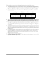
1. This equipment complies with Part 68 of the FCC rules. On the bottom of the equipment housing
is a label that shows the FCC registration number and Ringer Equivalence Number (REN) for this
equipment, if applicable. If required, this information must be given to the telephone company.
2. The following information may be required when applying to the local telephone company for
leased line facilities.
Service Type
3.
4.
5.
6.
7.
8.
REN/SOC
FIC
USOC
!"#
$
%
$ !"#
An FCC compliant telephone cord with a modular plug may be provided with this equipment. This
equipment is designed to be connected to the telephone network or premises wiring using a compatible modular jack, which is FCC Part 68 compliant. See installation instructions for details.
If this equipment causes harm to the telephone network, the telephone company may temporarily
discontinue service. If possible, advance notification is given; otherwise, notification is given as
soon as possible. The telephone company will advise the customer of the right to file a complaint
with the FCC.
The telephone company may make changes in its facilities, equipment, operations, or procedures that
could affect the proper operation of this equipment. If this happens, the telephone company will provide advance notification and the opportunity to make the necessary modifications to maintain uninterrupted service.
If experiencing difficulty with this equipment, please contact ADTRAN for repair and warranty information. If the equipment is causing harm to the network, the telephone company may request this
equipment to be disconnected from the network until the problem is resolved or it is certain that the
equipment is not malfunctioning.
This unit contains no user serviceable parts.
The FCC recommends that the AC outlet to which equipment requiring AC power is to be installed
is provided with an AC surge arrester.
7
%%
This equipment has been tested and found to comply with the limits for a Class A digital device, pursuant to Part 15 of the FCC Rules. These limits are designed to provide reasonable protection against
harmful interference when the equipment is operated in a commercial environment. This equipment
generates, uses, and can radiate radio frequency energy and, if not installed and used in accordance
with the instruction manual, may cause harmful interference to radio frequencies. Operation of this
equipment in a residential area is likely to cause harmful interference in which case the user will be
required to correct the interference at his own expense.
Shielded cables must be used with this unit to ensure compliance with Class A FCC limits.
Change or modifications to this unit not expressly approved by the party responsible for
compliance could void the user’s authority to operate the equipment.
This digital apparatus does not exceed the Class A limits for radio noise emissions from digital apparatus as set out in the interference-causing equipment standard entitled “Digital Apparatus," ICES-003
of the Department of Communications.
Cet appareil nuerique respecte les limites de bruits radioelectriques applicables aux appareils numeriques de Class A prescrites dans la norme sur le materiel brouilleur: "Appareils Numeriques," NMB003 edictee par le ministre des Communications.
8
)
Notice: The Canadian Industry and Science Canada label identifies certified equipment. This certification means that the equipment meets certain telecommunications network protective, operational, and
safety requirements. The Department does not guarantee the equipment will operate to the user’s satisfaction.
Before installing this equipment, users should ensure that it is permissible to be connected to the facilities of the local telecommunications company. The equipment must also be installed using an acceptable methods of connection. In some cases, the company’s inside wiring associated with a single line
individual service may be extended by means of a certified connector assembly (telephone extension
cord). The customer should be aware that compliance with the above limitations may not prevent degradation of service in some situations.
Repairs to certified equipment should be made by an authorized Canadian maintenance facility designated by the supplier. Any repairs or alterations made by the user to this equipment, or equipment
malfunctions, may give the telecommunications company cause to request the user to disconnect the
equipment.
Users should ensure for their own protection that the electrical ground connections of the power utility, telephone lines and internal metallic water pipe system, if present, are connected together. This
precaution may be particularly important in rural areas.
Users should not attempt to make such connections themselves, but should contract the
appropriate electric inspection authority, or an electrician, as appropriate.
The Load Number (LN) assigned to each terminal device denotes the percentage of the total load to be
connected to a telephone loop which is used by the device, to prevent overloading. The termination on
a loop may consist of any combination of devices subject only to the requirement that the total of the
Load Numbers of all devices does not exceed 100.
9
)*
ADTRAN warrants that for five (5) years from the date of shipment to Customer, all products manufactured by ADTRAN will be free from defects in materials and workmanship. ADTRAN also warrants that products will conform to the applicable specifications and drawings for such products, as
contained in the Product Manual or in ADTRAN's internal specifications and drawings for such products (which may or may not be reflected in the Product Manual). This warranty only applies if Customer gives ADTRAN written notice of defects during the warranty period. Upon such notice,
ADTRAN will, at its option, either repair or replace the defective item. If ADTRAN is unable, in a reasonable time, to repair or replace any equipment to a condition as warranted, Customer is entitled to a
full refund of the purchase price upon return of the equipment to ADTRAN. This warranty applies
only to the original purchaser and is not transferable without ADTRAN's express written permission.
This warranty becomes null and void if Customer modifies or alters the equipment in any way, other
than as specifically authorized by ADTRAN.
EXCEPT FOR THE LIMITED WARRANTY DESCRIBED ABOVE, THE FOREGOING CONSTITUTES
THE SOLE AND EXCLUSIVE REMEDY OF THE CUSTOMER AND THE EXCLUSIVE LIABILITY OF
ADTRAN AND IS IN LIEU OF ANY AND ALL OTHER WARRANTIES (EXPRESSED OR IMPLIED).
ADTRAN SPECIFICALLY DISCLAIMS ALL OTHER WARRANTIES, INCLUDING (WITHOUT LIMITATION), ALL WARRANTIES OF MERCHANTABILITY AND FITNESS FOR A PARTICULAR PURPOSE. SOME STATES DO NOT ALLOW THE EXCLUSION OF IMPLIED WARRANTIES, SO THIS
EXCLUSION MAY NOT APPLY TO CUSTOMER.
In no event will ADTRAN or its suppliers be liable to Customer for any incidental, special, punitive,
exemplary or consequential damages experienced by either Customer or a third party (including, but
not limited to, loss of data or information, loss of profits, or loss of use). ADTRAN is not liable for
damages for any cause whatsoever (whether based in contract, tort, or otherwise) in excess of the
amount paid for the item. Some states do not allow the limitation or exclusion of liability for incidental
or consequential damages, so the above limitation or exclusion may not apply to Customer.
10
+
+,
ADTRAN will replace or repair this product within five years from the date of shipment if the product
does not meet its published specification, or if it fails while in service.
A return material authorization (RMA) is required prior to returning equipment to ADTRAN. For service, RMA requests, training, or more information, see the toll-free contact numbers given below.
Please contact your local distributor, ADTRAN Applications Engineering, or ADTRAN Sales:
&'( (!$!)(!(!) *
+,
'
*
+,
,
-
Please contact your local distributor first. If your local distributor cannot help, please contact ADTRAN
Technical Support and have the unit serial number available.
-.!( '/
*+&-&
The Custom Extended Services (ACES) program offers multiple types and levels of service plans which
allow you to choose the kind of assistance you need. For questions, call the ACES Help Desk.
&$0'1
*+,2,
If ADTRAN Technical Support determines that a repair is needed, Technical Support will coordinate
with the Custom and Product Service (CAPS) department to issue an RMA number. For information
regarding equipment currently in house or possible fees associated with repair, contact CAPS directly
at the following number:
&3 4!
*+2,
11
Identify the RMA number clearly on the package (below address), and return to the following address:
!"#$%&
9:::::::::::::
,
The Enterprise Network (EN) Technical Training Department offers training on our most popular products. These courses include overviews on product features and functions while covering applications of
ADTRAN's product lines. ADTRAN provides a variety of training options, including customized training
and courses taught at our facilities or at your site. For more information about training, please contact
your Territory Manager or the Enterprise Training Coordinator.
12
- (!(!).!
*
+,56,
- (!(!)7 6
*+2,
- (!(!)4 ('
(!(!)8 " !4
Chapter 1 Overview.................................................................................................................................... 23
Product Overview.......................................................................................................................................... 23
TSU ESP Product Features ..................................................................................................................... 23
T1/FT1 Overview .................................................................................................................................... 24
Fractional T1 ..................................................................................................................................... 24
SNMP............................................................................................................................................................... 24
Network Manager.................................................................................................................................... 24
Agent ......................................................................................................................................................... 24
MIB............................................................................................................................................................. 25
Telnet ............................................................................................................................................................... 25
Dial Backup Operation.................................................................................................................................. 25
DBU Card Options................................................................................................................................... 26
4-wire Switched 56 DBU Card (P/N 1204001L1)........................................................................ 26
ISDN BRI DBU Card (P/N 1204004L1) ........................................................................................ 26
DCE Card (P/N 1204006L1)........................................................................................................... 26
Chapter 2 Installation................................................................................................................................. 27
Unpack, Inspect, Power Up .......................................................................................................................... 27
ADTRAN Shipments Include ................................................................................................................ 27
Customer Provides .................................................................................................................................. 28
Power Up .................................................................................................................................................. 28
Chapter 3 Operation ................................................................................................................................... 29
Front Panel Menu Structure ......................................................................................................................... 29
Main Menu................................................................................................................................................ 29
Main Menu Descriptions ................................................................................................................ 29
Status ........................................................................................................................................... 29
Configuration (Config)............................................................................................................. 29
Test............................................................................................................................................... 30
Utility (Util) ................................................................................................................................ 30
Basic Menu Travel ................................................................................................................................... 30
Enter ............................................................................................................................................ 30
Up Arrow.................................................................................................................................... 30
Down Arrow .............................................................................................................................. 30
Cancel.......................................................................................................................................... 30
Front Panel Menu Navigation ....................................................................................................... 31
Front Panel ...................................................................................................................................................... 32
LCD Window ............................................................................................................................. 32
Enter ............................................................................................................................................ 32
Shift.............................................................................................................................................. 32
Quick ........................................................................................................................................... 33
61200169L1-1
TSU ESP User Manual
13
Table of Contents
Cancel ..........................................................................................................................................33
Up and Down Arrows ..............................................................................................................33
LED Descriptions.......................................................................................................................33
Rear Panel........................................................................................................................................................ 34
DBU and Ethernet Card Slots................................................................................................................. 34
Network Interface Connection............................................................................................................... 35
V.35 Connector: DTE Data Connection/Primary DTE....................................................................... 35
Control Port .............................................................................................................................................. 36
VT 100 Terminal Connection And Operation ............................................................................................ 36
Chapter 4 Applications............................................................................................................................... 37
LAN Application With SNMP/Telnet Management................................................................................ 37
Minimum Configuration Requirements for SNMP/Telnet Access ......................................... 38
Interface.......................................................................................................................................38
IP Address ..................................................................................................................................38
Subnet Mask ...............................................................................................................................38
Gateway IP Address (if required) ...........................................................................................38
Special Features of this Application.............................................................................................. 38
Dial Backup Application ............................................................................................................................... 39
Entering Dial Backup Mode ................................................................................................................... 39
Operation During Critical Times................................................................................................... 39
"
.*
;"""
.*
<#""="'
.*
="'
""+
*.*
Operation During Noncritical Times ............................................................................................ 40
Weekend and Time of Day Lockout .......................................................................................40
Conditions for Returning to the T1 Circuit .......................................................................................... 40
Chapter 5 Status........................................................................................................................................... 41
TSU ESP Status Menu.................................................................................................................................... 41
NI PERF RPTS .......................................................................................................................................... 41
,&,#,=& .4
> .4
>,= .4
&,& .4
,& .4
8& .4
CURR ERR/ALM..................................................................................................................................... 42
/&" .4
&"
.4
'=
.4
;"""
.4
"
.0
" .0
%"
".0
=
%,
.0
#//"
.0
ERR/ALM HIST....................................................................................................................................... 43
"
!
( .0
/&" .0
&"
.0
'=
.0
;"""
.0
14
TSU ESP User Manual
61200169L1-1
Table of Contents
"
.0
" ..
%"
" ..
=
%,
..
#//"
..
DBU STATUS ........................................................................................................................................... 44
& ..
&& ..
%8&,&%8 ..
%8/&' ..
Chapter 6 Configuration Menu ................................................................................................................ 45
Configuration Menu ...................................................................................................................................... 45
Network (NI) ............................................................................................................................................ 45
=
.5
.5
;""
.5
?# .5
"&'
.5
Network Timing ........................................................................................................................ 46
DTE Timing ................................................................................................................................ 47
Internal Timing .......................................................................................................................... 47
%&' .2
&/% .2
?&$( .2
UNIT .......................................................................................................................................................... 49
"#
.)
# .)
.)
1*
"
1*
1*
'' 1*
"' 1*
PORT.......................................................................................................................................................... 51
15@5. 1+
" 1+
,?/A 14
&
14
9 14
14
&3"
&6 14
3
6 14
&3&(6 10
Inband ............................................................................................................................................... 53
DBU Module............................................................................................................................................. 54
Module-Specific Options -- BRI ISDN DBU Module (P/N 1204004L1) .................................. 55
%' 11
'" 11
&( 11
/
'3/6 11
&#'<
3&
$#
"6 11
%8!' 11
#'<
11
61200169L1-1
TSU ESP User Manual
15
Table of Contents
Module-Specific Options - 4-Wire Switched 56 DBU Module (P/N 1204001L1)................... 55
%8!' 11
#'<
15
Module-Specific Options - External DCE DBU Module (P/N 1204006L1) ............................. 56
15
#
(15
%'15
%' 15
/' 15
,<"!15
<"!15
%'"(1B
"(1B
("(1B
'
1B
Management ............................................................................................................................................. 58
Interface............................................................................................................................................. 58
Chain In Port .................................................................................................................................... 58
IP Address......................................................................................................................................... 59
Unit IP Address..........................................................................................................................59
Subnet Mask ...............................................................................................................................59
Gateway IP .................................................................................................................................59
IP Security...................................................................................................................................59
IP Filter Address ........................................................................................................................59
SNMP OPTIONS.............................................................................................................................. 59
Get Community .........................................................................................................................59
Set Community ..........................................................................................................................59
Trap Community .......................................................................................................................59
SNMP Traps ...............................................................................................................................59
Trap IP Address .........................................................................................................................60
Telnet Options .................................................................................................................................. 60
Telnet Password.........................................................................................................................60
Telnet Timeout ...........................................................................................................................60
Test Config ................................................................................................................................................ 60
Timeout (sec) .................................................................................................................................... 60
Answer Test ...................................................................................................................................... 61
Chapter 7 Utility Menu .............................................................................................................................. 63
UTIL ................................................................................................................................................................. 63
Time/Date................................................................................................................................................. 64
5.
5.
Editing the Time and Date .......................................................................................................64
Software Rev............................................................................................................................................. 64
LAN MAC Addr ...................................................................................................................................... 64
Fact Restore ............................................................................................................................................... 64
Unit ID ....................................................................................................................................................... 64
Set Passcode .............................................................................................................................................. 65
Keypad....................................................................................................................................................... 65
DBU Utilities............................................................................................................................................. 65
Framer/LIU .............................................................................................................................................. 65
Type/Revision ................................................................................................................................. 65
T1 Rx Level ....................................................................................................................................... 65
Product Rev............................................................................................................................................... 65
16
TSU ESP User Manual
61200169L1-1
Table of Contents
Serial Number .......................................................................................................................................... 65
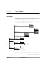
Chapter 8 Test Menu .................................................................................................................................. 67
Test Menu........................................................................................................................................................ 67
Network Tests .......................................................................................................................................... 68
/"/< 52
/< 52
/ 52
#(" 52
/< 52
/< 52
=+/< 52
&=///% 52
C<//% 52
&=/#/% 52
C=/#/% 5)
#
5)
No Pattern................................................................................................................................... 69
1++$&* 5)
""D
5)
"" 5)
QRSS Active DS0s ..................................................................................................................... 69
#
'" 5)
Run Self-test.............................................................................................................................................. 69
Port Tests................................................................................................................................................... 70
,/< B*
/< B*
DBU Tests.................................................................................................................................................. 70
%8/< B*
B*
%8'" B*
Chapter 9 Testing and Troubleshooting................................................................................................. 71
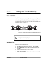
Test Overview................................................................................................................................................. 71
Initiating a Test......................................................................................................................................... 71
Testing Example .............................................................................................................................. 72
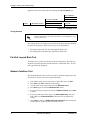
Far End Looped Back Test...................................................................................................................... 72
Network Interface Test............................................................................................................................ 72
Displaying the Test Pattern .................................................................................................................... 73
Appendix A Network Pinouts ................................................................................................................... 75
Appendix B
DTE Data Rate Chart........................................................................................................... 81
Appendix C Glossary .................................................................................................................................. 83
61200169L1-1
TSU ESP User Manual
17
Table of Contents
18
TSU ESP User Manual
61200169L1-1
Figure 1-1. TSU ESP Point-to-Point Application......................................................................................
Figure 3-1. Main Menu LCD Display ........................................................................................................
Figure 3-2. Example of Basic Menu Navigation.......................................................................................
Figure 3-3. TSU ESP Front Panel ................................................................................................................
Figure 3-4. DSU IV ESP Rear View ............................................................................................................
Figure 4-1. SLIP/PPP LAN Application with SNMP/Telnet Management........................................
Figure 4-2. Ethernet LAN Application with SNMP/Telnet Management...........................................
Figure 4-3. Dial Backup Application..........................................................................................................
Figure 5-1. Status Menu ...............................................................................................................................
Figure 6-1. Network Configuration Menu Tree .......................................................................................
Figure 6-2. Network Timed Clock Source.................................................................................................
Figure 6-3. DTE Clock Source .....................................................................................................................
Figure 6-4. Internal Clock Source ...............................................................................................................
Figure 6-5. Unit Configuration Menu Tree ...............................................................................................
Figure 6-6. Port Configuration Menu Tree ...............................................................................................
Figure 6-7. Inband Remote Configuration ................................................................................................
Figure 6-8. DBU Module Configuration Menu Tree ...............................................................................
Figure 6-9. Management Configuration Menu Tree................................................................................
Figure 6-10. Test Config Menu Tree.............................................................................................................
Figure 7-1. Utility Menu Tree......................................................................................................................
Figure 8-1. Complete Test Menu ................................................................................................................
Figure 9-1. Normal Operation Before Initiating Loopback Test ............................................................
Figure 9-2. Initiating a Test..........................................................................................................................
61200169L1-1
TSU ESP User Manual
23
29
31
32
34
37
38
39
41
45
47
47
48
49
51
53
54
58
60
63
67
71
72
19
List of Figures
20
TSU ESP User Manual
61200169L1-1
Table 3-1.
Table 6-1.
Table B-1.
Front Panel LED Descriptions ................................................................................................ 33
Normal Mode Operation......................................................................................................... 53
DTE Data Rate Chart................................................................................................................ 81
61200169L1-1
TSU ESP User Manual
21
List of Tables
22
TSU ESP User Manual
61200169L1-1
Chapter 1
Overview
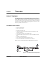
PRODUCT OVERVIEW
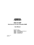
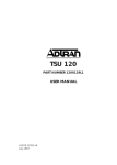
The ADTRAN TSU ESP is a full-featured T1/FT1 Data Service/Channel
Unit (DSU/CSU) with an integral embedded SNMP agent and optional dial
backup (DBU) capabilities. It provides an interface between T1 or Fractional
T1 service and the customer's data terminal equipment (DTE). The TSU ESP
provides access to traditional dedicated point-to-point T1 services as well as
frame relay, SMDS, and ATM services.
TSU ESP Product Features
E
&" 01,
E
-15
-5.
E
,<&#"
E
"
36
$&/#
###&#
+**
"'
E
"/
&#
"
E
",&#%8
"'.
&15"%-
"
,
E
'
'""<'
E
("<'"'
E
&'
#$@'
"
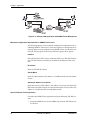
Figure 1-1 shows a typical point-to-point application for the TSU ESP.
Figure 1-1. TSU ESP Point-to-Point Application
61200169L1-1
TSU ESP User Manual
23
Chapter 1. Overview
T1/FT1 Overview
T1 is a digital service that service providers deliver to the user over two pairs
of wires. The signal operates at 1.544 mega bits per second (Mbps) and is
usually extended by repeaters that are installed about every mile after the
first 6000 feet. The T1 signal is divided into 24 time slots, or digital signal level zeros (DS0s), which operate at 64 kilobits per seconds (kbps). Each time
slot is occupied by digitized voice or data.
T1 signals originally used a type of framing known as D4 Superframe which
identifies how the T1 is multiplexed. Extended Superframe (ESF) is an enhancement of that framing format. ESF provides a non-disruptive means of
full-time monitoring on the digital facility. Service providers originally used
ESF to monitor the performance of their service offering. Since the introduction of ESF, equipment that is installed in private networks can also provide
the same performance information to the user.
Fractional T1
Fractional T1 (FT1) provides less than a full T1 circuit between two points.
Most carriers offer fractional T1 in increments of 56 or 64 kbps. The network
allows multiple users to share the same inter-office T1 bandwidth.
FT1 remains almost exclusively an inter-exchange carrier (IXC) service. Local exchange carriers (LECs) typically do not offer FT1, so the user’s proximity to the IXC’s point-of-presence (POP) is key in the savings that fractional
T1 offers.
SNMP
Simple Network Management Protocol (SNMP) broadly refers to the message protocols used to exchange information between the network and the
managed devices, as well as to the structure of network management data
bases. SNMP has three basic components: a network manager, an agent, and
a Management Information Base (MIB).
Network Manager
The Network Manager is a control program that collects, controls, and presents data pertinent to the operation of the network devices. It resides on a
network management station.
Agent
The Agent is a control program that resides in each network device connected. This program responds to queries and commands from the network
manager and returns requested information or invokes configuration changes the manager initiates.
24
TSU ESP User Manual
61200169L1-1
Chapter 1. Overview
MIB
The MIB is an index to the organized data within a network device. It defines
the operation parameters that can be controlled or monitored.
The TSU ESP supports the MIB-II standard, RFC 1213, RFC 1406, and ADTRAN Enterprise Specific MIB. MIB files are available in the post-sales support section of the ADTRAN web page at: http://www.adtran.com.
The TSU ESP's embedded SNMP feature allows a network manager to access and control the unit through either a device running SLIP or async PPP
protocol (connected to the CONTROL port of the TSU ESP) or through a
LAN. LAN connection requires the optional ESP ethernet card (P/N
1204005L1). This card provides a 10BaseT ethernet interface to the LAN.
TELNET
Telnet provides a password-protected, remote login facility to the TSU ESP.
Telnet allows a user on a network manager to control the TSU ESP through
the optional 10BaseT ethernet LAN modual (P/N 1204005L1.) See VT 100
Terminal Connection And Operation on page 36for more information.
DIAL BACKUP OPERATION
The TSU ESP supports dial backup of fractional T1 circuits. For T1 backup,
the TSU ESP enters dial backup based on physical line faults. During dial
backup, the TSU ESP monitors the main line integrity and drops the dial
backup call when the main line is restored.
The 4-wire SW56 DBU card is compatible with AT&T Accunet and Sprint
SW56 type services.The ISDN 2B+D card supports a U-interface to the Basic
Rate ISDN and is compatible with LUCENT 5ESS, DMS 100, and National
ISDN TSU ESPs.
The TSU ESP’s unique DBU cards are field-installable by the customer. See
the section DBU and Ethernet Card Slots on page 34 for information on installing DBU cards. Also see the chapterDBU Module on page 54for information
on configuring DBU options.
The backup options are described in the following sections. Contact the local
telco provider to determine which services are available in your area.
61200169L1-1
TSU ESP User Manual
25
Chapter 1. Overview
DBU Card Options
4-wire Switched 56 DBU Card (P/N 1204001L1)
This dial-up 4-wire SW56 card allows you to pay for data connection only
for the time the unit is active. The regional operating companies provide the
4-wire local loop service to SW56 customers.
ISDN BRI DBU Card (P/N 1204004L1)
2B+D Basic Rate ISDN service provides backup over an ISDN circuit. 2B+D
BRI service provides the customer with a switched 112/128 kbps circuit.
When placing a call from an ISDN DBU card to a switched 4-wire unit,
append a #3 (requesting a digital data circuit) to the end of the phone number
to ensure a reliable connection.
DCE Card (P/N 1204006L1)
The DCE DBU card allows you to use an existing piece of data communication hardware to back up the T1/FT1 network. The existing S4W unit, ISDN
unit, or modem should be configured to dial when DTR is raised by the DCE
DBU card.
The pinouts for the DBU cards are available in Network Pinouts on page 75 .
26
TSU ESP User Manual
61200169L1-1
Chapter 2
Installation
UNPACK, INSPECT, POWER UP
Carefully inspect the TSU ESP for shipping damages. If damage is suspected, file a claim immediately with the carrier and contact ADTRAN Customer
Service. If possible, keep the original shipping container for use in shipping
the TSU ESP for repair or for verification of damage during shipment.
ADTRAN Shipments Include
The following items are included in ADTRAN shipments of the TSU ESP:
E
&8,&#'
E
+/
<"F2'"
2'"
3+16
E
&'
$
(
<"F2'"
2'"
356
E
#
F2"'"
"%41
"@&/#@###
E
/<"'
E
&8,&#
E
&8,&#G'&
H'
E
="#
The ADTRAN TSU ESP MIB is available from ADTRAN in the
support section of the ADTRAN web page at www.adtran.com.
The following items are included in ADTRAN’s shipments of ESP DBU
cards:
61200169L1-1
E
,&#%8
E
2'"
2'"
<"
.
&15
&"<'
TSU ESP User Manual
27
Chapter 2. Installation
Customer Provides
The customer must provide the appropriate DTE cable to connect to the TSU
ESP. The TSU ESP requires a male V.35 interface cable when connecting the
unit to external data service equipment (i.e., router).
For SNMP management, the customer must provide access to the TSU ESP
either through a SLIP port, Async PPP port (requires a male 25-pin D-type
connector), or a 10BaseT ethernet port (requires an ADTRAN ESP ethernet
card installed in the TSU ESP). See Network Pinouts on page 75 for the pin assignments for the control port (for SLIP and Async PPP) and the optional
10Base T Ethernet LAN Module port (P/N 1204005L1).
Power Up
The TSU ESP is provided with a captive 8-foot power cord, terminated by a
three-prong plug which connects to a grounded 115 VAC power receptacle.
Power to the TSU ESP must be provided from a grounded 115 VAC, 60
Hz receptacle.
28
TSU ESP User Manual
61200169L1-1
Chapter 3
Operation
FRONT PANEL MENU STRUCTURE
The TSU ESP uses a multilevel menu approach to access its many features.
All menu operations are displayed in the LCD window or the terminal.
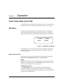
Main Menu
The following section briefly describes the Main menu's four branches,
which are displayed on the front panel LCD (see Figure 3-1). Detailed
information is provided in the individual chapters for each menu branch.
.
,,/
0.12%3
4./,) .,
,
Figure 3-1. Main Menu LCD Display
The opening menu is the access point to all other operations. Each Main
menu item has several functions and submenus to identify and access
specific parameters.
Main Menu Descriptions
The branches of the front panel Main menu are divided into options for
STATUS, TEST, CONFIGURATION (CONFIG), and UTILITY (UTIL).
Status
STATUS menus display all relevant information for the network and DTE
interfaces. The system returns to the STATUS display when idle. For more
information, see Chapter 5, Status on page 41.
Configuration (CONFIG)
Use CONFIGURATION menus to select network and DTE operating
parameters, configure testing and dialing options, select management
functions, and configure unit utilities. See Chapter 6, Configuration Menu on
page 45, for more information.
61200169L1-1
TSU ESP User Manual
29
Chapter 3. Operation
Test
Use TEST menus to control local and remote testing. Select LOCAL or REMOTE
testing, and the type of test and test pattern when required. For more
information, see Chapter 8, Test Menu on page 67.
Utility (UTIL)
The UTILITY menu displays and sets system parameters. See Chapter 7,
Utility Menu on page 63 for detailed information on the available options.
Basic Menu Travel
Four function keys on the left side of the TSU ESP keypad allow the various
menu branches to be entered, exited, and scrolled through. The four
function keys are defined below.
Enter
Selects a displayed item.
Up Arrow
Scrolls up the submenu items.
Down Arrow
Scrolls down the submenu items.
Cancel
Exits (back one level) from the current branch of the menu.
To choose a menu item, press the corresponding number or alpha character
on the keypad (press Shift to activate alpha characters). The item flashes on
and off to show it is the currently selected (active) choice. Press the up or
down arrow keys to scroll through the available menu items. Press Enter to
select the flashing item.
30
TSU ESP User Manual
61200169L1-1
Chapter 3. Operation
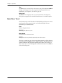
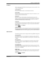
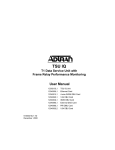
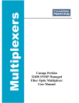
Front Panel Menu Navigation
Some Management menus require that you enter letters rather than
numbers. When configuring the unit using the front panel, you must follow
special steps in order to enter letters. The following example shows how to
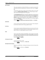
enter the Telnet password.
Step
1
Action
From the main menu, press 2, then Enter. Press 5, then Enter.
2
Press 5, then Enter to select TELNET OPTIONS from the
Management Menu.
3
Press 1, then Enter to select TELN PASSWORD.
4
Press Enter to begin editing. The cursor appears as an underscore .
5
Use the up and down arrow keys to scroll to the appropriate
letter.
6
Once the desired letter is displayed, press Enter. A block cursor appears in the next field.
7
Repeat this procedure until all letters have been entered.
8
When password entry is complete, press Enter. The cursor
returns to the beginning of the option text.
1)NETWORK
2)CONFIG
2)UNIT
1)INTERFACE
3)PORT
2)CHAIN IN PORT
4)DBU MODULE
3)IP ADDRESS
5)MANAGEMENT
4)SNMP OPTIONS
1)TELNET PASSWORD
6)TEST CONFIG
5)TELNET OPTIONS
2)TELN TIMEOUT
Figure 3-2. Example of Basic Menu Navigation
61200169L1-1
TSU ESP User Manual
31
Chapter 3. Operation
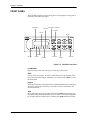
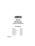
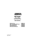
FRONT PANEL
The TSU ESP faceplate is shown in Figure 3-3. Descriptions of each part of
the front panel follow the figure.
LCD Window
Up and Down Arrow Keys
ALM LED
Enter Key
RD LED
Keypad
RS LED
TD LED
CS LED
ERR LED
Cancel Key
Quick Key
Shift Key
Figure 3-3. TSU ESP Front Panel
LCD Window
Displays menu items and messages in 2 lines by 16 characters.
Enter
Selects active menu items. To select a menu item, press the number of the
item. The menu item flashes, indicating it is activated. Press Enter to select
the menu item.
Keypad
The keypad contains dual-function keys numbered 0 through 9 with alpha
characters A through F. These keys are used to activate menu items and
enter information.
Shift
Enter alpha characters by pressing and releasing Shift before pressing the
key representing the desired character. To activate a menu item designated
by an alpha character rather than a number, press Shift and then the letter.
32
TSU ESP User Manual
61200169L1-1
Chapter 3. Operation
The menu item flashes, indicating which parameter is activated. Press Enter
to select the item.
If a key is pressed without using Shift, the numbered item becomes active
instead of the alpha item.
Quick
During most operations, the Quick key returns the display to the Main
menu. During a test, the Quick key returns to the top of the TEST menu. In
SW56 operations, if the unit is not in test, the Quick key returns to the DIAL
menu.
Cancel
Pressing the Cancel key stops the current activity and returns to the
previous menu. Repeat until the desired menu level is reached.
Up and Down Arrows
Up and down arrows scroll through the submenu items available in the
current menu.
LED Descriptions
The TSU ESP has seven LED indicators: RS, CS, TD, RD, ERR, ALM, and
TST. These LEDs are described in Table 3-1.
Table 3-1. Front Panel LED Descriptions
LED
61200169L1-1
Description
RS: Request to Send
Reflects the status of the request to send pin of the
DTE interface.
CS: Clear to Send
Reflects the status of the clear to send pin of the DTE
interface.
TD: Transmit Data
This LED is active when data is transmitted from the
DTE.
RD: Receive Data
This LED is active when data is received from the network.
ERR: Error Indicator
This LED is active when an error, such as a BPV or
CRC error, occurs on the network.
ALM: Alarm Indication
This LED activates whenever an alarm condition exists.
Alarm conditions include:
Network Signal Loss
No Frame Synchronization
Remote Alarm Indication
TST: Test Mode
This LED is on whenever the unit is in test mode.
TSU ESP User Manual
33
Chapter 3. Operation
REAR PANEL
The rear panel contains a DTE connector which provides primary channel
V.35. An 8-pin telco jack, a control chain-in and chain-out port, a captive
power cord, and a power switch are also located on the rear panel. Pin
assignments for these connectors are listed in Appendix A, Network Pinouts.
The TSU ESP rear panel is shown in Figure 3-4.
Item
DBU Interface
Function
ESP DBU card slot
LAN Interface
ESP Ethernet card slot
Network
Connects to dedicated circuit
Control
Connects to a VT 100 terminal or a device
running SLIP or async PPP protocol
V.35
High speed DTE interface
Power Switch
Turns power on or off
115 VAC Connection Power cord connection
Figure 3-4. DSU IV ESP Rear View
DBU and Ethernet Card Slots
Remove power from the unit before installing or removing ESP option
cards.
The TSU ESP rear panel has two card slots for the installation of dial backup
and ethernet cards. To insert cards, perform the following procedure:
1.
34
Remove power from the TSU ESP.
TSU ESP User Manual
61200169L1-1
Chapter 3. Operation
2.
Slide the card into the corresponding rear slot until the card panel is
flush with the TSU ESP chassis.
3.
Push card locks in (until they click) to secure the card and ensure
proper installation.
Card slots are keyed to prevent improper installation (i.e., putting a
DBU card into the ethernet slot).
Network Interface Connection
The TSU ESP has an 8-position modular jack labeled NETWORK. The
Network Interface (NI) port complies with the applicable ANSI and AT&T
standards and has the following features:
•
Alternate mark inversion (AMI) or binary 8 zero suppression (B8ZS)
coding
•
Automatic or manual line build-out
•
Auto detect or manual settings for D4 or ESF framing
•
Network performance monitoring and reporting
•
Test loopbacks by local and remote
•
Extensive self-testing
The pinout for this connector is listed in Appendix A, Network Pinouts on
page 75.
V.35 Connector: DTE Data Connection/Primary DTE
The primary DTE should be connected to the V.35 DTE connector. The
maximum cable length recommended for the V.35 is 100 feet.
•
Data rates: N*56K or N*64K, where N=1 to 24 (DS0s)
•
Invert data feature
•
A V.35 interface
•
Standard V.35 connector
•
Test loopbacks with 511 pattern generation and check
•
Extensive self-testing
The pin assignments for the connectors are listed in Appendix A, Network
Pinouts on page 75.
To prevent possible radio frequency interference emissions, a shielded cable is required.
61200169L1-1
TSU ESP User Manual
35
Chapter 3. Operation
Control Port
The TSU ESP has an 8-position modular jack labeled CONTROL. The control
port provides connection to a VT 100 EIA-232 compatible interface, a device
running SLIP protocol, or a device running Async PPP protocol. An 8-foot
adapter cable and connector provide a standard DB-25 EIA-232 interface.
Features of the control port include:
•
•
•
RS-232 input from a personal computer (PC) or a modem for control of
the TSU ESP
Chain input/output from another TSU ESP
Up to 9600 baud operation
See Appendix A, Network Pinouts for the control port’s pin assignments.
The control port also functions as the SLIP or Async PPP port when
configured for SNMP management. The pinouts are identical when
operating in an SNMP management mode.
Connect to the Control port using the following settings: 8 data bits, no
parity bits, 1 stop bit.
VT 100 TERMINAL CONNECTION AND OPERATION
To control the TSU ESP using a VT 100 terminal, perform the following
procedure:
1.
Select a terminal interface through the front panel. Select 2)CONFIG>
5)MANAGEMENT>1)INTERFACE >CHAIN IN.
2.
Set the DATA RATE to match the VT 100 terminal by choosing
2)CONFIG> 2)UNIT>1)CONTROL PORTS >3)DATA RATE.
3.
Using the provided VT 100 terminal adapter cable, connect the COM
port of a VT 100 compatible terminal or equivalent to the 8-pin modular
jack labeled CONTROL IN on the rear of the TSU ESP. This connection is
used for both local and remote configuration.
4.
Establish the connection and press <Ctrl-A><Ctrl-P><Ctrl-T> or <CtrlP><Ctrl-T><Ctrl-T> until the TERMINAL MENU appears.
5.
Make selections by entering the number corresponding to the chosen
parameter. Press ESC to return to the previous screen.
The TSU ESP VT 100 interface is only available when the unit is configured
for ADLP on the chain-in port and chain-in is selected as the management
interface. This requirement prevents a conflict that would exist if you
opened a telnet session over the ethernet interface at the same time that a
VT 100 session was active on the chain-in port (that is, two terminal modes
open simultaneously).
When establishing a Telnet session, the system prompts for a password. The
default password is adtran. This password can be modified through the
Management menu. See Management on page 58 for more information.
36
TSU ESP User Manual
61200169L1-1
Chapter 4
Applications
This chapter provides examples of some common TSU ESP applications. The
examples include LAN applications with both SLIP/PPP and ethernet management and a dial backup application.
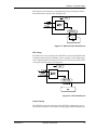
LAN APPLICATION WITH SNMP/TELNET MANAGEMENT
The TSU ESP can be managed through an established Telnet session or an
SNMP-based network manager like HP Openview, IBM Netview, or SunNet
Manager.
The ADTRAN TSU ESP MIB is available in the support section of the
ADTRAN web page at www.adtran.com.
SNMP and Telnet management are provided by one of the following interfaces:
•
A device (e.g., a router) running SLIP protocol. Connection is made
through the TSU ESP's control port. See Figure 4-1.
•
A device (e.g., a router) running Async PPP protocol. Connection is
made through the TSU ESP's control port. See Figure 4-1.
•
A LAN. Connection is made through the optional 10BaseT ethernet
interface provided on the ESP ethernet card (P/N 1204005L1). See
Figure 4-2.
A
1
TD1 RD1
TD2 RD2
TDN RDN ALM
/TST
B
2
D
4
7
TD1 RD1
TD2 RD2
TDN RDN ALM
/TST
D
4
8
7
8
0
C
3
ADD
9
QUICK
#
F
6
PREV
DELE
TE
0
C
3
E
5
NEXT
SHIFT
DSU IV ESP
F
6
PREV
DELE
TE
B
2
DSU IV ESP
E
5
NEXT
SHIFT
A
1
ADD
9
QUICK
#
Figure 4-1. SLIP/PPP LAN Application with SNMP/Telnet Management
61200169L1-1
TSU ESP User Manual
37
Chapter 4. Applications
A
1
TD1 RD1
TD2 RD2
TDN RDN ALM
/TST
B
2
D
4
7
TD1 RD1
TD2 RD2
TDN RDN ALM
/TST
B
2
D
4
8
7
8
0
ADD
9
QUICK
#
F
6
PREV
DELE
TE
0
C
3
E
5
NEXT
SHIFT
C
3
F
6
PREV
DELE
TE
DSU IV ESP
DSU IV ESP
E
5
NEXT
SHIFT
A
1
ADD
9
QUICK
#
Figure 4-2. Ethernet LAN Application with SNMP/Telnet Management
Minimum Configuration Requirements for SNMP/Telnet Access
The following options are the minimum configuration requirements for establishing SNMP or Telnet access. Once these options are configured, the remaining options may be configured using SNMP/Telnet. See the menu tree
in Figure 6-9 on page 58 for the front panel menu path to these options.
Interface
Select SLIP Control, PPP Control, or Ethernet LAN as the TSU ESP interface
type. The ESP ethernet card must be installed for the Ethernet LAN selection.
IP Address
Enter the TSU ESP IP address.
Subnet Mask
Enter the subnet number. This address is available from the network administrator.
Gateway IP Address (if required)
Enter the Gateway node IP address. This address is necessary only if the TSU
ESP and the network manager are connected through a Gateway node. This
address is available from the network administrator.
Special Features of this Application
Customize the SNMP/Telnet application using the following TSU ESP features:
•
38
Designate SNMP hosts to receive SNMP traps from the TSU ESP (one to
five entries).
TSU ESP User Manual
61200169L1-1
Chapter 4. Applications
•
Secure the TSU ESP by limiting SNMP network management access. If
enabled, the TSU ESP only responds to a user-configured list of SNMP
network managers (one to five entries).
Configure these options through the Management portion of the Configuration menu. See Management on page 58for more information.
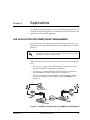
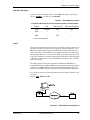
DIAL BACKUP APPLICATION
The TSU ESP provides point-to-point connection to the network. With one
of the ESP DBU option cards installed, the unit is capable of dial backup, allowing the unit to dial around a failed network. See Figure 4-3.
With the DBU options, configure the unit to:
•
Enter DBU under specific primary network conditions.
•
Lock out DBU over the weekend and/or at specified times of the day.
•
Dial a specified number when a DBU activation condition is detected.
A
1
TD1 RD1
TD2 RD2
TDN RDN ALM
/TST
B
2
D
4
7
8
0
A
1
B
2
D
4
7
8
0
9
C
3
F
6
PREV
DELE
TE
ADD
QUICK
#
DSU IV ESP
E
5
NEXT
SHIFT
C
3
F
6
PREV
DELE
TE
TD1 RD1
TD2 RD2
TDN RDN ALM
/TST
DSU IV ESP
E
5
NEXT
SHIFT
ADD
9
QUICK
#
Figure 4-3. Dial Backup Application
Entering Dial Backup Mode
When a condition for entering dial backup mode is detected, the ALARM LED
turns on and the buzzer sounds. The buzzer alternates between 30 seconds
on and 30 seconds off unless the DDS line is restored or it is disabled by using the Quick key and selecting TURN OFF BEEP. See the section Front Panel
on page 32 for more information on the Quick key.
Operation During Critical Times
The TSU ESP allows the user to select the conditions that initiate the dial
backup mode. The factory default enables DBU mode upon detection of
these conditions. The following four conditions can cause a TSU ESP to enter
dial backup mode:
61200169L1-1
TSU ESP User Manual
39
Chapter 4. Applications
A Red Alarm condition occurs when the TSU ESP starts receiving major errors from the T1/FT1 network. Conditions that will cause a Red Alarm include LOSS OF SIGNAL (LOS) or OUT OF FRAME (OOF).
5'
A yellow alarm condition occurs when the remote
TSU ESP receives major errors from the T1/FT1 network.
$%
In situations where the FDL is not available, you can use inband polling to
verify the integrity of the T1/FT1 network. Inband polling is automatically
enabled when the inband option is set to on. In order for inband polling to
work properly, both the local and remote TSU ESPs must have the inband
option set to on
%+6
The network will usually generate this condition to indicate that some device (or devices) in the network are inoperative. This condition is only used
as a dial backup condition if the BACKUP ON: NET/DATA FAIL option is selected.
Operation During Noncritical Times
The TSU ESP may be configured not to enter dial backup mode if data terminal ready (DTR) is low. This feature prevents the TSU ESP from entering
dial backup during noncritical times such as nights and weekends.
For more information, see DBU Module on page 54.
Weekend and Time of Day Lockout
The TSU ESP may be configured not to enter dial backup mode based upon
the time of day or weekend status. This protects the customer from being
charged for a switched call during off hours should the dedicated circuit fail.
See on page 56 for more information.
Conditions for Returning to the T1 Circuit
The TSU ESP automatically returns to the T1/FT1 circuit when the backup
condition (red alarm, yellow alarm, data failure, or inband poll failure) is
corrected. The TSU ESP can be configured to wait a specified amount of time
before the network connection is restored.
See on page 57 for more detailed information.
40
TSU ESP User Manual
61200169L1-1
Chapter 5
Status
TSU ESP STATUS MENU
The STATUS menu displays the status of the TSU ESP operation. See Figure
5-1.
! "
! " #
Figure 5-1. Status Menu
NI PERF RPTS
The NETWORK INTERFACE PERFORMANCE REPORTS menu displays the user
copy of the performance data. The TSU ESP maintains this performance data
on the network in compliance with ANSI T1.403 and AT&T document
TR54016. The data displayed is data accumulated over the last 15 minutes
and over the last 24 hours.
61200169L1-1
TSU ESP User Manual
41
Chapter 5. Status
You cannot edit these fields, only clear them. Only the user copy of performance data is cleared.
The available options are listed below:
,%2,
Reset local performance counters
78
Percentage of available seconds
7%
Percentage of error free seconds
Number of severely errored seconds
Number of errored seconds
/
Number of unavailable seconds
Continue with standard operating procedures to exit the display. Since the
TSU ESP only clears the user’s copy of performance data, the data displayed here might be different from the data being sent to the network as
performance report message (PRM) data.
CURR ERR/ALM
TheCURRENT ERROR/ALARM MENU displays currently active and inactive errors and alarms. Use the up and down arrows to access the complete display
of the errors/alarms that are currently active. You can review the following
alarms and errors.
)
No pulses received at NI.
Unframed All-Ones received at NI.
1%
No framing pattern sync at NI.
5'
Receiving yellow alarm pattern from NI.
42
TSU ESP User Manual
61200169L1-1
Chapter 5. Status
Loss of signal/out of frame (LOS/OOF) causing red alarm at NI.
8
Cyclic redundancy check (CRC) errors in ESF, or bipolar violations (BPVs)
in Superframe Format (SF) were received at NI Bipolar Violations BPVs in
SF or ESF.
"8
Bipolar violations received at NI.
%"
Frame Bits received incorrectly at NI.
))
Unable to sync up to selected clock.
ERR/ALM HIST
The ERROR/ALARM HISTORY menu displays the history of errors and alarms.
If an alarm has occurred since the lastCLEAR HISTORY selection, the menu is
ACTIVE. If the condition has not occurred then, the menu is INACTIVE. These
conditions are the same as for the CURR ERR/ALMsubmenu except that
these are HISTORY ALARM/ERRORS instead of CURRENT ALARM/ERRORS.
9
)
No pulses received at NI.
Unframed All-Ones received at NI.
1%
No framing pattern sync at NI.
5'
Receiving yellow alarm pattern from NI.
Loss of signal/out of frame (LOS/OOF) causing red alarm at NI.
61200169L1-1
TSU ESP User Manual
43
Chapter 5. Status
8
Cyclic redundancy check (CRC) errors in ESF, or bipolar violations (BPVs)
in Superframe Format (SF) were received at NI Bipolar Violations BPVs in
SF or ESF.
"8
Bipolar violations received at NI.
%"
Frame Bits received incorrectly at NI.
))
Unable to sync up to selected clock.
DBU STATUS
The DBU STATUS menu only appears when a dial backup module is installed in the TSU ESP.
,
Displays the status of DCD, DTR, and DSR on the DBU card.
,
,
Displays the status of RTS, CTS, and RI on the DBU card.
"/
"/
Displays the number of seconds that the TSU ESP has been in dial backup
mode and indicates whether or not the unit is currently in dial backup mode.
You can clear the second counter by pressing on the keypad.
"/)
Available only when either the ISDN or S4W card is installed. This message
reports the status of the ISDN or switches 4-wire line.
DBU Line Status is not available when an external DCE DBU
card is installed.
44
TSU ESP User Manual
61200169L1-1
Chapter 6
Configuration Menu
The CONFIGURATION menu sets the TSU ESP operational configuration, including all of the network interface parameters, and the allocation of the
DS0s and the port parameters.
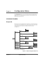
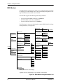
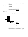
CONFIGURATION MENU
Network (NI)
This menu accesses the configuration of parameters associated with the network interface in the TSU ESP. There are eight submenu items that include
setting the format, the line build out (LBO), and the clock source
(see Figure 6-1).
AUTO
ESF
1)FORMAT
D4
1)NETWORK
B8ZS
2)CODE
AMI
ENAB
3)YEL ALARM
DISA
OFF
2)CONFIG
4)XMIT PRM
ON
NETWORK
INTERNAL
5)CLOCK SOURCE
DTE
2)UNIT
DISABLE
3)PORT
6)BIT STUFFING
ENABLE
0.0
AUTO
4)DBU MODULE
22.0
7)SET LBO
15.0
5)MANAGEMENT
7.5
NORMAL
6)TEST CONFIG
8)RX SENSITIVITY
EXTENDED
Factory defaults are in bold type.
Figure 6-1. Network Configuration Menu Tree
61200169L1-1
TSU ESP User Manual
45
Chapter 6. Configuration Menu
In the following menu descriptions, factory default settings are indicated
with an underline.
%
Sets the framing format for the NI.
Choices: D4, ESF, and AUTO
D4 is equivalent to Superframe Format (SF).
Sets the line code for the NI.
Choices: AMI and B8ZS
5
Enables and disables the transmitting of yellow alarms. Choices: ENAB (enable) or DISA (disable)
:!,!
Enables and disables the transmitting of performance report messages
(PRM) data on the facility data link (FDL). The PRM data continues to be collected even if :!,! is disabled (possible only with ESF Format).
Choices: ON and OFF
;
The TSU ESP is operable from various clock sources, permitting it to perform properly in many different applications. The selected clocking option
always designates the clock source for transmission. Clocking necessary for
receiving data is always recovered from incoming data.
Choices: NETWORK, DTE+INTERNAL
Network Timing
The network is the source of timing. The received data clocking is looped
back to the network where it is used to determine the transmission timing.
46
TSU ESP User Manual
61200169L1-1
Chapter 6. Configuration Menu
This option is also referred to as looped timing as the transmission clock is
derived from the received clock. See Figure 6-2.
Figure 6-2. Network Timed Clock Source
DTE Timing
The DTE is the source of timing. The TSU ESP uses the incoming DTE clock
to determine the transmission timing. This is typically used in applications
such as limited distance line drivers, where it is necessary to have the DTE
as the primary clock source. See Figure 6-3.
Figure 6-3. DTE Clock Source
Internal Timing
The TSU ESP is the source of timing. The TSU ESP is configured to use its
own internal oscillator as the source of timing. Applications include private
61200169L1-1
TSU ESP User Manual
47
Chapter 6. Configuration Menu
line driver circuits where one end is set to network and the other to internal.
See Figure 6-4.
Figure 6-4. Internal Clock Source
"
When enabled, BIT STUFFINGcauses the TSU ESP to monitor for ones (1s)
density violations and insert a one (1) when needed to maintain ones at 12.5
percent. Disable this option if B8ZS is enabled, if Nx56 is selected, or if alternate channels are being used. All of the other options already ensure pulse
density requirements.
Choices: ENABLE and DISABLE
)"1
Selects the line build-out for the network interface. In AUTO mode, the TSU
ESP will set the line build-out based on the strength of the receive signal.
Choices: 0B, AUTO, -22.5B, -15B, -7.5B
:
Selects the desired receiver sensitivity setting. NORMAL is adequate for most
applications, and EXTENDED should be used only in applications where NORMAL will not suffice.
Choices: NORMAL and EXTENDED
48
TSU ESP User Manual
61200169L1-1
Chapter 6. Configuration Menu
UNIT
The UNIT submenu changes control port and alarm options (see Figure 6-5).
1)NETWORK
MASTER
1)POSITION
SLAVE
1)CONTROL PORTS
2)UNIT
DISABLE
2)MODEM INIT
ENABLE
9600
3)DATA RATE
2400
1200
DISABLE
2)ALARMS
1)TRAPS
ENABLE
DIRECT
3)PORT
2)OUTPUT
4)DBU MODULE
3)TEL NUM
DIAL
2)CONFIG
5)MANAGEMENT
6)TEST CONFIG
Factory defaults are in bold type.
%<-/!,
The control ports sets up the unit as the master or slave on a chain of units
and determines whether to initialize a modem and the control port data rate.
Determines whether the TSU ESP is at the head of a chain of units (directly
connected to the modem or PC). The head of the chain is referred to as the
master unit. Units down the chain are referred to as slaves or a slave unit.
Setting thePOSITION selection is necessary only when using a modem. In this
case, the head unit should beMASTER, which also controls the modem. For
all other cases, select SLAVE.
Choices: MASTER and SLAVE
!
The TSU ESP can initialize a modem. This menu selection is used to perform
this initialization and should be selected only when the TSU ESP is serving
as the MASTERunit. Prior to modem initialization, the modem should be
physically connected to the TSU ESP and the power turned on. At this point,
an industry-standard AT command string initializes the modem. The string
is also used following future power-up sequences.
Choices: DISABLE and ENABLE
61200169L1-1
TSU ESP User Manual
49
Chapter 6. Configuration Menu
Selects the data rate for the control port. This should be consistent with all
units on a chain and with the modem and/or PC/router serial port
Choices: 9600, 2400, and 1200 baud
Initializes the method by which the control port handles alarm conditions.
,
This setting determines whether alarm conditions should automatically
send alarm messages (traps) to T-Watch Pro. The setting is for this unit, or
for slaves if this unit is a master.
For applications where the AUTO INBANDselection is not acceptable, Traps
should only be enabled with the Inband selection set to ON or OFF.
Choices: DISABLE and ENABLE
1
Selects whether the alarm traps (if enabled) are sent directly (DIRECT), or if
the telephone number stored in the TSU ESP should be dialed first (industrystandard AT dial command sent to modem).
Choices: DIRECT and DIAL
,2
This is the telephone number which is dialed to report alarm traps.
A colon (:) represents a pause in the dial string. For example:
For number 9:5551212*, dial 9, pause momentarily and then dial 5551212.
This pause could be necessary to access an outside line from a PBX, etc.
50
TSU ESP User Manual
61200169L1-1
Chapter 6. Configuration Menu
PORT
The menu item PORT selects and then configures the parameters associated
with the V.35 (see Figure 6-6).
1)NETWORK
64
1)RATE 56/64
56
2)UNIT
2)CHANNELS
CONT
ALT
3)PORT
AUTO
INT INV
3)DTE TX CLK
EXTERNAL
INTERNAL
4)START CHAN
5)# OF CHAN
2)CONFIG
4)DBU MODULE
6)DATA
NORMAL
INVERTED
5)MANAGEMENT
NORMAL
7)CTS
FORCE ON
6)TEST CONFIG
NORMAL
8)DCD
FORCE ON
9)DSR
FORCE ON
NORMAL
OFF
10)INBAND
AUTO
ON
Factory defaults are in bold type.
Figure 6-6. Port Configuration Menu Tree
<#< This sets the base rate of the interface. The actual data rate depends on the
number of DS0s assigned to the Nx port. The DTE data rate versus the number of DS0s appears in Appendix B, DTE Data Rate Chart on page 81.
Choices: 64 and 56 kbps
&
This sets the unit to use alternate (ALT) or contiguous (CONT) channels in
the T1 data stream. If more than 12 channels are used, then you must select
CONTIGUOUS. If not, then you can use alternate channels to meet pulse density requirements (only necessary for Nx64 without B8ZS). If this is other
than a private network, the carrier must be notified of this choice.
Choices: CONT (CONTIGUOUS) and ALT (ALTERNATE)
61200169L1-1
TSU ESP User Manual
51
Chapter 6. Configuration Menu
,,:)=
This option controls the clock the TSU ESP uses to accept the transmit (TX)
data from the DTE. Most applications will allow for this to be set toINTERNAL.
If the interface cable is long (causing a phase shift in the data) you can select
the clock asINT/INV (INTERNAL/INVERTED.. This switches the phase of the
clock, which should compensate for a long cable.
TheAUTO DTE TX CLK setting will allow the TSU ESP to automatically detect the delay from the DTE device to the TSU ESP and set the proper phase
of the clock. This feature will automatically select between theINTERNAL and
INT-INV settings. If the DTE provides a clock with ,:data, the clock selection is set toEXTERNAL. The TSU ESP will depend on an externally supplied
clock to accept the TX data.
Choices: AUTO, INT_INV (INTERNAL/INVERTED), EXTERNAL, and INTERNAL
&
Used to select the channel in which the T1 stream will start. The setting must
be consistent with the carrier if using a public network.
>&
Used to select the number of DS0s (channels) that are to be used. The corresponding DTE rate will be this number times 56K or 64K, depending on Port
Option number 1. See on page 51 for details.
Used to control the inverting of the DTE data. This inversion can be useful
when operating with an High level Data Link Control (HDLC) protocol. Often used as a means to ensure ones (1s) density. TSU ESPs on both ends must
have identical option settings.
Choices: NORMAL or INVERTED
,
?,
.
Controls characteristics of CTS.
Choices: NORMAL (see Table 6-1 ) or FORCE ON
?.
Indicates to the DTE when a valid signal is being received at the Network Interface.
Choices: NORMAL (see Table 6-1) or FORCE ON
52
TSU ESP User Manual
61200169L1-1
Chapter 6. Configuration Menu
?
.
Indicates to the DTE that the DCEis turned ONand ready for operations.
Choices: NORMAL (see Table 6-1) or FORCE ON
Table 6-1. Normal Mode Operation
Conditions Which Cause the Port Control Signals to be deactivated.
SIGNAL
RTS
TEST ACTIVE
ESF YELLOW ALM
CTS
Follows
OFF
OFF
DCD
—
—
—
DSR
—
OFF
—
— = don’t care parameter
Inband
The Inband Configuration Channel enables/disables an 8 kbps remote configuration channel (see Figure 6-7 on page 6-53). When this option is set to
ON+ the first DS0 occupied operates in 56K mode and the DTE clock rate is
reduced by 8 kbps. The TSU ESP uses this 8 kbps channel to send and receive
configuration data across a T1 span. This allows a PC connected to the chainin port on TSU ESP A to monitor/configure both TSU ESP A and B through
T-Watch Pro. This feature is useful when FDL connectivity is not available
across the T1 span.
The 8 kbps channel is only taken out of the first DS0. If two 64K DS0s are
mapped, the DTE rate would be 120 kbps instead of 128 kbps. This menu option
can also be set to AUTO, which activates the Inband Channel only when commands are sent from T-Watch to the remote unit (See TSU ESP B in Figure 6-7).
If no T-Watch activity is detected for 10 minutes, the Inband Channel is deactivated.
Choices: OFF, AUTO, and ON
Figure 6-7. Inband Remote Configuration
61200169L1-1
TSU ESP User Manual
53
Chapter 6. Configuration Menu
DBU Module
The DBU Module-specific options allow you to configure options pertaining
to specific types of dial backup units. The menu displayed depends on the
type of DBU module installed in the TSU ESP.
The TSU ESP supports the following dial backup modules:
•
4-wire Switched 56 DBU module (P/N 1204001L1)
•
BRI ISDN DBU module (P/N 1204004L1)
•
External DCE DBU module (P/N 1204006L1)
The following is a menu tree depicting the standard DBU Module Configuration parameters (see Figure 6-8).
1)BACKUP RATE
Nx64
Nx56
2)NUM CHANNELS
2B CHANNELS
1B CHANNEL
1)ISDN OPTIONS
1)NETWORK
AT&T 5ESS
DISABLE
3)SWITCH TYPE
ANSWER ALWAYS
2)UNIT
NATIONAL ISDN 1
NT DMS-100
ANSWER
2)BACKUP MODE
3)PORT
LDN 1
ORIGINATE
4)LOC DIR NUMS
NETWORK FAIL
3)BACKUP ON
LDN 2
SPID NUMBER 1
NET/DATA FAIL
5)SPID NUMBERS
SPID NUMBER 2
DISABLE
4)WKEND LOCKOUT
ENABLE
DISABLE
1 MIN
6)DBU HUNT OPT
ENABLE
30 SEC
5)ENABLE HR
2)CONFIG
10 SEC
3 SEC
4)DBU MODULE*
6)DISABLE HR
5)MANAGEMENT
7)BACKUP DELAY
1 SEC
#1
#2
NEVER
1 MIN
#3
10 MIN
30 SEC
#4
5 MIN
10 SEC
#5
3 SEC
#6
6)TEST CONFIG
8)RESTORE DELAY
1 MIN
9)RETRY DELAY
#0
7)PHONE NUMBERS
1 SEC
#7
NEVER
#8
10 MIN
#9
5 MIN
30 SEC
10 SEC
3 SEC
1 SEC
NEVER
10 MIN
5 MIN
A)NUM RETRIES
Factory defaults are in bold type.
*Options will vary depending on type of DBU card installed.
Figure 6-8. DBU Module Configuration Menu Tree
54
TSU ESP User Manual
61200169L1-1
Chapter 6. Configuration Menu
Module-Specific Options -- BRI ISDN DBU Module (P/N 1204004L1)
ISDN Options
";
Configures the rate of a single B-channel. The number of B-channels times
the backup rate yields the total dial backup rate. For example, if the desired
backup rate is 128k, set the Backup Rate to NX64and the Number of Channels to 2.
Choices: NX64 and NX56 kbps
2&
Sets the number of B-channels to be used. The number of B-channels times
the backup rate yields the total dial backup rate. For example, if the desired
backup rate is 128k, set the backup rate to NX64 and the number of channels
to 2.
Choices: 2 B CHANNELS and 1 B CHANNEL
'&,
Configures the ISDN DBU card for the proper switch type. Choices: AT&T
5ESS, NATIONAL ISDN1, and NT (NORTHERN TELECOM) DMS-100
)2?)2.
Sets the local directory numbers for the ISDN DBU card.
2$?
.
Sets the service profile ID numbers for the ISDN DBU card.
"/91
When this option is set to DISABLE, the dial backup unit dials the number
stored in phone number location 1. This is the only backup number the unit
will use. The TSU ESP will retry this number until the Num Retries counter
has expired. See on page 57.
When this option is set to ENABLE, the dial backup unit dials the number
stored in location 1. If the attempt fails, the unit will try the number stored
in location 2. This will continue until location 10 is reached or until the first
unused phone number location is encountered. When this occurs, the dial
backup unit will start over again at location 1. This process will continue
until the Num Retries counter has expired. See on page 57.
Choices: DISABLE and ENABLE
&2$
Stores up to 10 dial backup numbers.
Module-Specific Options - 4-Wire Switched 56 DBU Module (P/N 1204001L1)
S4W Options
"/91
When this option is set to DISABLE, the dial backup unit dials the number
stored in phone number location 1. This is the only backup number the unit
61200169L1-1
TSU ESP User Manual
55
Chapter 6. Configuration Menu
will use. The TSU ESP will retry this number until the Num Retries counter
has expired. See on page 57.
When this option is set to ENABLE, the dial backup unit dials the number
stored in location 1. If the attempt fails, the unit will try the number stored
in location 2. This will continue until location 10 is reached or until the first
unused phone number location is encountered. When this occurs, the dial
backup unit will start over again at location 1. This process will continue
until the Num Retries counter has expired. See on page 57.
Choices: DISABLE or ENABLE
&2$
Stores up to 10 dial backup numbers.
Module-Specific Options - External DCE DBU Module (P/N 1204006L1)
External DCE Options
Configures the interface for either V.35 or RS-232 operation.
Choices: V.35 or RS-232
8
Establishes the integrity of the dial backup link. When ENABLED, the DCE
DBU generates an alternating ones pattern which can be detected by the far
end unit. Once the pattern is detected, backup of the primary network will
continue. For proper operation, this option must be enabled on both ends of
the dial backup link.
Choices: ENABLE or DISABLE
The following menus allow for configuration of generic dial backup options.
";!
Configures the TSU ESP to originate or to answer a dial backup call. You
can completely disable dial backup. See on page 57 for
details.
Choices: DISABLE, ANSWER ALWAYS, ANSWER, and ORIGINATE
";1
Sets the dial backup criteria. NETWORK FAILuses conditions such as RED
ALARM+YELLOW ALARM, and INBAND POLL FAILUREas dial backup criteria.
NET/DATA FAIL uses a data transition failure in addition to all of the Network Fail conditions.
Choices: NETWORK FAIL and NET/DATA FAIL
*;);
If enabled, no backup will occur from midnight Friday to midnight Sunday.
$9
Sets the beginning of the dial backup window. Dial backup is only allowed
between the enable and disable hours. If the enable and disable hours are
set to ZERO, dial backup will be allowed 24 hours a day.
56
TSU ESP User Manual
61200169L1-1
Chapter 6. Configuration Menu
$9
Sets the end of the dial backup window. Dial backup is only allowed
between the enable and disable hours. If the enable and disable hours are
set to ZERO, dial backup will be allowed 24 hours a day.
";
Sets the delay time between the occurrence of a backup condition and the
initiation of a dial backup session.
Choices: 1 SEC, 3 SEC, 10 SEC, 30 SEC, 1 MIN, 5 MIN, 10 MIN, NEVER
If NEVER is selected, the TSU ESP will not go into dial backup mode, even
when a backup condition is present.
This is equivalent to disabling the dial backup feature.
Sets the delay time for switching back to the T1/FT1 network after no
backup conditions exist.
Choices: 1 SEC, 3 SEC, 10 SEC, 30 SEC, 1 MIN, 5 MIN, 10 MIN, NEVER.
If NEVER is selected, the TSU ESP stays in dial backup even after no backup
conditions exist on the primary network.
To switch back to the primary network, select FORCED RESTOREfrom the
DBU utilities menu.
Sets the delay time between dial backup retries.
Choices: 1 SEC, 3 SEC, 10 SEC, 30 SEC, 1 MIN, 5 MIN, 10 MIN, NEVER.
If NEVER is selected, the TSU ESP stays in dial backup mode even after no
backup condition is present.
2
Sets the number of dial backup retries.
61200169L1-1
TSU ESP User Manual
57
Chapter 6. Configuration Menu
Management
The Management menu selects the desired management interface type and
sets up the necessary parameters for establishing Telnet or SNMP management. See Figure 6-9 for the Management menu tree.
CHAIN IN
1)INTERFACE
INTERNET LAN*
1)NETWORK
1)UNIT IP ADR
2)UNIT
2)CHAIN IN PORT
ADLP CONTROL
2)SUBNET MASK
PPP CONTROL
3)GATEWAY IP
DISABLE
SLIP CONTROL
4)IP SECURITY
ENABLE
3)PORT
FILTER ADR #1
3)IP ADDRESS
5)IP FILTER ADR
FILTER ADR #2
FILTER ADR #3
1)GET COMMUNITY
4)SNMP OPTIONS
FILTER ADR #4
2)SET COMMUNITY
FILTER ADR #5
3)TRAP COMMUNITY
DISABLE
4)SNMP TRAPS
ENABLE
2)CONFIG
TRAP ADR #1
4)DBU MODULE
5)TRAP IP ADR
TRAP ADR #2
TRAP ADR #3
5)MANAGEMENT
TRAP ADR #4
TRAP ADR #5
6)TEST CONFIG
5)TELNET OPTIONS
1)TELN PASSWORD
60 MINUTES
2)TELN TIMEOUT
30 MINUTES
10 MINUTES
Factory defaults are in bold type.
*With installed ESP 10BaseT LAN Module.
Figure 6-9. Management Configuration Menu Tree
Interface
Select the management interface type. If you select ETHERNET LAN, an ESP
ethernet card must be installed.
Choices: CHAIN-IN and ETHERNET LAN
Chain In Port
Select the control port operating mode to match the connected device. ADLP
control is used for T-Watch Pro or VT 100 terminal sessions. SLIP or PPP is
used for SNMP/Telnet connections from a router.
Choices: ADLP CONTROL, PPP CONTROL, and SLIP CONTROL
58
TSU ESP User Manual
61200169L1-1
Chapter 6. Configuration Menu
IP Address
When configuring the TSU ESP with the front panel, use the asterisk("*") key
to enter a decimal point.
Unit IP Address
Enter the TSU ESP IP address in dotted decimal notation.
Subnet Mask
Enter the subnet number in dotted decimal notation. This address is available from the network administrator.
Gateway IP
Enter the Gateway node IP address in dotted decimal notation. This
address is necessary only if the TSU and network manager are connected
through a Gateway node. If an IP packet with an unknown IP address is
received, the TSU ESP sends it to the Gateway.
IP Security
Configures the IP security option. If enabled, the TSU only accepts management commands from the IP addresses (up to 5) entered into the IP Filter
Address field.
Choices: ENABLE and DISABLE
IP Filter Address
Enter the IP addresses of the management stations from which the TSU ESP
should accept management commands. This filter must be enabled through
the IP SECURITY field. The TSU ESP supports up to five IP Filter Addresses.
SNMP OPTIONS
The following options must be configured when using SNMP management.
Get Community
For SNMP operation, view and edit the Get Community string. The TSU
ESP uses this string to validate SNMP Get (read) requests. The default value
is public.
Set Community
For SNMP operation, view and edit the Set Community string. The TSU
ESP uses this string to validate SNMP Set (write) requests. The default
value is private.
Trap Community
For SNMP operation, view and edit the Trap Community string. The TSU
ESP sends this string in SNMP trap messages to the network manager. The
default value is TSU ESP.
SNMP Traps
Specify which traps the TSU ESP will send to the network manager. When
enabled, the TSU ESP sends SNMP traps to network managers for alarm
conditions.
Choices: DISABLE and ENABLE
61200169L1-1
TSU ESP User Manual
59
Chapter 6. Configuration Menu
Trap IP Address
Enter up to five IP addresses of the SNMP managers to which the TSU ESP
should send traps.
Telnet Options
Telnet Password
View/edit the Telnet password. The default is adtran.
Telnet Timeout
Select the inactivity time limit. If the unit is idle for the designated amount
of time the unit times out, closing the Telnet session.
Choices: 10 MINUTES, 30 MINUTES, and 60 MINUTES
Test Config
The TEST CONFIG menu configures the test parameters for the TSU ESP. See
Figure 6-10 for the TEST CONFIG menu tree.
1)NETWORK
2)UNIT
3)PORT
2)CONFIG 4)DBU MODULE
5)MANAGEMENT
6)TEST CONFIG
1)TIMEOUT (SEC)
2)ANSWER TEST
DISABLE
ENABLE
Factory defaults are in bold type.
Figure 6-10. Test Config Menu Tree
Timeout (sec)
The length of time that a test will remain active after it is initiated. Once the
timeout is reached, the active test will be automatically disabled. If the timeout is set to zero, any tests that are initiated will have to be manually disabled.
60
TSU ESP User Manual
61200169L1-1
Chapter 6. Configuration Menu
Answer Test
Under normal operation, the dial backup unit will only answer an incoming
call if the Backup Mode is set to ANSWER and a backup condition exists on
the T1/FT1 network. If ANSWER TEST is enabled, the dial backup card will
answer any incoming call and loop the received data back to the originating
unit. The R1/FT1 network will be unaffected. This option can be used to
send test patterns or other test data over the dial backup link.
Choices: DISABLE and ENABLE
61200169L1-1
TSU ESP User Manual
61
Chapter 6. Configuration Menu
62
TSU ESP User Manual
61200169L1-1
Utility Menu
Chapter 7
UTIL
The UTILITY menu displays and sets system parameters (see Figure 7-1). This
includes setting the time and date, resetting all parameters to factory values,
or reinitializing the unit. This menu also displays the unit’s software revision and the Unit ID settings.
1)TIME
1)TIME/DATE
2)DATE
REVISION
2)SOFTWARE REV.
CHECKSUM
3)LAN MAC ADDR
MAC ADDRESS
4)FACT RESTORE
5)UNIT ID
3)UTIL
6)SET PASSCODE
UNLOCKED
7)KEYPAD
LOCKED
1)DIAL STORED #
1)FORCED BACKUP
3)END FORCED DBU
2)ENTER DIAL #
8)DBU UTILITIES*
2)FORCED RESTORE
9)FRAMER/LIU
1)TYPE/REVISION
2)T1 RX LEVEL
A)PRODUCT REV
B)SERIAL NUMBER
Factory defaults are in bold type.
*Options will vary depending on type of DBU card installed.
Figure 7-1. Utility Menu Tree
61200169L1-1
TSU ESP User Manual
63
Chapter 7. Utility Menu
Time/Date
This menu option is used to view or edit the current time and date. The time
and date are maintained during power off conditions.
,
Displays the current time. To edit the time, select . Enter the new time.
Displays the current date. To edit the date, select. Enter the new date.
Editing the Time and Date
To edit the time and date, do the following:
To record an entry and move the cursor to the next editing position, press
Enter after any numeric change.
To end the editing process, either press ENTER (while in edit mode and no
change has been made) or press CANCEL.
Software Rev
Use the Software Revision submenu to access the display of the current software revision level. This information is required when requesting assistance
from ADTRAN Customer Service or when updates are needed.
LAN MAC Addr
If an ESP Ethernet card (P/N 1204005L1) is installed, this menu will display
the MAC Address.
Fact Restore
Restores the factory default settings for all unit parameters.
Unit ID
Accesses the current Unit Address setting. Unit identification numbers must
be between 000 and 65535. This address is used for ADLP access via T-Watch
PRO.
64
TSU ESP User Manual
61200169L1-1
Chapter 7. Utility Menu
Set Passcode
Adds, changes, or deletes a passcode for ADLP access to
T-Watch PRO and for keypad lockout. When the keypad is unlocked, the
passcode is displayed. Factory default setting is . Initiating a factory restore does not change the current passcode. When the keypad is locked, the
LDC will display
in place of the passcode.
Keypad
Allows the user to lock or unlock the front panel keypad. This feature keeps
the unit configuration from being altered by unauthorized personnel.
When the keypad is locked, option settings can be viewed but not changed.
The user-selected passcode is set on the screen and is not required when initiating the keyboard lockout.
When is selected, the user is required to enter the four-digit
passcode. If an incorrect passcode is entered, the unit will remain locked.
Choices: and DBU Utilities
Allows you to dial any of the ten stored numbers, dial any number by entering it from the keypad, or hang up a DBU call.
Framer/LIU
Displays information about the TSU ESP T1 Framer and Line Interface Unit
(LIU).
Type/Revision
Displays the type and revision of the current T1 Framer/LIU.
T1 Rx Level
Displays the current level of the T1 receive signal to the T1 Framer/LIU in
decibels (dB).
Product Rev
Displays the current upper assembly hardware revision of the TSU ESP.
Serial Number
Displays the serial number of the TSU ESP. This number is programmed at
ADTRAN and is read-only.
61200169L1-1
TSU ESP User Manual
65
Chapter 7. Utility Menu
66
TSU ESP User Manual
61200169L1-1
Chapter 8
Test Menu
TEST MENU
The TEST menu initiates different types of unit tests and displays test results
(see Figure 8-1). Test results display in the LCD window.
Executing tests will disrupt some of the normal operation. See individual
menu items concerning tests before starting tests.
NO LOOPBACK
1)LOCAL LOOPBK
LINE ON
PAYLOAD ON
NO LOOPBACK
FT1 LOOPBACK
ANSI FDL LLB
AT&T INBAND LLB
2)REMOTE LOOPBK
ANSI FDL PLB
AT&T FDL PLB
NO PATTERN
511 ACT. DS0s
ALL ZEROS
ALL ONES
3)TEST PATTERN
QRSS ACT. DS0s
ERRORS
1)NETWORK TESTS
4)PATTERN RESULT
1=CLEAR
2=INSERT
2)RUN SELFTEST
OFF
1)DTE LOOPBACK
ON
3)PORT TESTS
4)TEST
OFF
2)DATA LOOPBACK
ON
DISABLE
1)DBU LOOPBACK
ENABLE
4)DBU TESTS
2)INTERFACE TST*
Factory defaults are in bold type.
*Option only available with the External DCE DBU card (P/N 1204006L1).
Figure 8-1. Complete Test Menu
61200169L1-1
TSU ESP User Manual
67
Chapter 8. Test Menu
Network Tests
Network tests control the activation of loopbacks and the initiation of data
test patterns.
The network tests are run on the network interface (NI). You can choose
from three different test configurations to determine the type of loopback
and the pattern to run. Test results display in the LCD window.
))$;
There are three available choices for setting the local loopback:
2)$;
Deactivates the loopback
)1
Activates the line loopback
1
Activates the payload loopback
)$;
REMOTE LOOPBACK activates the same loopbacks as theLOCAL LOOPBACK
but at the far end. This uses either the inband loopup code as specified by
AT&T 62411 for line loopback (ATT In-Band LLB) or the FDL as specified in
ANSI T1.403 for payload and line loopback codes. An FDL (formerly TABS)
maintenance message corresponding to AT&T TR54016 can be used for payload loopback as well.
2)$;
Deactivates the loopback.
%,)$;
Indicates inband transmission of V.54 loopup pattern in channels occupied
by DTE data only. This choice should be used for a public fractional network. This choice loops back only the active channels.
Only V.54 loopbacks can be used with fractional T1 since the full T1 stream
including the FDL is not transported to the far end (unless it is a private
network).
2
%)))"
Initiates the transmission of an FDL line loop-up code toward the far end.
,@,$))"
Activates the line loopback using inband code.
2
%))"
Initiates the transmission of an FDL payload loop-up code toward the far
end.
68
TSU ESP User Manual
61200169L1-1
Chapter 8. Test Menu
,@,%))"
Indicates the transmission of the PLB maintenance message on the FDL.
,
Sets the pattern for the test and initiates the transmission of the pattern.
There are three patterns available.
No Pattern
The test is terminated by selecting NO PATTERN.
6
Generates a 511 test pattern and inserts the pattern into currently active
channels.
A
Generates an all zeros pattern in every channel.
1
Generates an all ones pattern in every channel.
QRSS Active DS0s
Generates a quasi-pseudo random pattern on currently active channels.
Displays the test pattern results.
Run Self-test
This menu selection executes an internal self-test. This is the same self-test
that is performed automatically at power-up. The results of the self-tests display in the LCD. Upon invoking the command, the LCD displaysINITIALIZINGand test failures are displayed in the LCD window. The self-test
performs the following tests:
1.
RAM tests; EPROM checksum
2.
On board data path; sending a known test pattern through an on-board
loop
3.
Front panel LED verification
If a failure is detected, note the failure number prior to contacting ADTRAN
Technical Support.
When a self-test executes, it disrupts normal data flow and prevents
remote communication until it is complete (approximately 10 seconds).
61200169L1-1
TSU ESP User Manual
69
Chapter 8. Test Menu
Port Tests
PORT TESTS control the activation of a DTE loopback. This test loops data received at the V.35 interface back towards the DTE.
,)$;
Loops the data received at the V.35 interface back to the connected equipment. This is used to test cabling between the DTE and DCE.
Choices: ON and OFF
)$;
Loops back all active channels towards the network. All ones are inserted
into the idle channels.
Choices: ON and OFF
DBU Tests
"/)$;,
When ENABLED, this option loops the DBU’s transmit to its receive. The test
is available to all of the DBU modules.
Choices: DISABLE and ENABLE
,
Tests the integrity of the dial backup interface. In order to test both the transmit and receive sides of the interface, the remote DBU must be placed in
loopback (TX and RX tied together). Displays the test results with the DBU
Test Result option.
This option is only available on the External DCE DBU module.
"/,
This option is used in conjunction with the interface test to display the DBU
test results.
This option is only available on the External DCE DBU module.
70
TSU ESP User Manual
61200169L1-1
Chapter 9
Testing and Troubleshooting
TEST OVERVIEW
The TSU ESP performs a variety of diagnostic functions that isolate portions
of the circuit to identify the problem source. Tests may be initiated and terminated through the front panel, VT 100 terminal, SNMP, or Telnet.
The TSU ESP can run several tests, such as local and remote loopbacks, to aid
in problem isolation. See Figure 9-1.
Figure 9-1. Normal Operation Before Initiating Loopback Test
All diagnostic tests disrupt data flow.
Initiating a Test
Initiate tests using the following steps:
61200169L1-1
1.
Select TESTfrom the Main menu by pressing . Then press Enter.
2.
Select a TEST OPTION by selecting the corresponding number. Then
press Enter.
3.
Use theup and down arrowsto view test options.
4.
Select a test from the available options by pressing the corresponding
number. Then press Enter.
TSU ESP User Manual
71
Chapter 9. Testing and Troubleshooting
Figure 9-2 shows the menu path for initiating a LOCAL LOOPBACK test.
Figure 9-2. Initiating a Test
Testing Example
Before actually using the TSU to pass data, it is recommended to run
tests on the circuit.
The testing consists of sending a test pattern from end to end and checking
for errors in the pattern. There are two ways to accomplish this.
•
Send the pattern from one end and loopback the far end.
•
Send the pattern from both ends and check at both ends.
Far End Looped Back Test
Two types of tests can be executed with the far end looped. The first type
checks the network and the network interfaces at both ends (511). The second type checks the DTE port.
Network Interface Test
The Network Interface Test can be run with any channel setup because the
511 pattern is always sent in the occupied channels.
72
1.
At the Main menu, use the arrow keys to place the cursor on TEST.
2.
Press Enter. The TESTsubmenu items display.
3.
Use the arrow keys to place the cursor onNETWORK TESTS
4.
Press again to enter the NETWORK TEST menu
5.
Use the arrow keys to place the cursor on REMOTE LOOPBK. PressEnter
to select.
6.
Use the up and down arrow keysto set V.54 INBANDPLB in the data
field. (Must use V.54 INBAND PLB for Fractional T1 on Public Networks.)
7.
Press to activate aREMOTE PAYLOAD LOOPBACK. This initiates the
transmission of a loop-up code toward the far end.
TSU ESP User Manual
61200169L1-1
Chapter 9. Testing and Troubleshooting
Displaying the Test Pattern
61200169L1-1
1.
To activate the TEST PATTERN submenu, use the up and down arrows or
the number 3 to select TEST PATTERN.
2.
When the selection is activated, use the up and down arrow keys to
select 511 ACT DS0S and press . The TSU always checks for 511
errors. The results of this check are shown under submenu
item 4.
3.
When finished viewing the results, pressCancel to return to submenu
item TEST PATTERNThe far end will still be in loopback until the network REMOTE LOOPBK is set toNO LOOPBACK under REMOTE LOOPBK.
4.
Select NO PATTERNto terminate the test and the 511 pattern generation.
TSU ESP User Manual
73
Chapter 9. Testing and Troubleshooting
74
TSU ESP User Manual
61200169L1-1
Appendix A
Network Pinouts
On the rear panel, the TSU ESP has an eight-position modular jack labeled
NETWORK. This connector is used for connecting to the network. The
pinout is found below.
!!-9
(USOC)
RJ-48C
3"//4 AMP# 555164-2
Pin
61200169L1-1
Name
Description
1
R1 RXDATA-RING
Receive data from network-RNG
2
T1 RXDATA-TIP
Receive data from network-TIP
3
UNUSED
N/A
4
R TXDATA-RING
Transmit data to network-RNG
5
T TDXDATA-TIP
Transmit data to network-TIP
6,7,8
UNUSED
N/A
TSU ESP User Manual
75
Appendix A. Network Pinouts
Use this as an RS-232 port for connection to a computer or modem (chain-in)
or another TSU product (chain-out). The pinout is found below.
!!-9
RJ-48
3"//4
AMP# 555164-2
2
1
GND
Ground connected to unit chassis
2
RTS
Request to send received by TSU
3
RXDATA
Data received by the TSU
4
DTR
Data Terminal Ready output by
TSU
5
TXDATA
Data transmitted by the TSU
6
CD
Carrier Detect received by TSU
7
RI
Ring indicate from modem
8
CTS
Clear to Send out put by TSU
DTR, RI, and CD are used when the chain-in port is functioning as a DTE
(connected to a modem). RTS and CTS are used when the chain-in port is
functioning as a DCE (connected to a PC or a terminal).
76
TSU ESP User Manual
61200169L1-1
Appendix A. Network Pinouts
Use this to connect to another TSU ESP chain-in connector. The pinout for
this connector is shown below.
!!-9
RJ-48
3"//4
AMP# 555164-2
Pin
Name
Description
1
GND
Ground-connected to unit chassis.
Connect to GND of next unit (pin 1).
2
UNUSED
N/A
3
TXDATA
Data transmitted to chained units by
the TSU. Connect to RX DATA of the
next unit (chain-in pin 3).
4
UNUSED
N/A
5
RXDATA
Data received from chained units by
the TSU. Connect to TX DATA of the
next unit (chain-in pin 5).
6,7,8
UNUSED
N/A
!"#
The pinout for this connector is shown below.
!!-9
V.35
3"//4
AMP# 92-4883-3-1
Pin
61200169L1-1
CCITT
Description
A
101
Protective ground (PG)
B
102
Signal ground (SG)
C
105
Request to send (RTS) from DTE
D
106
Clear to send (CTS) to DTE
E
107
Data set ready (DSR) to DTE
F
109
Received line signal detector (DCD) to DTE
H
—
Data terminal ready (DTR) from DTE
J
—
Ring indicator (RI)
L
—
Local loopback (LL)
N
—
Remote loopback (RL)
TSU ESP User Manual
77
Appendix A. Network Pinouts
R
104
Received data (RD-A) to DTE
T
104
Received data (RD-B) to DTE
V
115
RX clock (RC-A) to DTE
X
115
RX clock (RC-B) to DTE
P
103
Transmitted data (TD-A) from DTE
S
103
Transmitted data (TD-B) from DTE
Y
114
TX clock (TC-A)
AA
114
TX clock (TC-B)
U
113
External TX clock (ETC-A) from DTE
W
113
External TX clock (ETC-B) from DTE
NN&K
—
Test mode (TM) to DTE
$%
$&'()
'%*+,,,*-*#
Use this to connect to a 4-wire switched 56 local loop for dial backup operation. The pinout is found below.
Pin
Name
Description
1
R1
Transmit data to network-Ring 1
2
T1
Transmit data to network-Tip 1
3-6
UNUSED
N/A
7
T
Receive data from network-Tip
8
R
Receive data from network-Ring
$()
'%*+,,,-*#
The pinout for the ISDN DBU card is found below.
Pin
78
Name
Description
1-3
UNUSED
N/A
4
T
Network - Tip
5
R
Network - Ring
6-8
UNUSED
N/A
TSU ESP User Manual
61200169L1-1
Appendix A. Network Pinouts
()
'%*+,,,-*#
The pinout for the External DCE DBU card is found below.
Pin
Name
Description
1
AA
Protective Ground (PG)
2
BA
Transmit Data (TD)
3
BB
Receive Data (RD)
4
CA
Request to Send (RS)
5
CB
Clear to Send (CS)
6
CC
Data Set Ready (SR)
7
AB
Signal Ground (SG)
8
CF
Received Line Signal Detector (CD)
9
-
+12 Test Point
10
-
-12 Test Point
15
DB
Transmit Clock (TC)
17
DD
Receive Clock (RC)
18
-
Local Loopback (LL)
20
CD
Data Terminal Ready (TR)
21
-
Remote Loopback (RL)
22
CE
Ring Indicator (RI)
24
DA
External TX Clock (ETC)
25
-
Test Indicator (T1)
*,(.
'%*+,,,-*#
The pinout for the LAN port on the 10Base T Eathernet card is found below.
61200169L1-1
2
-:
- !4(3((;
-:
- !4() (;
2
:
(;3((;
5
!/"
:
,5
!/"
<&
(;) (;
<&
TSU ESP User Manual
79
Appendix A. Network Pinouts
80
TSU ESP User Manual
61200169L1-1
Appendix B
DTE Data Rate Chart
Table B-1 shows the DTE data rate chart.
Table B-1. DTE Data Rate Chart
61200169L1-1
# OF DS0s (N)
DTE RATE = 56k
N=1
56k
DTE RATE = 64k
64k
N=2
112k
128k
N=3
168k
192k
N=4
224k
256k
N=5
280k
320k
N=6
336k
384k
N=7
392k
448k
N=8
448k
512k
N=9
504k
576k
N=10
560k
640k
N=11
616k
704k
N=12
672k
768k
N=13
728k
832k
N=14
784k
896k
N=15
840k
960k
N=16
896k
1024k
N=17
952k
1088k
N=18
1008k
1152k
N=19
1064k
1216k
N=20
1120k
1280k
N=21
1176k
1344k
N=22
1232k
1408k
N=23
1288k
1472k
N=24
1344k
1536k
TSU ESP User Manual
81
Appendix B. DTE Data Rate Chart
82
TSU ESP User Manual
61200169L1-1
Appendix C
Glossary
AIS
alarm indication signal. A signal transmitted instead of the normal signal to
maintain continuity of transmission. The AIS indicates to the far end the existence and direction of the transmission fault on the line.
ANSI
American National Standards Institute. Devices and proposes recommendations for international communications standards.
ASCII
American National Standard Code for Information Interchange. The standard
and predominant 7-bit (8-bit with parity) character code used for data communications and data processing.
asynchronous
A method of data transmission which allows characters to be sent at irregular
intervals by preceding each character with a start bit, followed by a stop bit.
attenuation
The loss of signal amplitude during transmission. The received signal is lower
in signal amplitude than the transmitted signal due to losses in the transmission
medium (resistance in the cable). Attenuation is measured in decibels.
B8ZS
A method of ensuring the ones density requirements in the data flow (12.5%
must be ones) are met by replacing eight zero bits with a code containing intentional bipolar violations (BPVs).
612001691L1-1
TSU ESP User Manual
83
Appendix C. Glossary
bandwidth
The bandwidth determines the rate at which information can be sent through a
channel (the greater the bandwidth, the more information that can be sent in a
given amount of time).
BES
bursty errored second. A second in which between 2 and 319 CVs (code violations) occurred.
bipolar
The predominant signalling method used for digital transmission services, such
as DDS and T1. In this method, the signal carrying the binary value successively
alternates between positive and negative. Zero and one values are presented by
the signal amplitude at either polarity (no-value spaces are at zero amplitude).
bipolar violation
See BPV.
bit
A binary digit. A signal, wave, or state is represented as either a binary 0 or 1.
bits per second (bps)
The number of bits passing a specific point per second. Examples of common
rates are:
A Kilobit is one thousand bits per second (kbps)
A Megabit is one million bits per second (Mbps)
T1 operates at 1.544 Mbps per second.
BPV
bipolar violation. A violation in the alternate mark inversion line code for which
consecutive 1s are represented by pulses of opposite polarity. Bipolar violations
that are not intentional (B8ZS) are counted as errors. Could also be the presence
of two consecutive 1 bits of the same polarity on the T-carrier line.
84
TSU ESP User Manual
612001691L1-1
Appendix C. Glossary
bridge
A device that supports LAN-to-LAN communications. Bridges may be
equipped to provide frame relay support to the LAN devices they serve. A
frame relay capable bridge encapsulates LAN frames in frame relay frames and
feeds them to a frame relay switch for transmission across the network. A frame
relay capable bridge also receives frame relay frames from the network, strips
the frame relay frame off each LAN frame, and passes the LAN frame on to the
end device. Bridges are generally used to connect LAN segments to other LAN
segments or to a WAN. They route traffic on the level 2 LAN protocol (e.g., the
Media Access Control address), which occupies the lower sub-layer of the LAN
OSI data link layer. See also router.
bursty errored second
See BES.
byte
Generally, an 8-bit quantity of information, used mainly in referring to parallel
data transfer, semiconductor capacity, and data storage. Also, it is generally
referred to in data communications as an octet or character.
carrier
The provider of the T1 service to the customer site. Carriers can be local telephone companies, regional telephone companies or any inter-exchange carrier
such as AT&T, Sprint, or MCI.
CD
carrier detect. A signal generated by a modem or DSU/CSU. CD indicates the
presence of a carrier signal on a communications link.
channel bank
Equipment in a telephone central office or customer premises that performs multiplexing of lower speed digital channels into a higher speed composite channel.
The channel bank also detects and transmits signalling information for each
channel, thereby transmitting framing information so that time slots allocated to
each channel can be identified by the receiver.
channel service unit
CSU. A device used to connect a digital phone line (T1 or Switched 56 line) coming in from the phone company to either a multiplexer, channel bank, or directly
to another device producing a digital signal; for example, a digital PBX, a PC, or
data communications device. A CSU performs certain line-conditioning and
612001691L1-1
TSU ESP User Manual
85
Appendix C. Glossary
equalization functions, and responds to loopback commands sent from the central office. A CSU regenerates digital signals. It monitors them for problems, and
provides a way of testing the digital circuit.
clocking
An oscillator-generated signal that provides a timing reference for a transmission link. A clock provides signals used in a transmission system to control the
timing of certain functions. The clock has two functions: (1) to generate periodic
signals for synchronization and (2) to provide a time base.
code violation
See CV.
control port
The electrical interface between the TSU ESP unit and a control terminal. The
control terminal is used to communicate commands to the unit.
CPE
customer premise equipment. All telecommunications terminal equipment
located on the customer premises, including telephone sets, private branch
exchanges (PBXs), data terminals, and customer-owned coin-operated telephones.
C/R bit
In the Q.921 protocols, a bit that identifies a data-link-layer frame as either a
command or a response.
CRC
cyclic redundancy check. A computational means to ensure the accuracy of
frames transmitted between devices in a frame relay network. The mathematical
function is computed, before the frame is transmitted, at the originating device.
Its numerical value is computed based on the content of the frame. This value is
compared with a recomputed value of the function at the destination device.
CS
See CTS.
86
TSU ESP User Manual
612001691L1-1
Appendix C. Glossary
CSU
channel service unit. A device used to connect a digital phone line (T1 or
Switched 56 line) coming in from the phone company to either a multiplexer,
channel bank, or directly to another device producing a digital signal (for example: a digital PBX, a PC, or data communications device). A CSU performs certain line-conditioning and equalization functions and responds to loopback
commands sent from the central office. A CSU regenerates digital signals. It
monitors them for problems, and provides a way of testing the digital circuit.
CTS
clear to send. A signal on the DTE interface indicating that the DCE is clear to
send data.
CV
code violation. Cyclic redundancy check (CRC) errors and frame bit errors when
in ESF (extended super frame) format, or bipolar violations and frame bit errors
when in SF (super frame) format.
data link
See FDL.
dB
The standard abbreviation for decibel. A decibel is a unit of measure for signal.
A decibel is usually the relation between a transmitted signal and a standard signal source. Therefore, 6 dB of loss would mean that there is a 6 dB difference
between what arrives down a communications circuit and what was transmitted
by a standard signal generator.
DBU
dial backup. Providing a secondary, switched dial service to route data upon primary link failure.
DCE
data communications equipment. A device that provides all the functions
required for connection to telephone company lines and for converting signals
between telephone lines and DTE. Also see DTE.
612001691L1-1
TSU ESP User Manual
87
Appendix C. Glossary
DDS
digital data service. AT&T private line service for transmitting data over a digital system. The digital transmission system transmits electrical signals directly,
instead of translating the signals into tones of varied frequencies as with traditional analog transmission systems. Digital techniques provide more efficient
use of transmission facilities, resulting in lower error rates and costs than analog
systems.
DSU
data service unit. A device designed to transmit and receive digital data on digital transmission facilities.
DSU loopback
A telco initiated test which loops the DSU back to the telco and is used to test the
DDS circuit as well as the DSU/CSU.
DTE
data terminal equipment. The end-user terminal or computer that plugs into the
termination point (DCE) of a communications circuit. The main difference
between the DCE and the DTE is that pins two and three are reversed.
EER
excess error rate. The number of code violations (CVs) are counted to determine
a current error rate. If this rate exceeds a threshold set by the user, the line is said
to be in an excess error rate (EER) condition or state.
end device
The ultimate source or destination of data flowing through a frame relay network sometimes referred to as DTE. As a source device, it sends data to an interface device for encapsulation in a frame relay frame. As a destination device, it
receives de-encapsulated data (i.e., the frame relay frame is stripped off, leaving
only the user's data) from the interface device.
ESF
extended superframe. A framing format which consists of 192-bit frames
grouped into 24-frame superframes where 12 of the 24 framing bits are used as
an out-of-band communications channel. Of these twelve bits, six are used for
frame synchronization and six are used for a cyclic redundancy check (CRC).
This method greatly increases performance monitoring capability and enables
remote performance monitoring not available in superframe (SF).
88
TSU ESP User Manual
612001691L1-1
Appendix C. Glossary
far end
The unit or units not on-site (at the customer's premises or the other end of the
T1 link).
FCS
frame check sequence. The standard 16-bit cyclic redundancy check used for
HDLC and frame relay frames. The FCS detects bit errors occurring in the bits of
the frame between the opening flag and the FCS, and is only effective in detecting errors in frames no larger than 4096 octets. See also CRC.
FDL
facility data link. A 4 kbps data channel provided by 12 of the ESF framing bits.
The FDL can be used by both the carrier and the TSU ESP unit for communication purposes. The TSU ESP unit uses the FDL for report requests, clearing error
counters, and activation of the loopbacks.
file server
In the context of frame relay network supporting LAN-to-LAN communications,
a device connecting a series of workstations within a given LAN. The device
performs error recovery and flow control functions as well as end-to-end
acknowledgment of data during data transfer, thereby significantly reducing
overhead within the frame relay network.
frame relay network
A telecommunications network based on frame relay technology. Data is multiplexed. Contrast with packet switching network.
framing
A control procedure used with multiplexed digital channels (such as T1 carriers)
where bits are inserted so the receiver can identify time slots allocated to each
subchannel. Framing bits may also carry alarm signals indicating specific alarm
conditions, cyclic redundancy checks (CRCs), and an out-of-band data channel
in the case of an extended superframe (ESF) T1 link. In T1 terminology, a frame
consists of 192 data bits and one framing bit.
gateway
A device which enables information to be exchanged between two dissimilar
systems or networks.
612001691L1-1
TSU ESP User Manual
89
Appendix C. Glossary
HDLC
high level data link control. A generic link-level communications protocol
developed by the International Organization for Standardization (ISO). HDLC
manages synchronous code-transparent, serial information transfer over a link
connection. See also SDLC.
host computer
The primary or controlling computer in a multiple computer operation.
in-band
Signaling (dialing, diagnostics, management, configuration, etc.) over the same
channel used for data.
ingress
Frame relay frames leaving from an access device in a direction toward the
frame relay network.
interface device
Provides the interface between the end device(s) and a frame relay network by
encapsulating the user's native protocol in frame relay frames and sending the
frames across the frame relay backbone. See also encapsulation and frame-relaycapable interface device.
IP
internet protocol. A protocol which provides for transmitting blocks of data
between hosts identified by fixed-length addresses.
ISDN
integrated services digital network. A network architecture that enables end-toend digital connections. The network supports diverse services through integrated access arrangements and defines a limited set of standard, multipurpose
interfaces for equipment vendors, network providers, and customers. Interworking with a public switched telephone network is retained.
LAN
local area network. A privately owned network that offers high-speed communications channels to connect information processing equipment in a limited
geographic area.
90
TSU ESP User Manual
612001691L1-1
Appendix C. Glossary
LBO
line buildout. The introduction of gain or loss in a signal to optimize the signal
level for a receiver.
local loop
In telephony, the wire pair that connects a subscriber to a phone company end
office. Four-wire local loops are common and are used on T1 facilities.
local loopback
A type of test used to verify the operation of the local terminal equipment, the
CSU, and the connection between the two units. The signal from the DTE is
looped back by the CSU and is sent back to the DTE.
loopback
The technique for testing the processing circuitry of a communications device.
May be initiated locally or remotely via a telecommunications circuit. Device
being tested will echo back received test data. The results are compared with the
original data.
LOS
loss of signal. Defined as a line state in which no pulses are received for 175 bit
positions.
MIB
management information base. A database of network management information used by SNMP.
modem
The equipment that connects DTE to analog (voice) communications.
multi-point
A configuration or topology designed to transmit data between a central site and
a number of remote terminals on the same circuit. Individual terminals will generally be able to transmit to the central site but not to each other.
near end
The unit on-site.
network interface (NI)
The point of interconnection between the TSU ESP unit and the carrier's T1 network.
612001691L1-1
TSU ESP User Manual
91
Appendix C. Glossary
out-of-band
Signaling that is separated from the channel carrying information (voice, data,
video, etc.). Typically the separation is accomplished by a filter. The signaling
includes dialing and other supervisory signals.
packet
A message containing both control information and data. The control information is used for routing the packet through a network to its final destination.
Contrast with frame relay frame.
packet-switching network
A telecommunications network based on packet-switching technology, wherein
a transmission channel is occupied only for the duration of the transmission of
the packet. Contrast with frame relay network.
parameter
A numerical code that controls an aspect of terminal and/or network operation.
Parameters control such aspects as page size, data transmission speed, and timing options.
PRI
Primary rate ISDN.
PRM
performance report message. A message sent to the network interface (NI) once
per second over the FDL which contains performance monitoring and status
information. This is available in ESF only.
ping
An internet protocol standard that provides loopback on demand for any device
in an IP network. One device "pings" another by sending a loopback request to
the device's IP address.
point-to-point
Type of communications link that connects a single device to another single
device, such as a remote terminal to a host computer.
red alarm
A red alarm is declared on detection of an LOS or OOF not caused by an alarm
indication signal (AIS) that persists for two seconds.
92
TSU ESP User Manual
612001691L1-1
Appendix C. Glossary
remote configuration
A feature designed into ADTRAN products that allows remote units to be configured from a local unit or VT 100 compatible terminal.
router
A device that supports LAN-to-LAN communications. Routers may be
equipped to provide frame relay support to the LAN devices they serve. A
frame-relay-capable router encapsulates LAN frames into frame relay frames
and feeds those frame relay frames to a frame relay switch for transmission
across the network. A frame-relay-capable router also receives frame relay
frames from the network, strips the frame relay frame off of each frame to produce the original LAN frame, and passes the LAN frame on to the end device.
Routers connect multiple LAN segments to each other or to a WAN. Routers
route traffic on the Level 3 LAN protocol (e.g., the internet protocol address).
See also bridge.
SDLC
synchronous data link control. A link-level communications protocol used in an
IBM systems network architecture (SNA) network that manages synchronous,
code-transparent, serial information transfer over a link connection. SDLC is a
subset of the HDLC protocol developed by ISO.
service
The provision of telecommunications to customers by a common carrier, administration, or private operating agency using voice, data, and/or video technologies.
SES
severely errored second. A second in which more than 319 code violations (CVs)
occurred or an OOF condition occurred.
SF
See superframe.
SNA
systems network architecture. The IBM protocol group which governs mainframe communication.
612001691L1-1
TSU ESP User Manual
93
Appendix C. Glossary
SNMP
simple network management protocol. A control and reporting scheme widely
used to manage devices from different vendors. SNMP operates on top of the
internet protocol.
SPID
service profile IDentifier. A sequence of digits identifying ISDN terminal equipment to the ISDN switch when more than one ISDN set has been attached to the
same central office. The SPID is assigned by the telco when the ISDN line is
installed and normally resembles a phone number.
SR
data set ready. A signal on the DTE interface that indicates if the communications is connected and ready to start handshaking control signals so communications can begin.
statistical multiplexing
Interleaving the data input of two or more devices on a single channel or access
line for transmission through a frame relay network. Interleaving of data is
accomplished using the DLCI.
superframe (SF)
A T1 framing format in which 192-bit frames are grouped into 12 frame superframes and all 12 framing bits are used for all frame synchronization.
switched network
The network of dial-up telephone lines using circuit switching to provide communications services to network users.
synchronizing bits (sync bits)
A fixed pattern in synchronous transmission used to identify the boundaries of
frames.
synchronous
Communications in which the timing is achieved by sharing a single clock. Each
end of the transmission synchronizes itself with the use of clocks and information sent along with the transmitted data.
94
TSU ESP User Manual
612001691L1-1
Appendix C. Glossary
T1
A digital transmission link with a capacity of 1.544 Mbps. T1 uses two pairs of
normal twisted wires. T1 normally can handle 24 voice conversations with each
conversation being digitized at 64 kbps. With more advanced digital voice
encoding techniques, it can handle more voice channels. T1 is a standard for
digital transmission in North America. It is also called T-1.
TELNET
The standard TCP/IP remote login protocol specified in RFC-854.
transmission
The dispatching of a signal, message, or other form of intelligence by wire, radio,
telegraphy, telephony, facsimile, or other means. A series of characters, messages, or blocks including control information and user data. The signalling of
data over communications channels.
T-span
A telephone circuit or cable through which a T1 carrier line runs.
UAS
unavailable seconds. An unavailable second (UAS) state is declared at the onset
of ten consecutive severely errored seconds (SES). The UAS state is cleared at
the onset of ten consecutive seconds with no SES.
VT 100
A non-intelligent terminal or terminal emulation mode used for asynchronous
communications. Used to configure the TSU ESP.
yellow alarm
When the local CSU is in a red alarm condition, it sends a bit pattern (in-band in
SF, out-of-band in ESF) towards the network to tell the carrier and the far-end
CSU that there is a problem in the receive direction.
612001691L1-1
TSU ESP User Manual
95
Appendix C. Glossary
96
TSU ESP User Manual
612001691L1-1
,QGH[
$
2
!"
#
$%##
&
'$% &
#(#"
%)'*"
$#*
+
#*
,
#
+
(#
,
!
#
-$
.$/00012
2
.$/0%012
2
(#(
!"
343
343/0%012
&
343$50012
2
637
5
"
128
5 '
5 '*
##"$
5 '
5 '#
1#
+
5#
+
5'(
1%
+
5
#5/39."
*#)'#*"2
)'**"&
%#*
!"
#"
2
##
+
#
#
+
**'
&
('#*'
(''
##
&
#(
#(/3
3
69999:0- '#####:#*
'*##
/
%&'()*(+
),&-$"
$;
###
5 2
,
#
,
#
+
/16
5 '#
'
##'*5#
'*5#
'*5#
!
/16'
/166
// 5 '
#'#(#*
+&
#'#(
#*"
,
#'#(//#'"
,
! * '"
,
5 '#2
,
5 '5 "2
,
5 '#
5 '#'"2
,
5 '"2
,
5<9
/9
+
/35 2
,
/3*(
/33=0>
*:"
$
+#"+
+
5<9
)'*#*"
)'*!/16#"
99:0-
+
####
###
###
#
+
%
#'("
#('"
'#36%
+
##
&
),&-$"!
#*
#3
#*5###
+
#*#*
#
#"+
+
#*"+
+
0/#+
++
*'("+
+
*'#''#"+
&
3"#!
' #*'#"+
+,
3
(!$%
&
(##*1
2+
9
</0
#
#
+
####*
+
'
5
+
('#
+
5'#
,
#
;(###"$=
#
#.-%3*(*"
+
#*(
#(
/3
$%
##
&
(!
&
'#
&
'$%#
&
$%#
&
$/.
*'
$/./16 '
##'*5#
'*5#
!
$="#
;(###
%&'()*(+
##"$
$;
)
0.
!.-%:3*(*"
+
017
2
0/. 0";(##
5''
2
##'*5#
;(###"0
5 "
2
2
5 5 "2
2
5
"2
2
07
,
(
,
(#*
+
!
*(*#
2
#"
2
*#:'
&
*'
('#
-$1
-$1
$$
**
,
''
,
#!"3:3
!#
,
##
##*##*(
5:5
##*##.$
'*5#
%00#*
+
#"%7%
%7%"#
#
#"2
,
&
!##"
2
#'#!"36%
+
#'#"
#'!##",
.$/.
!# #
!# #"+
+
!# ###*##
!# *(#".-%
!# "2
2
!# *(
.$
.$##
.##3*/-
,,
'*##
'*5#
#:
##
#+
+
(/16##+
+
#
##*
,
+
#*5
5 "2
2
?5%01"2
2
###'##*"
##
.$##*
##
##
##
9+
9-#)'
9
+"'+
+
#'2
&
9=
2
9=
2
1
2
77
,
7'#*
+
'#*
,
##"$
@
#*
!"
%&'()*(+
),&-$""
$;
'#
$%
&
**'
&
"
####
(*("
*!# *(*#".-%
.-%
&
(**'"
&
**'"
&
.-%#"
&
#**'"
&
#$%#"
,
.-%3
'*A('#"
+2
**'*('##)'#*"
+2
.-%"(
.-%"-$1
.-%"!# *(#
.-%"#! !###'*'"
%$/.'*5#
'
/16 '*'"#
'5* &
!
,
3"#
3"#!
'#
!#
,
!#"
,
*'"
,
"
,
30.3"
('#
!#"
*'"
,
),&-$##
*'"2
#
/,2
&
A#"2
&
#"2
&
#'2
&
*(
/3
#
!# #(#*
!"
#
,
36%'#
+
36%"#'#!
+
!
/
6
'
&
'$/ '$%#
&
8
?+#"+
+
?5 "2
2
##
3,,#*#"+
+
*
!##",
! '
! '
:
=-$3%9- 5
!#*
,
+
%&'()*(+
##"$